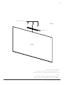
Epson 100in. Da-Lite IDEA Screen for Projection and Dry Erase Guide d'installation
- Taper
- Guide d'installation

INSTRUCTION MANUAL
100" IDEA
™
Screen
for Epson BrightLink Displays (16:9)
© 2020 Legrand AV Inc. 200028 3/20 Da-Lite is a registered trademark of Legrand AV Inc.
All other brand names or marks are used for identiication purposes and are trademarks of their respective
owners. All patents are protected under existing designations. Other patents pending.
FOR YOUR IMAGE | legrandav.com
USA P 866.977.3901 E av[email protected]
CANADA P 877.345.4329 E av[email protected]
EMEA P +31 495 580 840 E av[email protected]
APAC P +852 2145 4099 E av[email protected]
14028

2
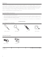
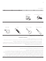
Tools Required For Assembly
Phillips Screwdriver
Level
Rubber Mallet
Measuring Tape
Hardware Provided
(7) #8 x ½" Screws
(1) Wall Bracket
(2) LBrackets
Disclaimer
Legrand AV Inc. and its ailiated companies and subsidiaries (collectively, “Legrand AV”), intend to make this manual accurate and
complete. However, Legrand AV makes no claim that the information contained herein covers all details, conditions or variations, nor
does it provide for every possible contingency in connection with the installation or use of the products described herein. The content
herein is subject to change without notice or obligation of any kind. To the maximum extent permitted by applicable law, Legrand AV
makes no representation or warranty, expressed or implied, regarding the information contained herein. Furthermore, Legrand AV
assumes no responsibility for accuracy, completeness or suiciency of the information contained in this document.
Da-Lite® is a registered trademark of Legrand AV. All rights reserved.
Important Safety Instructions
1. Read and understand all instructions before using.
2. Failure to provide adequate structural strength for this component can result in serious personal injury or damage to equipment! It is the
installer’s responsibility to make sure the structure to which this component is attached can support the weight of all equipment. Reinforce
the structure as required before installing the component.
3. Use this projection screen only for its intended use as described in these instructions. Do not use attachments not recommended by the
manufacturer.
Save These Instructions

3
Preparation
Note: Two people are required to assemble an IDEA Screen. To maintain optimal projected image geometry and screen alignment, a lat
and straight wall free from obstructions and angular distortions should be used.
Choose a clean work area for assembly using padded material or other soft, clean materials. The work area should be larger than the
overall screen size and directly in front of the location where the screen is to be installed.
Cleaning
Everyday Cleaning: The supplied foam eraser can be used to clean marks on the screen surface made by everyday dry erase marker
usage. Do not use the Da-Lite spray cleaner in combination with the foam eraser.
Thorough Cleaning: For periodic full screen cleaning or to clean persistent marks from dry erase markers, use the supplied Da-Lite
spray cleaner and cleaning cloth. Use clean or dry sections of the microiber cloth when erasing the screen. This is important to prevent
smearing on the screen while cleaning. To clean permanent markers and other unintentional marks on the surface, use the supplied
foam eraser or the Da-Lite spray cleaner and cleaning cloth.

4
DRAWING AND PART FILE
MODEL
NAME:
TRAY_EXPLODED(EPSON)_NO_IR
MODEL
LOCATION:
S:\Engineering\Solidworks Files\EPSON IDEA\INSTRUCTIONS\
SHEETS:
1 OF 1
THE INFORMATION AND DESIGNS CONTAINED IN THIS DRAWING ARE CONFIDENTIAL
AND PROPRIETARY PROPERTY OF MILESTONE AV TECHNOLOGIES NEITHER THIS
DESIGN NOR ANY INFORMATION CONTAINED IN THIS DRAWING MAY BE
REPRODUCED OR DISCLOSED TO OTHERS WITHOUT EXPRESS WRITTEN CONSENT
OF MILESTONE AV TECHNOLOGIES.
THIS PRINT SUPERSEDES ANY
PRINT DATED PRIOR TO:
PART NO:
26206
5/30/2014
REVISIONS
REV.
DESCRIPTION
CHNGD BY:
DATE:
APPR'D BY:
TOLERANCES:
DECIMAL:
.XX = ±.010
.XXX = ±.005
FRACTIONAL:
= ±.015
ANGULAR:
= ±1°
1:18
DRAWN BY:
ADW
DATE:
4/16/2014
APP'D BY:
DATE:
X.XXXX
1/19/2011
MATERIAL NO:
MULIT
FINISH:
TYPE OF FINISH
sw
NAME:
EXPLODED VIEW FOR INSTRUCTIONS
SCALE:
DA-LITE SCREEN CO.
WARSAW, INDIANA, USA
PART NO:
26206
Assembly Instructions
1. Carefully unpack the unit and place on top of a clean work area.
The viewing surface must face up.
2. Center the marker tray to the bottom of the frame and attach it
with (3) of the provided #8 x ½" screws. Insert screws through the
tray into the groove (Figure 1).
#8 X ½" Screws
Figure 1
Marker Tray
Front

5
DRAWING AND PART FILE
MODEL
NAME:
MOUNTING EXPLODED(EPSON)_NO_IR
MODEL
LOCATION:
S:\Engineering\Solidworks Files\EPSON IDEA\INSTRUCTIONS\
SHEETS:
1 OF 1
THE INFORMATION AND DESIGNS CONTAINED IN THIS DRAWING ARE CONFIDENTIAL
AND PROPRIETARY PROPERTY OF MILESTONE AV TECHNOLOGIES NEITHER THIS
DESIGN NOR ANY INFORMATION CONTAINED IN THIS DRAWING MAY BE
REPRODUCED OR DISCLOSED TO OTHERS WITHOUT EXPRESS WRITTEN CONSENT
OF MILESTONE AV TECHNOLOGIES.
THIS PRINT SUPERSEDES ANY
PRINT DATED PRIOR TO:
PART NO:
26206
5/30/2014
REVISIONS
REV.
DESCRIPTION
CHNGD BY:
DATE:
APPR'D BY:
TOLERANCES:
DECIMAL:
.XX = ±.010
.XXX = ±.005
FRACTIONAL:
= ±.015
ANGULAR:
= ±1°
1:18
DRAWN BY:
ADW
DATE:
4/16/2014
APP'D BY:
DATE:
X.XXXX
1/19/2011
MATERIAL NO:
MULIT
FINISH:
TYPE OF FINISH
sw
NAME:
EXPLODED VIEW FOR INSTRUCTIONS
SCALE:
DA-LITE SCREEN CO.
WARSAW, INDIANA, USA
PART NO:
26206
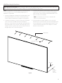
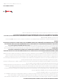
Wall Mounting Instructions
NOTE: Use appropriate mounting hardware for the wall type and
to accommodate for the screen’s hanging weight (Figure 2).
Hardware is not provided.
1. Secure the wall bracket to wall studs at the desired height. Center
the wall bracket with the screen frame. You will need at least 1"
clearance above the drilled holes to hang the screen (Figure 2).
2. To install the (2) L-brackets, you must measure the overall height
of the screen frame and subtract 1⅛" (29 mm). Using that
dimension, measure down from the top edge of the wall brackets
and mark the wall for two screw holes. The outside edge of each
L-bracket must be no greater than 5" (127 mm) away from the left
and right edges of the screen frame (Figure 2).
3. Secure the two L-brackets to the wall at the marked locations. The
longest side of the two L-brackets should be pointing upwards
when secured in order to hide the L-brackets behind the screen
frame once the screen is installed.
NOTE: The L-brackets are necessary to maintain a lat
surface for touch interactivity.
4. This step requires two people. Hang the screen on the wall
brackets. There is a lip on the back of the frame that wedges itself
into the wall brackets once fully installed. Ensure that the screen
clears the L-brackets and that the screen weight is on the wall
brackets, not the L-brackets.
Wall Bracket
LBracket
No More
than 5"
(127 mm)
Figure 2
Determining Screen Placement: When installing the IDEA Screen with BrightLink projectors, you must leave at least 22" (56 cm) of
space between the top of the screen and the ceiling to accommodate the projector wall mount.
Screws (Not Supplied)

6
DRAWING AND PART FILE
MODEL
NAME:
LOWER_ATTACHMENT_EXPLODED(EPSON)_NO_IR
MODEL
LOCATION:
S:\Engineering\Solidworks Files\EPSON IDEA\INSTRUCTIONS\
SHEETS:
1 OF 1
THE INFORMATION AND DESIGNS CONTAINED IN THIS DRAWING ARE CONFIDENTIAL
AND PROPRIETARY PROPERTY OF MILESTONE AV TECHNOLOGIES NEITHER THIS
DESIGN NOR ANY INFORMATION CONTAINED IN THIS DRAWING MAY BE
REPRODUCED OR DISCLOSED TO OTHERS WITHOUT EXPRESS WRITTEN CONSENT
OF MILESTONE AV TECHNOLOGIES.
THIS PRINT SUPERSEDES ANY
PRINT DATED PRIOR TO:
PART NO:
26206
5/30/2014
REVISIONS
REV.
DESCRIPTION
CHNGD BY:
DATE:
APPR'D BY:
TOLERANCES:
DECIMAL:
.XX = ±.010
.XXX = ±.005
FRACTIONAL:
= ±.015
ANGULAR:
= ±1°
1:18
DRAWN BY:
ADW
DATE:
4/16/2014
APP'D BY:
DATE:
X.XXXX
1/19/2011
MATERIAL NO:
MULIT
FINISH:
TYPE OF FINISH
sw
NAME:
EXPLODED VIEW FOR INSTRUCTIONS
SCALE:
DA-LITE SCREEN CO.
WARSAW, INDIANA, USA
PART NO:
26206
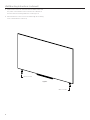
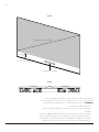
Wall Mounting Instructions (continued)
5. Tap the bottom of the two L-brackets with the rubber mallet until
they make contact with the frame. Secure the two L-brackets to
the frame with the remaining (4) #8 x ½" screws (Figure 3).
6. Attach the bottom of the screen to the wall through the mounting
holes located under the marker tray.
#8 X ½" Screws
Figure 3
#8 X ½" Screws

7
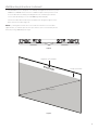
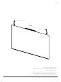
Wall Mounting Instructions (continued)
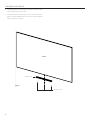
7. The 16:9 IDEA Screen is designed for use with Epson BrightLink Interactive Projectors
(1480 series, 720/730 series). As such, 3" of additional space at the top of the screen
accommodate direct mounting of the BrightLink touch module (Figure 4) to the
screen, while still allowing room for a full 100" diagonal 16:9 display.
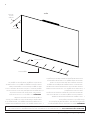
The touch module attaches directly to the IDEA Screen using the magnets on the
back of the touch module (Figure 5).
NOTE: If your BrightLink model does not include an interactive touch module,
approximately 3" of blank space at the top or bottom of the screen will be present
when projecting a 100" diagonal image.
Figure 4
DRAWING AND PART FILE
MODEL
NAME:
LOWER_ATTACHMENT_EXPLODED(EPSON)_NO_IR
MODEL
LOCATION:
S:\Engineering\Solidworks Files\EPSON IDEA\INSTRUCTIONS\
SHEETS:
1 OF 1
PART NO:
26206
REVISIONS
REV.
DESCRIPTION
CHNGD BY:
DATE:
APPR'D BY:
TOLERANCES:
DECIMAL:
.XX = ±.010
.XXX = ±.005
FRACTIONAL:
= ±.015
ANGULAR:
= ±1°
1:18
DRAWN BY:
ADW
DATE:
4/16/2014
APP'D BY:
DATE:
X.XXXX
1/19/2011
MATERIAL NO:
MULIT
FINISH:
TYPE OF FINISH
sw
NAME:
EXPLODED VIEW FOR INSTRUCTIONS
SCALE:
DA-LITE SCREEN CO.
WARSAW, INDIANA, USA
PART NO:
26206
Figure 5
BrightLink Touch Module
Non-projected Area
3"
100" Diagonal

COMMERCIAL BRANDS
Chief | Da-Lite | Middle Atlantic | Projecta | Vaddio
LIMITED FIVEYEAR WARRANTY ON DALITE PRESENTATION PRODUCTS
Legrand AV Inc. warrants certain Da-Lite branded products to the original purchaser only, to be free from defects in materials and
workmanship for a period of ive (5) years from the date of purchase by the original purchaser; provided they are properly operated
according to Da-Lite's instructions and are not damaged due to improper handling or treatment after shipment from the factory.
Limited ive-year warranty applies to the following products:
Wireline Advantage®, Tensioned Advantage Series, Advantage Series, Tensioned DescenderPro, DescenderPro, Tensioned Conference,
Tensioned Professional, Professional, Da-Lift Projector Lifts, Tensioned Contour®, Contour, Tensioned Cosmopolitan® Series,
Cosmopolitan Series, Designer Contour, Slimline, Studio, Arena, Motorized Scenic Roller, Ascender, Parallax®, Parallax Thin, FullVision,
UTB Contour, Cinema Contour, Da-Snap, Perm-Wall, Imager, IDEA™ Screen, IDEA Panoramic, Fast-Fold® Deluxe, Fast-Fold Deluxe Drapery
Kits, Flex Plex, Da-Glas, Da-Plex Rear Projection Mirror System, and Holo Screen.
This warranty does not apply to equipment showing evidence of misuse, abuse or accidental damage, or which has been tampered
with or repaired by a person other than authorized Da-Lite personnel.
Da-Lite’s sole obligation under this warranty shall be to repair or to replace (at Da-Lite’s option) the defective part of the merchandise.
Returns for service should be made to your Da-Lite dealer. If it is necessary for the dealer to return the screen or part to Da-Lite,
transportation expenses to and from Da-Lite are payable by the purchaser and Da-Lite is not responsible for damage in shipment. To
protect yourself against damage or loss in transit, insure the product and prepay all transportation expenses.
TO THE MAXIMUM EXTENT PERMITTED BY APPLICABLE LAW, THIS WARRANTY IS IN LIEU OF ALL OTHER WARRANTIES, EXPRESS
OR IMPLIED, INCLUDING WARRANTIES AS TO FITNESS FOR USE AND MERCHANTABILITY. Any implied warranties of itness for use,
or merchantability, that may be mandated by statute or rule of law are limited to the ive (5) year warranty period. This warranty gives
you speciic legal rights, and you may also have other rights, which vary from state-to-state. TO THE MAXIMUM EXTENT PERMITTED
BY APPLICABLE LAW, NO LIABILITY IS ASSUMED FOR EXPENSES OR DAMAGES RESULTING FROM INTERRUPTION IN OPERATION
OF EQUIPMENT, OR FOR INCIDENTAL, DIRECT, OR CONSEQUENTIAL DAMAGES OF ANY NATURE.
In the event that there is a defect in materials or workmanship of a Da-Lite product, you may contact Customer Care at 3100 North
Detroit Street, Warsaw, IN 46582, (866) 9773901.
IMPORTANT: THIS WARRANTY SHALL NOT BE VALID AND DALITE BRANDED PRODUCTS SHALL NOT BE BOUND BY THIS
WARRANTY IF THE PRODUCT IS NOT OPERATED IN ACCORDANCE WITH THE DALITE WRITTEN INSTRUCTIONS.
Keep your sales receipt to prove the date of purchase and your original ownership.

MARQUES COMMERCIALES
Chef |Da-Lite |Atlantique moyen |Projecta |Vaddio
GARANTIE LIMITÉE DE CINQ ANS SUR LES PRODUITS DE PRÉSENTATION DALITE
Legrand AV Inc. garantit certains produits de la marque Da-Lite à l'acheteur original seulement, contre tout défaut de matériaux et de
fabrication pendant une période de cinq (5) ans à compter de la date d'achat par l'acheteur original; à condition qu'ils soient
correctement utilisés conformément aux instructions de Da-Lite et qu'ils ne soient pas endommagés en raison d'une manipulation ou
d'un traitement incorrect après l'expédition de l'usine.
Une garantie limitée de cinq ans s'applique aux produits suivants :
Wireline Advantage®, Tensioned Advantage Series, Advantage Series, Tensioned DescenderPro, DescenderPro, Tensioned Conference,
Tensioned Professional, Professional, Da-Lift Projector Lifts, Tensioned Contour®, Contour, Tensioned Cosmopolitan® Series,
Cosmopolitan Series, Designer Contour, Slimline, Studio, Arena, Motorized Scenic Roller, Ascender, Parallax®, Parallax Thin, FullVision,
UTB Contour, Cinema Contour, Da-Snap, Perm-Wall, Imager, IDEA™ Screen, IDEA Panoramic, Fast-Fold® Deluxe, Fast-Fold Deluxe Drapery
Kits, Flex Plex, Da-Glas, Da-Plex Rear Projection Mirror System, and Holo Screen.
Cette garantie ne s'applique pas aux équipements présentant des preuves de mauvaise utilisation, d'abus ou de dommages accidentels,
ou qui ont été falsiiés ou réparés par une personne autre que le personnel Da-Lite autorisé.
La seule obligation de Da-Lite en vertu de cette garantie sera de réparer ou de remplacer (au choix de Da-Lite) la partie défectueuse de
la marchandise. Les retours de service doivent être efectués auprès de votre revendeur Da-Lite. S'il est nécessaire que le revendeur
retourne l'écran ou la pièce à Da-Lite, les frais de transport vers et depuis Da-Lite sont à la charge de l'acheteur et Da-Lite n'est pas
responsable des dommages lors de l'expédition. Pour vous protéger contre les dommages ou les pertes de transport, assurez le produit
et prépayez tous les frais de transport.
DANS LA MESURE MAXIMALE PERMISE PAR LA LOI APPLICABLE, CETTE GARANTIE REMPLACE TOUTES LES AUTRES GARANTIES,
EXPRESSES OU IMPLICITES, Y COMPRIS LES GARANTIES CONCERNANT L'APTITUDE À L'UTILISATION ET LA QUALITÉ
MARCHANDE. Toutes les garanties implicites d'aptitude à l'emploi ou de qualité marchande qui peuvent être imposées par la loi ou la
règle de droit sont limitées à la période de garantie de cinq (5) ans. Cette garantie vous donne des droits légaux spéciiques, et vous
pouvez également avoir d'autres droits, qui varient d'un État à l'autre. DANS LA MESURE MAXIMALE PERMISE PAR LA LOI
APPLICABLE, AUCUNE RESPONSABILITÉ N'EST ASSUMÉE POUR LES FRAIS OU DOMMAGES RÉSULTANT D'UNE INTERRUPTION
DANS LE FONCTIONNEMENT DE L'ÉQUIPEMENT, OU POUR DES DOMMAGES ACCESSOIRES, DIRECTS OU CONSÉCUTIFS DE TOUTE
NATURE.
En cas de défaut de matériau ou de fabrication d'un produit Da-Lite, vous pouvez contacter le service client au 3100 North Detroit
Street, Varsovie, IN 46582, (866) 9773901.
IMPORTANT : CETTE GARANTIE NE SERA PAS VALABLE ET LES PRODUITS DE MARQUE DALITE NE SERONT PAS LIÉS PAR CETTE
GARANTIE SI LE PRODUIT N'EST PAS UTILISÉ CONFORMÉMENT AUX INSTRUCTIONS ÉCRITES DE DALITE.
Conservez votre ticket de caisse pour prouver la date d'achat et votre propriété d'origine.

7
Instructions de montage mural (suite)
7. L'écran IDEA 16:9 est conçu pour être utilisé avec les projecteurs interactifs Epson
BrightLink (série 1480, série 720/730). Ainsi, 3 po (76,2 mm) d'espace supplémentaire
en haut de l'écran permettent un montage direct du module tactile BrightLink (igure
4) sur l'écran, tout en laissant de la place pour un aichage 16:9 de 100 po (2,45 m) en
diagonale.
Le module tactile se connecte directement à l'écran IDEA à l'aide des aimants à
l'arrière du module tactile (Figure 5).
REMARQUE : Si votre modèle BrightLink ne comprend pas de module tactile
interactif, environ 3 po (76,2 mm) d'espace vide en haut ou en bas de l'écran sera
présent lors de la projection d'une image en diagonale de 100 po (2,54 m).
Figure 4
DRAWING AND PART FILE
MODEL
NAME:
LOWER_ATTACHMENT_EXPLODED(EPSON)_NO_IR
MODEL
LOCATION:
S:\Engineering\Solidworks Files\EPSON IDEA\INSTRUCTIONS\
SHEETS:
1 OF 1
PART NO:
26206
REVISIONS
REV.
DESCRIPTION
CHNGD BY:
DATE:
APPR'D BY:
TOLERANCES:
DECIMAL:
.XX = ±.010
.XXX = ±.005
FRACTIONAL:
= ±.015
ANGULAR:
= ±1°
1:18
DRAWN BY:
ADW
DATE:
4/16/2014
APP'D BY:
DATE:
X.XXXX
1/19/2011
MATERIAL NO:
MULIT
FINISH:
TYPE OF FINISH
sw
NAME:
EXPLODED VIEW FOR INSTRUCTIONS
SCALE:
DA-LITE SCREEN CO.
WARSAW, INDIANA, USA
PART NO:
26206
Figure 5
Module tactile BrightLink
Zone non projetée
3 po
(76,2 mm)
100 po (2,54 m) en diagonale

6
DRAWING AND PART FILE
MODEL
NAME:
LOWER_ATTACHMENT_EXPLODED(EPSON)_NO_IR
MODEL
LOCATION:
S:\Engineering\Solidworks Files\EPSON IDEA\INSTRUCTIONS\
SHEETS:
1 OF 1
THE INFORMATION AND DESIGNS CONTAINED IN THIS DRAWING ARE CONFIDENTIAL
AND PROPRIETARY PROPERTY OF MILESTONE AV TECHNOLOGIES NEITHER THIS
DESIGN NOR ANY INFORMATION CONTAINED IN THIS DRAWING MAY BE
REPRODUCED OR DISCLOSED TO OTHERS WITHOUT EXPRESS WRITTEN CONSENT
OF MILESTONE AV TECHNOLOGIES.
THIS PRINT SUPERSEDES ANY
PRINT DATED PRIOR TO:
PART NO:
26206
5/30/2014
REVISIONS
REV.
DESCRIPTION
CHNGD BY:
DATE:
APPR'D BY:
TOLERANCES:
DECIMAL:
.XX = ±.010
.XXX = ±.005
FRACTIONAL:
= ±.015
ANGULAR:
= ±1°
1:18
DRAWN BY:
ADW
DATE:
4/16/2014
APP'D BY:
DATE:
X.XXXX
1/19/2011
MATERIAL NO:
MULIT
FINISH:
TYPE OF FINISH
sw
NAME:
EXPLODED VIEW FOR INSTRUCTIONS
SCALE:
DA-LITE SCREEN CO.
WARSAW, INDIANA, USA
PART NO:
26206
Instructions de montage mural (suite)
5. Tapoter le bas des deux supports en L avec le maillet en
caoutchouc jusqu'à ce qu'ils entrent en contact avec le cadre.
Fixer les deux supports en L au châssis avec les (4) vis n° 8 x ½ po
(12,7 mm) (Figure 3) restantes.
6. Fixer le bas de l'écran au mur à travers les trous de montage
situés sous le plateau de marqueur.
Vis n° 8 X ½ po (12,7 mm)
Figure 3
Vis n° 8 X ½po (12,7 mm)

5
DRAWING AND PART FILE
MODEL
NAME:
MOUNTING EXPLODED(EPSON)_NO_IR
MODEL
LOCATION:
S:\Engineering\Solidworks Files\EPSON IDEA\INSTRUCTIONS\
SHEETS:
1 OF 1
THE INFORMATION AND DESIGNS CONTAINED IN THIS DRAWING ARE CONFIDENTIAL
AND PROPRIETARY PROPERTY OF MILESTONE AV TECHNOLOGIES NEITHER THIS
DESIGN NOR ANY INFORMATION CONTAINED IN THIS DRAWING MAY BE
REPRODUCED OR DISCLOSED TO OTHERS WITHOUT EXPRESS WRITTEN CONSENT
OF MILESTONE AV TECHNOLOGIES.
THIS PRINT SUPERSEDES ANY
PRINT DATED PRIOR TO:
PART NO:
26206
5/30/2014
REVISIONS
REV.
DESCRIPTION
CHNGD BY:
DATE:
APPR'D BY:
TOLERANCES:
DECIMAL:
.XX = ±.010
.XXX = ±.005
FRACTIONAL:
= ±.015
ANGULAR:
= ±1°
1:18
DRAWN BY:
ADW
DATE:
4/16/2014
APP'D BY:
DATE:
X.XXXX
1/19/2011
MATERIAL NO:
MULIT
FINISH:
TYPE OF FINISH
sw
NAME:
EXPLODED VIEW FOR INSTRUCTIONS
SCALE:
DA-LITE SCREEN CO.
WARSAW, INDIANA, USA
PART NO:
26206
Instructions de montage mural
REMARQUE : Utiliser le matériel de montage approprié pour le
type de mur et pour tenir compte du poids de suspension de
l'écran (igure 2). Le matériel n'est pas fourni.
1. Fixer le support mural aux poteaux muraux à la hauteur
souhaitée. Centrer le support mural avec le cadre de l'écran. Vous
aurez besoin d'au moins 1 po d'espace au-dessus des trous percés
pour accrocher l'écran (Figure 2).
2. Pour installer les (2) supports en L, vous devez mesurer la hauteur
totale du cadre de l'écran et soustraire 1⅛ po (29 mm). En utilisant
cette dimension, mesurer depuis le bord supérieur des supports
muraux et marquez le mur pour deux trous de vis. Le bord
extérieur de chaque support en L ne doit pas être à plus de 5 po
(127 mm) des bords gauche et droit du cadre de l'écran (Figure 2).
3. Fixer les deux supports en L au mur aux emplacements marqués.
Le côté le plus long des deux supports en L doit être dirigé vers le
haut lorsqu'ils sont ixés ain de cacher les supports en L derrière
le cadre de l'écran une fois que l'écran est installé.
REMARQUE : Les supports en L sont nécessaires pour
maintenir une surface plane pour l'interactivité tactile.
4. Cette étape nécessite deux personnes. Accrocher l'écran sur les
supports muraux. Il y a une lèvre à l'arrière du cadre qui se coince
dans les supports muraux une fois complètement installée.
S'assurer que l'écran dégage les supports en L et que le poids de
l'écran est sur les supports muraux, pas sur les supports en L.
Support mural
Support en L
Pas plus
de 5 po
(127 mm)
Figure 2
Déterminer le placement de l'écran : Lors de l'installation de l'écran IDEA avec des projecteurs BrightLink, vous devez laisser au
moins 22 po (55,88 cm) d'espace entre le haut de l'écran et le plafond pour accueillir le support mural du projecteur.
Vis (non fournies)

4
DRAWING AND PART FILE
MODEL
NAME:
TRAY_EXPLODED(EPSON)_NO_IR
MODEL
LOCATION:
S:\Engineering\Solidworks Files\EPSON IDEA\INSTRUCTIONS\
SHEETS:
1 OF 1
THE INFORMATION AND DESIGNS CONTAINED IN THIS DRAWING ARE CONFIDENTIAL
AND PROPRIETARY PROPERTY OF MILESTONE AV TECHNOLOGIES NEITHER THIS
DESIGN NOR ANY INFORMATION CONTAINED IN THIS DRAWING MAY BE
REPRODUCED OR DISCLOSED TO OTHERS WITHOUT EXPRESS WRITTEN CONSENT
OF MILESTONE AV TECHNOLOGIES.
THIS PRINT SUPERSEDES ANY
PRINT DATED PRIOR TO:
PART NO:
26206
5/30/2014
REVISIONS
REV.
DESCRIPTION
CHNGD BY:
DATE:
APPR'D BY:
TOLERANCES:
DECIMAL:
.XX = ±.010
.XXX = ±.005
FRACTIONAL:
= ±.015
ANGULAR:
= ±1°
1:18
DRAWN BY:
ADW
DATE:
4/16/2014
APP'D BY:
DATE:
X.XXXX
1/19/2011
MATERIAL NO:
MULIT
FINISH:
TYPE OF FINISH
sw
NAME:
EXPLODED VIEW FOR INSTRUCTIONS
SCALE:
DA-LITE SCREEN CO.
WARSAW, INDIANA, USA
PART NO:
26206
Instructions de montage
1. Déballer soigneusement l'appareil et placer-le sur une zone de
travail propre. La surface d'observation doit être tournée vers le
haut.
2. Centrer le porte-marqueur au bas du cadre et ixer-le avec (3) des
vis n° 8 x ½ po (12,7 mm) fournies. Insérer les vis à travers le
plateau dans la rainure (Figure 1).
Vis n° 8 X ½ po (12,7 mm)
Figure 1
Porte-marqueur
Avant

3
Préparation
Remarque : Deux personnes sont nécessaires pour assembler un écran IDEA. Pour maintenir une géométrie d'image projetée et un
alignement d'écran optimaux, un mur plat et droit exempt d'obstructions et de distorsions angulaires doit être utilisé.
Choisir une zone de travail propre pour l'assemblage en utilisant un matériau rembourré ou d'autres matériaux doux et propres. La zone
de travail doit être plus grande que la taille globale de l'écran et directement en face de l'emplacement où l'écran doit être installé.
Nettoyage
Nettoyage quotidien: La gomme en mousse fournie peut être utilisée pour nettoyer les marques sur la surface de l'écran faites par
l'utilisation quotidienne de marqueur efaçable à sec. Ne pas utiliser le nettoyant en spray Da-Lite en combinaison avec la gomme à
efacer.
Nettoyage en profondeur: Pour un nettoyage complet d'écran périodique ou pour nettoyer les marques persistantes des marqueurs
efaçables à sec, utiliser le nettoyant en spray Da-Lite et le chifon de nettoyage fournis. Utiliser des sections propres ou sèches du
chifon en microibre lors de l'efacement de l'écran. Ceci est important pour éviter les taches sur l'écran pendant le nettoyage. Pour
nettoyer les marqueurs permanents et autres marques involontaires sur la surface, utiliser la gomme en mousse fournie ou le nettoyant
en aérosol et le chifon de nettoyage Da-Lite.

2
Outils requis pour l'assemblage
Tournevis cruciforme
Niveau
Maillet en caoutchouc
Mètre ruban
Matériel fourni
(7) Vis n° 8 x ½po (12,7 mm)
(1) Support mural
(2) Supports en L
Avertissement
Legrand AV Inc. et ses sociétés ailiées et iliales (collectivement, « Legrand AV »), ont l'intention de rendre ce manuel précis et complet.
Cependant, Legrand AV ne prétend pas que les informations contenues dans ce document couvrent tous les détails, conditions ou
variations, ni ne prévoient toutes les éventualités possibles en relation avec l'installation ou l'utilisation des produits décrits ici. Le
contenu du présent document est susceptible d'être modiié sans préavis ni obligation d'aucune sorte. Dans la mesure maximale
autorisée par la loi applicable, Legrand AV ne fait aucune représentation ou garantie, expresse ou implicite, concernant les informations
contenues dans le présent document. De plus, Legrand AV n'assume aucune responsabilité pour l'exactitude, l'exhaustivité ou la
suisance des informations contenues dans ce document.
Da-Lite® est une marque déposée de Legrand AV. Tous les droits sont réservés.
Instructions de sécurité importantes
1. Lire et comprendre toutes les instructions avant d'utiliser.
2. Le fait de ne pas fournir une résistance structurelle adéquate à ce composant peut entraîner des blessures graves ou endommager
l'équipement! Il est de la responsabilité de l'installateur de s'assurer que la structure à laquelle ce composant est ixé peut supporter
le poids de tous les équipements. Renforcer la structure au besoin avant d'installer le composant.
3. Utiliser cet écran de projection uniquement pour l'usage auquel il est destiné, comme décrit dans ces instructions. Ne pas utiliser
d'accessoires non recommandés par le fabricant.
Conserver ces instructions

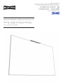
MANUEL D'INSTRUCTION
100 po (2,54 m) IDEA
™
Écran
pour les écrans Epson BrightLink (16:9)
© 2020 Legrand AV Inc. 200028 3/20 Da-Lite est une marque déposée de Legrand AV Inc.
Tous les autres noms de marque ou marques sont utilisés à des ins d'identiication et sont des marques
commerciales de leurs propriétaires respectifs. Tous les brevets sont protégés par des appellations
existantes. Autres brevets en instance.
POUR VOTRE IMAGE | legrandav.com
États-Unis P 866.977.3901 E av.da-lite.support@legrand.com
CANADA P 877.345.4329 E av.da-lite.[email protected]
EMEA P +31 495 580 840 E av.emea.sales@legrand.com
APAC P +852 2145 4099 E av[email protected]
16028
-
 1
1
-
 2
2
-
 3
3
-
 4
4
-
 5
5
-
 6
6
-
 7
7
-
 8
8
-
 9
9
-
 10
10
-
 11
11
-
 12
12
-
 13
13
-
 14
14
-
 15
15
-
 16
16


Epson 100in. Da-Lite IDEA Screen for Projection and Dry Erase Guide d'installation
- Taper
- Guide d'installation
dans d''autres langues
Documents connexes
-
Epson BrightLink 450Wi Guide de démarrage rapide
-
Epson BrightLink 455Wi Guide de démarrage rapide
-
Epson BrightLink Pro 1410Wi Guide d'installation
-
Epson PowerLite 460 Guide d'installation
-
Epson PowerLite 580 for SMART Guide d'installation
-
-
Epson BrightLink Pro 1420Wi Guide d'installation
-
Epson PowerLite 685W for SMART Guide d'installation
-
Epson PowerLite 435W Guide d'installation
-
Epson BrightLink Pro 1470Ui Guide d'installation