Bradley SN2013 Guide d'installation
- Catégorie
- Articles sanitaires
- Taper
- Guide d'installation
Ce manuel convient également à

Installation
P.O. Box 309
Menomonee Falls, WI 53052 USA
800 BRADLEY (800 272 3539)
+1 262 251 6000
bradleycorp.com
215-923 Rev. M; ECN 17-00-002
© 2017 Bradley
Page 1 of 34 8/21/2017
SN2033 - Infrared
SN2013 - Infrared
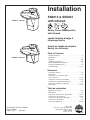
SN2013 & SN2033
with Infrared
Table of Contents
Supplies Required ...............................2
Dimensions ....................................3
Rough-In ....................................4-5
Installation Instructions .........................6-8
Optional Equipment Installation.....................9
Cleaning and Maintenance .......................10
Troubleshooting .............................11-12
Sommaire
Fournitures requises ............................13
Dimensions ...................................14
Informations sur la mise en place
des tuyauteries .............................15-16
Instructions relatives à l’installation..............17-19
Installation de l’équipement optionnel ...............20
Instructions relatives au nettoyage .................21
Dépannage ................................22-23
Tabla de contenidos
Materiales necesarios ...........................24
Dimensiones ..................................25
Información sobre tuberías empotradas ..........26-27
Instrucciones de instalación ...................28-30
Instalaciones de equipos opcionales................31
Instrucciones de limpieza ........................32
Solución de problemas .......................33-34
U
P
C
R
C
Sentry Corner Washfountain
with Infrared
Lavabo fontaine d’angle à
infrarouge Sentry
Fuente de lavado de esquina
Sentry con infrarrojo

SN2013, SN2033 - Infrared Installation
2 8/21/2017 Bradley • 215-923 Rev. M; ECN 17-00-002
Supplies required for installation
• 3/8" diameter bolts and floor/wall anchors to anchor washfountain pedestal to floor and wall
• 1/2" nominal copper tubing for hot and cold water supply lines
• Standard P-trap (trap included with “B” or “H” drain type and some optional equipment)
• 1-1/2" drain lines and fittings
• Pipe sealant
• 110 VAC power source and conduit box for 120/12VDC plug in adapter
• 18-gauge two-conductor lamp cord with female connectors
Supplies recommended for installation
• 1-1/2" vent or tie pipe on types vented through washfountain column
• Caulk (may be applied between backsplash and wall to avoid debris accumulation)
• Electrical cut-off switch to the unit. This feature prevents accidental water delivery during regular
maintenance and service.
WARNING
Water supply requires a flowing pressure of at least 20 psi, but no greater than 80 psi.
Make sure that all water supply lines have been flushed and then completely turned off before beginning
installation. Debris in supply lines can cause valves to malfunction.
Hardware supplied by installer must be appropriate for wall construction. Wall anchors used must have a
minimum pull-out rating of 1,000 lbs.
The Accuzone infrared activation must be connected with a 12V DC plug-in adapter. Connections to 110 VAC
can cause personal injury and will result in damage to the electronics.
IMPORTANT
Read this entire installation manual to ensure proper installation. When finished with the installation, file
this manual with the owner or maintenance department. Compliance and conformity to local codes and
ordinances is the responsibility of the installer.
Separate parts from packaging and make sure all parts are accounted for before discarding any packaging
material. If any parts are missing, do not begin installation until you obtain the missing parts.
Product warranties may be found under "Products" on our website at www.bradleycorp.com.

Installation SN2013, SN2033 - Infrared
Bradley • 215-923 Rev. M; ECN 17-00-002 8/21/2017 3
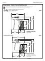
Dimensions - Sentry Corner Washfountain
(mm)
Standard and Juvenile height models with Infrared
control are ADA/TAS compliant.
Floor-Mounted with Infrared
43-3/4"
(1111)
25-1/16"
(637)
13-5/16"
(338)
18-3/4"
(476)
29-9/16"*
(751)
33-7/16"*
(849)
45-5/8"*
*(1159)
9"*
(229)
41-7/8"*
(1064)
Wall-Mounted with Infrared
43-3/4"
(1111)
25-1/16"
(637)
13-5/16"
(338)
18-3/4"
(476)
29-9/16"*
(751)
33-7/16"*
(849)
45-5/8"*
(1159)
9"*
(229)
41-7/8"*
(1064)
* Subtract 4" (102) from
this dimension for juvenile
height model.
* Subtract 4" (102) from
this dimension for juvenile
height model.
(mm)
Sentry models available with various mounting heights. Before beginning rough-ins,
verify if the unit is a Standard or Juvenile model and rough-in accordingly.

SN2013, SN2033 - Infrared Installation
4 8/21/2017 Bradley • 215-923 Rev. M; ECN 17-00-002
30-1/8" (765)
15-5/16"
(389)
6-1/8"
(156)
6"
(152)
34-5/16"*
(872)
33-9/16"*
(852)
29-3/4"*
(756)
23"*
(584)
16-3/4" (425) STD
14-3/4" (375) JUV
3-3/4" (95)
11-1/2"
(292) STD
12"
(305) JUV
13-7/16"
(341) STD
13-11/16"
(348) JUV
(mm)
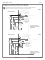
Rough-In Locations for Wall Anchor Bracing
Dimensions are to determine reinforcement locations. Use fixture as a template for precise
location of 3/8" Anchors. Dimensions from corner are the same for both walls.
Floor-Mounted Units
Wall-Mounted Units
4" (102 ) x 4" (102)
110 volt electrical
box (recommended
location: refer to
local codes before
roughing in.)
* Subtract 4" (102) from
this dimension for juvenile
height model.
30-1/8" (765)
6-1/8"
(156)
15-5/16" (389)
34-5/16"*
(872)
33-9/16"*
(852)
29-3/4"*
(756)
23-1/4"*
(591)
17-11/16"*
(449)
13-9/16"
(344)
14-3/8"
(365)
4" (102 ) x 4" (102)
110 volt electrical
box (recommended
location: refer to
local codes before
roughing in.)
6"
(152)
23"*
(584)
* Subtract 4" (102) from
this dimension for juvenile
height model.
(mm)

Installation SN2013, SN2033 - Infrared
Bradley • 215-923 Rev. M; ECN 17-00-002 8/21/2017 5
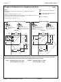
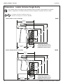
Rough-In Dimensions for Supplies and Drain
Notes
Maximum flow rate required to washfountain is 1.5 GPM. Size supply lines
accordingly.
Supplies from Below: Stub up 2-1/2" (64).
Supplies from Above: Supplies must be located on centers of dimensions shown to
pass through washfountain shroud and sprayhead.
Drain through floor: Stub up 3" (76).
1/2" Supply: Nominal Copper Tube
1/2" Supply Through Wall (Optional):
Nominal Copper Tube
1-1/2" NPT Drain
Key
(mm)
Type B
Centrally rising vent -
passes through center of
unit (P-Trap furnished).
Type O
Off-line vent
(P-Trap supplied
by Installer.)
Type A
Off-line vent
(P-Trap supplied by
Installer.)
Type H
Centrally rising vent -
passes through center of
unit (P-Trap furnished).
Supplies from AboveSupplies from Below or Through Wall
Top View Top View
When running supplies and drain through wall, use same horizontal measurements as shown in Top View.
Position openings above the finished floor, at the following dimensions (to center):
Drain: Standard Height: 19-1/4" (305)
Juvenile Height: 15-1/4" (387)
Supplies: Standard Height: 12" (305)
Juvenile Height: 8" (203)
11-3/4"
(298)
11-3/4"
(298)
18-7/16"
(468)
18-7/16"
(468)
10-5/16"
(262)
10-5/16"
(262)
11-1/2"
(292)
11-1/2"
(292)
12-1/16"
(306)
12-1/16"
(306)
2-9/16"
(65)
6-3/4"
(298)
6-3/4"
(298)
7-15/16"
(202)
11-3/4"
(298)
11-3/4"
(298)
Optional Wall
DRAIN
Optional Wall
DRAIN
H
H
C
C

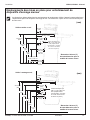
SN2013, SN2033 - Infrared Installation
6 8/21/2017 Bradley • 215-923 Rev. M; ECN 17-00-002
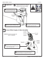
A
Remove Access panel and with
the help of another person, place
unit in position against both walls.
1
Install Unit
Rough-in of plumbing lines, wall braces
and electrical box must be completed
before unit can be properly installed.
C
Install suitable wall anchors (supplied
by installer) for 3/8" bolts at the marked
locations. Secure unit to wall.
Water Supply
Gang Valve
Assembly
B
Ensure unit is level, shimming floor unit if
necessary. Mark the wall anchor locations.
2
Connect Water Supply to Valve Assembly
A
Connect stops to hot and cold water supply.
Connect one end of each supply hose to a
stop and the other end to the hot and cold
inlets of the Navigator TMV.
B
OPTIONAL TEMPERED LINE CONNECTION: Connect one
end of the supply hose to the stop and the other end to the
tempered line adapter in the gang valve assembly.
WARNING! Do not turn on water until
Step 4 is completed!
Red Tube
(to Aerator)
Green Tube
(to Aerator)
Black Tube
(to Aerator)
Hot Supply Inlet
Cold Supply Inlet
Navigator TMV
(S01-526)
Braided
Hose
OPTIONAL
Tempered
Line Adapter
Assembly
(S39-804)
Stop Valve
Water Supply
Gang Valve
Assembly

Installation SN2013, SN2033 - Infrared
Bradley • 215-923 Rev. M; ECN 17-00-002 8/21/2017 7
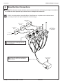
STOP!!! If installing optional Shroud/Slip Ring or Towel Dispensers, complete those installations before
proceeding to Step 4 (see Optional Equipment Installation page).
WARNING! The Accuzone Infrared activation must be connected with a 12V DC plug in adaptor. Connections
to 110 VAC can cause personal injury and will result in damage to the electronics.
3
Make Electrical Connections
IR Sensor
(269-1184-DC)
Left Sensor
(Black)
Center Sensor
(Green)
Right Sensor
(Red)
Plug-In Adapter
(261-147A)
Valve Set
(TMA: S45-3489
TL: S45-3488)
Snap each sensor circuit plug into the
associated solenoid circuit plug located on
the valve bracket.
A
Snap the wall adapter barrel plug into the
barrel plug located on the valve bracket
wire harness.
B

SN2013, SN2033 - Infrared Installation
8 8/21/2017 Bradley • 215-923 Rev. M; ECN 17-00-002
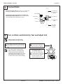
4
Connect Drain
Off-Line Vent (Type A or O): Connect 1-1/2" P-Trap and
drain piping (supplied by installer) to the drain spud.
Centrally Rising Vent (Type B or H) or models with
optional paper towel dispensers: Connect the vented
P-Trap (provided) and drain piping as shown.
Strainer
Tailpiece
Drain Spud
P-Trap
1-1/2" NPT Vent
Pipe (supplied by
installer)
1-1/2" NPT Tee
1-1/2" NPT Close
Nipple
1-1/2" Drain
(supplied by
installer)
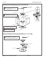
5
Turn on Water and Electricity, Test and Adjust Unit
H
C
B
Loosen the cap screw about
¼" (4–6 turns) and lift up
the cover (do not remove).
C
Using the cover, turn
the cartridge gently until
desired water temperature
is reached. Do not turn past
stops as this may damage
the unit. Push the cover
down and tighten the screw.
This valve is NOT factory preset.
Upon installation, the temperature
of this valve must be checked and
adjusted to ensure delivery of a safe
water temperature. Water in excess
of 110°F (43°C) may cause scalding.
A
Turn on power to transformer. Turn on
water supply and check for leaks. Activate
each infrared sensor to purge air from the
lines.
Check to make sure stop valves
are open before turning on water.

Installation SN2013, SN2033 - Infrared
Bradley • 215-923 Rev. M; ECN 17-00-002 8/21/2017 9
Optional Towel Dispensers and 4-Inch Shroud
Optional Dispenser Mounting Brackets for 1-1/2" Pipe
Vent Pipe (shown for
illustrative purposes)
Mounting Bracket
Shroud
Soap Filler Cap
A
Mount Brackets for a 1-1/2" pipe in a
similar manner to above. Secure brackets in
position using tie-bar supports as shown.
C
Using supplied screws, secure base
of shroud to the sprayhead cover.
D
Connect base of vent pipe to
drain as described in Step 3.
B
Attach Dispensers, using them as a
guide for positioning mounting brackets.
A
Attach Slip Ring to ceiling. Use (5)
1/4" screws (provided by installer), in
a 6" diameter circle.
Spacer Sleeve
Tie Bar
Pipe Cap
Mounting Bracket
Soap Filler Cap

SN2013, SN2033 - Infrared Installation
10 8/21/2017 Bradley • 215-923 Rev. M; ECN 17-00-002
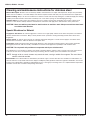
Cleaning and maintenance instructions for stainless steel
Material Description: Stainless steel is extremely durable, and maintenance is simple and inexpensive. Proper care, particularly
under corrosive conditions, is essential. Always start with the simplest solution and work your way toward the more complicated.
Routine cleaning: Daily or as often as needed use a solution of warm water and soap, detergent, or ammonia. Apply the cleaning
solution per the manufacturer’s instructions and always use a soft cloth or sponge to avoid damaging the finish.
Stubborn Stains: To remove stains from stainless steel use a stainless steel cleaner and polish such as Ball
®
stainless steel
cleaner or a soft abrasive. Always follow the manufacturer’s instructions and apply in the same direction as the polish lines.
CAUTION! Never use ordinary steel wool or steel brushes on stainless steel. Always use stainless steel wool
or stainless steel brushes.
Special Situations for Material
Fingerprints and Smears: To remove fingerprints or smears use a high quality stainless steel cleaner and polish in accordance
with the manufacturer’s instructions. Many of these products leave a protective coating that helps prevent future smears and
fingerprints.
Grease and Oil : To remove grease and oil use a quality commercial detergent or caustic cleaner. Apply in accordance to the
manufacturer’s instructions and in the direction of the polish lines.
Precautions: Avoid prolonged contact with chlorides (bleaches, salts), bromides (sanitizing agents), thiocyanates (pesticides,
photography chemicals, and some foods), and iodides on stainless steel equipment, especially if acid conditions exist.
CAUTION! Do not permit salty solutions to evaporate and dry on stainless steel.
The appearance of rust streaks on stainless steel leads to the belief that the stainless steel is rusting. Look for the actual source
of the rust in some iron or steel particles which may be touching, but not actually a part of the stainless steel structure.
NOTE: Strongly acidic or caustic cleaners may attack the steel, causing a reddish film to appear. The use of these
cleaners should be avoided.
Brand Names: Use of brand names is intended only to indicate a type of cleaner. This does not constitute an endorsement, nor
does the omission of any brand name cleaner imply its inadequacy. Many products named are regional in distribution, and can be
found in local supermarkets, department and hardware stores, or through your cleaning service. It is emphasized that all products
should be used in strict accordance with package instructions.

Installation SN2013, SN2033 - Infrared
Bradley • 215-923 Rev. M; ECN 17-00-002 8/21/2017 11
Problem Cause Solution
An individual
operating
station fails
to shut off
and drips.
Internal
cartridge
failure.
Replace cartridge S27-352.
An individual
operating
station fails
to turn on.
A failed
cartridge for
the valve or
loose electrical
connection to
the terminal.
Test the station to determine the cause.
1. Disconnect the wires from the cartridge of an adjacent valve. Disconnect the wires from the
problem valve and reconnect to the adjacent valve.
2. Turn on electrical and water supplies to the unit. Pass your hand in front of the sensor of
the problem station, and the adjacent station should turn on.
If the adjacent station turns on and cycles normally, replace the cartridge on the problem valve.
If the adjacent valve fails to turn on, inspect the wires from the sensor cable and do the following:
• make sure there are no breaks and that the fully insulated disconnect terminals are
firmly crimped in place;
• turn off the electrical and water supplies;
• reconnect to the adjacent valve and turn on the water supplies to the unit;
• pass your hand in front of the sensor. If the station still fails to turn on, replace the
sensor.
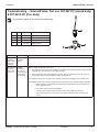
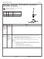
Troubleshooting – Solenoid Valve: Part nos. S07-067-DC (closed body)
& S07-067A-DC (thru body)
Item Qty. Part No. Description
1 1 118-334 Valve Body, ¼" Closed
1 1 118-334A Valve Body, ¼" Thru
2 1 S27-352 Cartridge
3 1 125-165 O-Ring, #2-013
Turn off water supplies to the unit before troubleshooting.
2
1
3

SN2013, SN2033 - Infrared Installation
12 8/21/2017 Bradley • 215-923 Rev. M; ECN 17-00-002
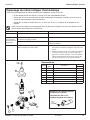
Tempered Line Adapter Option
Part no. S39-804
(replaces S01-526 if tempered
line is used)
Strainer
(173-028)
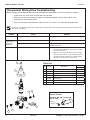
Problem Cause Solution
External leaks. Damaged cartridge or O-rings. Replace cartridge with part number 269-1927
Improper water
temperature or
temperature
fluctuation.
Hot water supply is not 10° above desired set point. Increase hot water supply temperature
Valve temperature is not properly set. Adjust the temperature as previously shown in this
installation manual.
Limited water flow. Dirt and debris have built up in the valve or strainer. 1. Check to make sure both hot and cold supplies are
connected to the Navigator mixing valve and that
they have water flow.
2. Remove cover and U-clip. Remove the cartridge
and clean the strainer. It is not required to grease
cartridge, however if desired, use silicone grease
only. Do not use grease on check valves.
Parts List
Item Part No. Description
Quantity
S59-4000
1 160-463 Cap Screw 1
2 107-582 Cover 1
3 269-1927 Thermostatic Cartridge 1
4 198-014 Check Valve* 2
5 132-051 Retaining Ring* 2
6 118-319 Valve Body 1
7 146-079 U-Clip 1
* Included with Prepack S65-326
1
2
3
4
5
4
5
7
6
Thermostatic Mixing Valve Troubleshooting
Before attempting to troubleshoot the valve or disassemble the components, check for the following conditions:
• If stop valves are used, make sure that they are fully open.
• Make sure that the hot and cold inlet pipes are connected properly, and that there are no cross-
connections or leaking stop valves.
• Check the hot water heater output to make sure that it is at least 10° F above the set temperature.
Be sure to close the appropriate shut-off valves prior to disassembly of the valve and reopen the valves after inspection
and repair is complete.

Installation SN2013, SN2033 - Infrared
Bradley • 215-923 Rev. M; ECN 17-00-002 8/21/2017 13
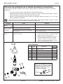
Fournitures requises pour l’installation
• Boulons de 3/8 po de diamètre et dispositifs d’ancrage muraux/de sol pour ancrer le socle du lavabo
fontaine au mur et au sol
• Tube de cuivre de 1/2" nominal pour la tuyauterie d’alimentation d’eau chaude/froide ou tempérée
• Siphon en P standard (siphon fourni avec type de drain « B » ou « H » et certains équipements
optionnels)
• Conduites de drain de 1-1/2 po et raccords
• Produit d’étanchéité pour tuyaux
• Source d’alimentation 110 VCA et boîte de dérivation pour adaptateur enfichable de 120/12 VCC
• Cordon de lampe bifilaire de calibre 18 avec connecteurs femelles
Fournitures requises pour l’installation
• Tuyau d’aération ou canalisation de liaison de 1-1/2 po sur colonne de lavabo fontaine de type à aération
• Mastic (peut s’appliquer entre le dosseret et sol pour éviter toute accumulation de débris)
• Coupe-circuit électrique sur l’unité. Cette fonction empêche toute distribution d’eau accidentelle durant
l’entretien ou les réparations standard.
AVERTISSEMENT
L’alimentation en eau nécessite une pression d’écoulement d’au moins 20 psi, mais ne dépassant pas 80 psi.
Veiller à bien vidanger et fermer toutes les conduites d’eau avant de commencer l’installation. Tout débris
dans les conduites d’alimentation risque de provoquer un mauvais fonctionnement des soupapes.
La visserie fournie par l’installateur doit être adaptée à la nature du mur. Les ancrages muraux utilisés
doivent avoir une résistance nominale à l’arrachement d’au moins 1 000 lb (4,45 kN).
L’activation infrarouge Accuzone doit être raccordée à un adaptateur enfichable de 12 VCC. Le raccordement
à une tension de 110 VCA peut provoquer des blessures corporelles et endommagerait l’électronique.
IMPORTANT
Lire ce manuel d’installation dans son intégralité pour garantir une installation appropriée. Une fois celle-ci
terminée, classer ce manuel auprès du service à la clientèle ou d’entretien. L’installateur est responsable de
respecter la conformité aux codes et ordonnances locaux.
Séparer les pièces de l’emballage et veiller à bien avoir toutes les pièces avant de jeter le matériau
d’emballage. Le cas échéant, ne pas commencer l’installation avant d’avoir obtenu les pièces manquantes.
Les garanties du produit se trouvent sous la rubrique « Products » (Produits) sur notre site Web à
bradleycorp.com

SN2013, SN2033 - Infrared Installation
14 8/21/2017 Bradley • 215-923 Rev. M; ECN 17-00-002
Dimensions - Lavabo fontaine d’angle Sentry
Les modèles de hauteur standard et enfant avec
commande à infrarouge sont conformes ADA/TAS.
(mm)
Unité montées au sol à infrarouge
43-3/4 po
(1111)
25-1/16 po
(637)
13-5/16 po
(338)
18-3/4 po
(476)
29-9/16 po*
(751)
33-7/16 po*
(849)
45-5/8 po*
*(1159)
9 po*
(229)
41-7/8 po*
(1064)
Unité à montage mural à infrarouge
43-3/4 po
(1111)
25-1/16 po
(637)
13-5/16 po
(338)
18-3/4 po
(476)
29-9/16 po*
(751)
33-7/16 po*
(849)
45-5/8 po*
(1159)
9 po*
(229)
41-7/8 po*
(1064)
* Retrancher 102 mm (4")
de cette dimension pour le
modèle de hauteur enfant.
* Retrancher 102 mm (4")
de cette dimension pour le
modèle de hauteur enfant.
(mm)
Les modèles Sentry sont proposés dans différentes hauteurs de pose. Avant de poser la tuyauterie,
vérifier si l’appareil est un modèle standard ou enfant et disposer la tuyauterie comme il se doit.

Installation SN2013, SN2033 - Infrared
Bradley • 215-923 Rev. M; ECN 17-00-002 8/21/2017 15
Emplacements des mises en place pour entretoisement de
dispositifs d’ancrage muraux
Les dimensions doivent déterminer les emplacements de renforcement. Utiliser l’appareil comme gabarit pour
l’emplacement précis des dispositifs d’ancrage de 3/8". Les dimensions à partir du coin sont les mêmes pour
les deux murs.
30-1/8 po (765)
15-5/16 po
(389)
6-1/8 po
(158)
6 po
(152)
34-5/16 po*
(872)
33-9/16 po*
(852)
29-3/4 po*
(756)
23 po*
(584)
3-3/4 po (95)
(mm)
Unités montées au sol
Unités à montage mural
Coffret électrique 4 po
(102 ) x 4 po (102) 110
volts (emplacement
recommandé : consulter
les codes locaux avant
les mises en place.)
* Retrancher 102 mm (4")
de cette dimension pour le
modèle de hauteur enfant.
30-1/8 po (765)
6-1/8 po
(158)
15-5/16 po
(389)
34-5/16 po*
(872)
33-9/16 po*
(852)
29-3/4 po*
(756)
23-1/4 po*
(591)
17-11/16 po*
(449)
13-9/16 po
(344)
14-3/8
po (365)
Coffret électrique 4 po
(102 ) x 4 po (102) 110
volts (emplacement
recommandé : consulter
les codes locaux avant
les mises en place.)
6 po
(152)
23 po*
(584)
* Retrancher 102 mm (4")
de cette dimension pour le
modèle de hauteur enfant.
(mm)
16-3/4 po (425) STD
14-3/4 po (375) JUV
11-1/2 po
(292) STD
12 po
(305) JUV
13-7/16 po
(341) STD
13-11/16 po
(348) JUV

SN2013, SN2033 - Infrared Installation
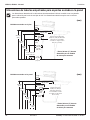
16 8/21/2017 Bradley • 215-923 Rev. M; ECN 17-00-002
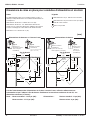
Type B
Aération montante
centralement
- passe au centre de
l’unité (siphon en P fourni).
Type O
Aération hors
canalisation
(siphon en
P fourni par
l’installateur)
Type A
Aération hors
canalisation (siphon
en P fourni par
l’installateur)
Type H
Aération montante
centralement
- passe au centre de l’unité
(siphon en P fourni).
Alimentations du dessusAlimentations du dessous ou à travers le mur
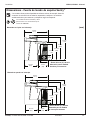
Dimensions de mise en place pour conduites d’alimentation et de drain
Notes
Le débit maximum requis vers le lavabo fontaine est de 1,5
GPM (5,7 LPM). Dimensionner les conduites d’alimentation en
conséquence.
Alimentations du dessous : tubulure de 2-1/2" (64).
Alimentations du dessus : Les alimentations doivent être
situées sur les centres des dimensions indiquées pour passer
à travers l’enveloppe et le bec diffuseur du lavabo fontaine.
Drain dans le sol : tubulure de 3" (76).
Vue de dessus Vue de dessus
Légende
Lors de l’acheminement des alimentations et du drain à travers le mur, utilise les mêmes mesures
horizontales tel que l’indique la Vue du dessus. Positionner les ouvertures au-dessus du sol fini, aux
dimensions suivantes (au centre) :
Drain : Hauteur standard : 19-1/4 po (305) Alimentations : Hauteur standard : 12 po (305)
Hauteur enfant : 15-1/4 po (387) Hauteur enfant : 8 po (203)
(mm)
11-3/4 po
(298)
11-3/4 po
(298)
18-7/16 po
(468)
18-7/16 po
(468)
10-5/16 po
(262)
10-5/16 po
(262)
11-1/2 po
(292)
11-1/2 po
(292)
12-1/16 po
(306)
12-1/16 po
(306)
2-9/16 po
(65)
6-3/4 po
(298)
6-3/4 po
(298)
7-15/16 po
(202)
11-3/4 po
(298)
11-3/4 po
(298)
DRAIN mural
en option
DRAIN
mural en
option
H
H
C
C
Alimentation de 1/2 po : Tube de cuivre nominal
Alimentation de 1/2 po à travers le mur (en option) :
Tube de cuivre nominal
Drain 1-1/2 po NPT

Installation SN2013, SN2033 - Infrared
Bradley • 215-923 Rev. M; ECN 17-00-002 8/21/2017 17
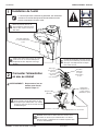
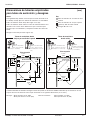
A
Retirer le panneau d’accès et,
avec l’aide d’une autre personne,
mettre l’unité en place contre les
deux murs.
Installation de l’unité
La mise en place des conduites de plomberie, des entretoises
murales et du coffret électrique doit être terminée avant de
pouvoir correctement installer l’unité.
C
Installer des dispositifs d’ancrage muraux
(fournis par l’installateur) pour les boulons
de 3/8 po aux emplacements marqués.
Fixer l’unité au mur.
Ensemble d’appareils
accouplés d’alimentation
en eau
B
Vérifier que l’unité est de niveau, en calant
l’unité au sol le cas échéant. Marquer les
emplacements des dispositifs d’ancrage
muraux.
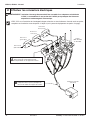
Connecter l’alimentation
en eau au robinet
A
Raccorder les robinets d’arrêt aux arrivées
d’eau chaude et froide. Raccorder un côté
de chaque tuyau d’alimentation à un robinet
d’arrêt et l’autre aux entrées chaude et froide
du TMV Navigator.
B
RACCORDEMENT À UNE CONDUITE TEMPÉRÉE EN
OPTION : Raccorder un robinet d’arrêt à l’arrivée d’eau.
Raccorder un côté du tuyau d’alimentation à un robinet
d’arrêt et l’autre à l’adaptateur de conduite tempérée dans
la vanne de distribution.
AVERTISSEMENT ! Ne pas mettre l’eau en
marche avant d’avoir
terminé l’étape 4 !
1
2
Tube rouge
(vers aérateur)
Tube vert
(vers aérateur)
Tube noir
(vers aérateur)
Arrivée d’alimentation en eau chaude
Arrivée d’alimentation en eau froide
Navigator TMV
(S01-526)
Tuyau à
armature
Ensemble
d’adaptateur de
conduite trempée
(S39-804) en option
Robinetterie arrêt
Ensemble
d’appareils
accouplés
d’alimentation
en eau

SN2013, SN2033 - Infrared Installation
18 8/21/2017 Bradley • 215-923 Rev. M; ECN 17-00-002
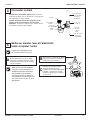
STOP !!! En cas d’installation de l’enveloppe/la bague collectrice ou des distributeurs d’essuie-mains en option,
compléter ces installations avant de passer à l’étape 4 (voir la pose des équipements en option à la page).
AVERTISSEMENT L’activation infrarouge Accuzone doit être raccordée à un adaptateur enfichable de
12 VCC. Le raccordement à une tension de 110 VCA peut provoquer des blessures
corporelles et endommagerait l’électronique.
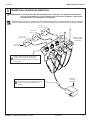
3
Effectuer les connexions électriques
Détecteur IR
(269-1184-DC)
Détecteur à
gauche (Noir)
Détecteur à
centre (Vert)
Détecteur à
droite (Rouge)
Adaptateur enfichable
(261-147A)
Robinet
(TMA: S45-3489
TL: S45-3488)
Brancher chaque fiche de circuit de détecteur
dans la prise de circuit d’électrovanne
correspondante sur le support de vannes.
A
Brancher la fiche cylindrique de
l’adaptateur dans la prise cylindrique du
faisceau de câbles du support de vannes.
B

Installation SN2013, SN2033 - Infrared
Bradley • 215-923 Rev. M; ECN 17-00-002 8/21/2017 19
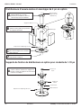
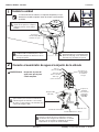
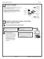
Connecter le drain
Aération hors canalisation (Type A ou O) : Connecter
la tubulure de siphon en P et de drain de 1-1/2 po (fournie
par l’installateur) à l’ergot de drain.
Aération montante centralement (Type B ou H) ou
modèles munis de distributeurs d’essuie-mains
optionnels : Connecter le siphon en P à aération (fourni)
et la tubulure de drain comme indiqué :
Crépine
Pièce de
raccordement
Raccordement
du drain
Siphon
en P
Tuyau d’aération
de 1-1/2 po NPT
(fourni par
l’installateur)
Té de 1-1/2
po NPT
Raccord
étroit de
1-1/2 po
NPT
Drain de 1-1/2 po
(fourni par
l’installateur)
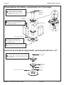
Mettre en marche l’eau et l’électricité ;
tester et ajuster l’unité
4
5
H
C
B
Desserrer la vis à tête de 1/4" (6mm)
environ (4 à 6 tours) et soulever le
capuchon (ne pas l’enlever).
C
À l’aide du capuchon, tourner
lentement la cartouche jusqu’à
obtenir la température d’eau
souhaitée. Pour ne pas endommager
l’appareil, ne pas tourner au-delà
des butées. Renfoncer le capuchon
et serrer la vis.
Cette vanne n’est PAS préréglée
à l’usine. Lors de l’installation, la
température de cette vanne doit
être contrôlée et ajustée pour
s’assurer que l’eau est fournie à
une température sans danger. Une
eau à plus de 43 °C (110 °F) peut
ébouillanter.
A
Mettre le transformateur sous tension.
Ouvrir l’alimentation en eau et vérifier
la présence éventuelle de fuites. Activer
chaque détecteur infrarouge pour purger
l’air des conduites.
Vérifier que la robinetterie arrêt
est ouverte avant d’ouvrir l’eau.

SN2013, SN2033 - Infrared Installation
20 8/21/2017 Bradley • 215-923 Rev. M; ECN 17-00-002
Distributeurs d’essuie-mains et enveloppe de 4 po en option
Supports de fixation de distributeurs en option pour conduite de 1-1/2 po
Tuyau d’aération
(indiqué à des fins
d’illustrations)
Support de fixation
Enveloppe
Capuchon de remplissage de savon
A
Fixer les supports pour un tuyau de 1-1/2 po
comme ci-dessus. Sécuriser les supports en
position à l’aide des supports de fer de liaison
comme il l’est indiqué.
C
À l’aide des vis fournies, sécuriser la
base de l’enveloppe sur le couvercle
du bec diffuseur.
B
Attacher les distributeurs en les
utilisant comme guide pour positionner
les supports de fixation.
A
Attacher la bague collectrice au
plafond. Utiliser (5) vis 1/4 po
(fournies par l’installateur) dans un
cercle de 6 po (152) de diamètre.
Douille-entretoise
Fer de liaison
Bouchon de
tuyau
Support de
fixation
D
Connecter la base du tuyau d’aération
tel que décrit à l’étape 3.
Capuchon de remplissage de savon
La page est en cours de chargement...
La page est en cours de chargement...
La page est en cours de chargement...
La page est en cours de chargement...
La page est en cours de chargement...
La page est en cours de chargement...
La page est en cours de chargement...
La page est en cours de chargement...
La page est en cours de chargement...
La page est en cours de chargement...
La page est en cours de chargement...
La page est en cours de chargement...
La page est en cours de chargement...
La page est en cours de chargement...
-
 1
1
-
 2
2
-
 3
3
-
 4
4
-
 5
5
-
 6
6
-
 7
7
-
 8
8
-
 9
9
-
 10
10
-
 11
11
-
 12
12
-
 13
13
-
 14
14
-
 15
15
-
 16
16
-
 17
17
-
 18
18
-
 19
19
-
 20
20
-
 21
21
-
 22
22
-
 23
23
-
 24
24
-
 25
25
-
 26
26
-
 27
27
-
 28
28
-
 29
29
-
 30
30
-
 31
31
-
 32
32
-
 33
33
-
 34
34


Bradley SN2013 Guide d'installation
- Catégorie
- Articles sanitaires
- Taper
- Guide d'installation
- Ce manuel convient également à
dans d''autres langues
- English: Bradley SN2013 Installation guide
- español: Bradley SN2013 Guía de instalación
Documents connexes
-
Bradley Terreon WF3204 Guide d'installation
-
-
-
Bradley Smoker Terreon WF3208 Manuel utilisateur
-
-
-
Bradley Verge LVLD3 Guide d'installation
-
-
