Hitachi C 18DBAL Safety Instructions And Instruction Manual
- Catégorie
- Outils électroportatifs
- Taper
- Safety Instructions And Instruction Manual

Model
Modèle
Modelo
C 18DBAL
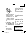
Cordless Circular Saw
Scie circulaire sans fi l
Sierra circular a batería
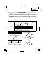
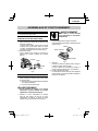
SAFETY INSTRUCTIONS AND INSTRUCTION MANUAL
WARNING
IMPROPER OR UNSAFE use of this power tool can result in death or serious bodily injury!
This manual contains important information about product safety. Please read and
understand this manual BEFORE operating the power tool. Please keep this manual
available for other users and owners before they use the power tool. This manual should be
stored in safe place.
INSTRUCTIONS DE SECURITE ET MODE D’EMPLOI
AVERTISSEMENT
Une utilisation INCORRECTE OU DANGEREUSE de cet outil motorisé peut entraîner la
mort ou de sérieuses blessures corporelles!
Ce mode d’emploi contient d’importantes informations à propos de la sécurité de ce produit.
Prière de lire et de comprendre ce mode d’emploi AVANT d’utiliser l’outil motorisé. Garder ce
mode d’emploi à la disponibilité des autres utilisateurs et propriétaires avant qu’ils utilisent
l’outil motorisé. Ce mode d’emploi doit être conservé dans un endroit sûr.
INSTRUCCIONES DE SEGURIDAD Y MANUAL DE INSTRUCCIONES
ADVERTENCIA
¡La utilización INAPROPIADA O PELIGROSA de esta herramienta eléctrica puede resultar
en lesiones de gravedad o la muerte!
Este manual contiene información importante sobre la seguridad del producto. Lea y
comprenda este manual ANTES de utilizar la herramienta eléctrica. Guarde este manual
para que puedan leerlo otras personas antes de utilizar la herramienta eléctrica. Este
manual debe ser guardado en un lugar seguro.
Designed for operating in USA & Canada only.
When this product is used in areas other than the USA & Canada,
we cannot guarantee the product quality and performance.

English
Page Page
Français
Page Page
Español
Página Página
TABLE DES MATIÈRES
ÍNDICE
CONTENTS
IMPORTANT SAFETY INFORMATION ..................... 3
MEANINGS OF SIGNAL WORDS ............................. 3
SAFETY........................................................................ 3
GENERAL POWER TOOL SAFETY WARNINGS ..... 3
CIRCULAR SAW SAFETY WARNINGS .................... 5
SPECIFIC SAFETY RULES ....................................... 6
IMPORTANT SAFETY INSTRUCTIONS FOR
BATTERY CHARGER ........................................ 6
IMPORTANT SAFETY INSTRUCTIONS FOR USE
OF THE BATTERY AND BATTERY CHARGER
... 7
CAUTION ON LITHIUM-ION BATTERY .................... 8
REGARDING LITHIUM-ION BATTERY
TRANSPORTATION .......................................... 9
USB DEVICE CONNECTION PRECAUTIONS ......... 9
FUNCTIONAL DESCRIPTION .................................. 10
NAME OF PARTS .................................................... 10
SPECIFICATIONS ................................................... 11
ASSEMBLY AND OPERATION ................................. 13
APPLICATIONS ....................................................... 13
REMOVAL AND INSTALLATION METHOD OF
BATTERY ......................................................... 13
CHARGING METHOD ............................................. 13
PRIOR TO OPERATION .......................................... 15
ADJUSTING THE SAW PRIOR TO USE ................. 16
OPERATION ............................................................ 18
MAINTENANCE AND INSPECTION ......................... 23
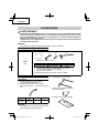
ACCESSORIES ......................................................... 25
STANDARD ACCESSORIES .................................. 25
OPTIONAL ACCESSORIES .................................... 25
PART LIST ................................................................. 76
INFORMATIONS IMPORTANTES DE SÉCURITÉ ... 26
SIGNIFICATION DES MOTS D’AVERTISSEMENT... 26
SECURITE ................................................................. 26
AVERTISSEMENTS DE SÉCURITÉ GÉNÉRAUX
CONCERNANT LES OUTILS ÉLECTRIQUES... 26
AVERTISSEMENTS DE SÉCURITÉ RELATIFS
À LA SCIE CIRCULAIRE .................................. 28
REGLES DE SECURITE SPECIFIQUES ................. 29
CONSIGNES DE SÉCURITÉ IMPORTANTES
POUR LE CHARGEUR DE BATTERIE ............ 30
CONSIGNES DE SÉCURITÉ IMPORTANTES POUR
L’UTILISATION DE LA BATTERIE ET DU
CHARGEUR DE BATTERIE ............................. 31
PRÉCAUTIONS RELATIVES A LA BATTERIE
AU LITHIUM ION .............................................. 32
À PROPOS DU TRANSPORT DE LA BATTERIE
LITHIUM-ION ................................................... 33
PRÉCAUTIONS LORS DE LA CONNEXION DU
DISPOSITIF USB ............................................. 33
DESCRIPTION FONCTIONNELLE ........................... 34
NOM DES PARTIES ................................................ 34
SPECIFICATIONS ................................................... 35
ASSEMBLAGE ET FONCTIONNEMENT .................. 37
UTILISATIONS ........................................................ 37
MÉTHODE DE RETRAIT ET D’INSTALLATION
DE LA BATTERIE ............................................. 37
MÉTHODE DE RECHARGE .................................... 37
AVANT L’UTILISATION ........................................... 39
RÉGLAGE DE LA SCIE AVANT UTILISATION........ 41
UTILISATION ........................................................... 43
ENTRETIEN ET INSPECTION .................................. 48
ACCESSOIRES ......................................................... 50
ACCESSOIRES STANDARD .................................. 50
ACCESSOIRES EN OPTION................................... 50
LISTA DES PIÈCES ................................................... 76
INFORMACIÓN IMPORTANTE SOBRE
SEGURIDAD ................................................... 51
SIGNIFICADO DE LAS PALABRAS DE
SEÑALIZACIÓN .............................................. 51
SEGURIDAD .............................................................. 51
ADVERTENCIAS DE SEGURIDAD GENERAL
DE LA HERRAMIENTA ELÉCTRICA .............. 51
ADVERTENCIAS DE SEGURIDAD DE LA
SIERRA CIRCULAR ......................................... 53
NORMAS ESPECÍFICOS DE SEGURIDAD ............ 54
INSTRUCCIONES IMPORTANTES DE
SEGURIDAD PARA EL CARGADOR DE
BATERÍAS ........................................................ 55
INSTRUCCIONES IMPORTANTES DE SEGURIDAD
PARA LA BATERÍA Y EL CARGADOR DE
BATERÍAS ........................................................ 56
ADVERTENCIA DE LA BATERÍA DE LITIO............. 57
A PROPÓSITO DEL TRANSPORTE DE LA
BATERÍA DE IONES DE LITIO ......................... 58
PRECAUCIONES DE CONEXIÓN DEL
DISPOSITIVO USB .......................................... 58
DESCRIPCIÓN FUNCIONAL .................................... 59
NOMENCLATURA .................................................. 59
ESPECIFICACIONES .............................................. 60
MONTAJE Y OPERACIÓN ........................................ 62
APLICACIONES ...................................................... 62
MÉTODO DE EXTRACCIÓN E INSTALACIÓN DE
LA BATERÍA ..................................................... 62
MÉTODO DE CARGA ............................................. 62
ANTES DE LA OPERACIÓN ................................... 64
AJUSTE DE LA SIERRA ANTES DEL USO ............ 66
OPERACIÓN ........................................................... 68
MANTENIMIENTO E INSPECCIÓN .......................... 73
ACCESSORIOS ......................................................... 75
ACCESORIOS ESTÁNDAR .................................... 75
ACCESORIOS OPCIONALES ................................. 75
LISTA DE PIEZAS ..................................................... 76

IMPORTANT SAFETY INFORMATION
Read and understand all of the safety precautions, warnings and operating instructions in the Instruction Manual before
operating or maintaining this power tool.
Most accidents that result from power tool operation and maintenance are caused by the failure to observe basic safety
rules or precautions. An accident can often be avoided by recognizing a potentially hazardous situation before it occurs,
and by observing appropriate safety procedures.
Basic safety precautions are outlined in the “SAFETY” section of this Instruction Manual and in the sections which
contain the operation and maintenance instructions.
Hazards that must be avoided to prevent bodily injury or machine damage are identifi ed by WARNINGS on the power
tool and in this Instruction Manual.
NEVER use this power tool in a manner that has not been specifi cally recommended by HITACHI.
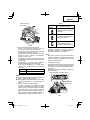
MEANINGS OF SIGNAL WORDS
WARNING indicates a potentially hazardous situations which, if ignored, could result in death or serious injury.
CAUTION indicates a potentially hazardous situations which, if not avoided, may result in minor or moderate injury, or
may cause machine damage.
NOTE emphasizes essential information.
SAFETY
GENERAL POWER TOOL SAFETY WARNINGS
WARNING
Read all safety warnings and all instructions.
Failure to follow the warnings and instructions may result in electric shock, fi re and/or serious injury.
Save all warnings and instructions for future reference.
The term “power tool” in the warnings refers to your mains-operated (corded) power tool or battery-operated
(cordless) power tool.
1) Work area safety
a) Keep work area clean and well lit.
Cluttered or dark areas invite accidents.
b) Do not operate power tools in explosive
atmospheres, such as in the presence of
fl ammable liquids, gases or dust.
Power tools create sparks which may ignite the
dust or fumes.
c) Keep children and bystanders away while
operating a power tool.
Distractions can cause you to lose control.
2) Electrical safety
a) Power tool plugs must match the outlet.
Never modify the plug in any way.
Do not use any adapter plugs with earthed
(grounded) power tools.
Unmodifi ed plugs and matching outlets will reduce
risk of electric shock.
b) Avoid body contact with earthed or grounded
surfaces such as pipes, radiators, ranges and
refrigerators.
There is an increased risk of electric shock if your
body is earthed or grounded.
c) Do not expose power tools to rain or wet
conditions.
Water entering a power tool will increase the risk
of electric shock.
d) Do not abuse the cord. Never use the cord for
carrying, pulling or unplugging the power tool.
Keep cord away from heat, oil, sharp edges or
moving parts.
Damaged or entangled cords increase the risk of
electric shock.
e) When operating a power tool outdoors, use
an extension cord suitable for outdoor use.
Use of a cord suitable for outdoor use reduces the
risk of electric shock.
f) If operating a power tool in a damp location
is unavoidable, use a residual current device
(RCD) protected supply.
Use of an RCD reduces the risk of electric shock.
3) Personal safety
a) Stay alert, watch what you are doing and use
common sense when operating a power tool.
Do not use a power tool while you are tired
or under the infl uence of drugs, alcohol or
medication.
3
English

A moment of inattention while operating power
tools may result in serious personal injury.
b) Use personal protective equipment. Always
wear eye protection.
Protective equipment such as dust mask, non-skid
safety shoes, hard hat, or hearing protection used
for appropriate conditions will reduce personal
injuries.
c) Prevent unintentional starting. Ensure the
switch is in the off -position before connecting
to power source and/or battery pack, picking
up or carrying the tool.
Carrying power tools with your fi nger on the switch
or energising power tools that have the switch on
invites accidents.
d) Remove any adjusting key or wrench before
turning the power tool on.
A wrench or a key left attached to a rotating part of
the power tool may result in personal injury.
e) Do not overreach. Keep proper footing and
balance at all times.
This enables better control of the power tool in
unexpected situations.
f) Dress properly. Do not wear loose clothing or
jewellery. Keep your hair, clothing and gloves
away from moving parts.
Loose clothes, jewellery or long hair can be caught
in moving parts.
g) If devices are provided for the connection
of dust extraction and collection facilities,
ensure these are connected and properly
used.
Use of dust collection can reduce dust-related
hazards.
4) Power tool use and care
a) Do not force the power tool. Use the correct
power tool for your application.
The correct power tool will do the job better and
safer at the rate for which it was designed.
b) Do not use the power tool if the switch does
not turn it on and off .
Any power tool that cannot be controlled with the
switch is dangerous and must be repaired.
c) Disconnect the plug from the power source
and/or the battery pack from the power tool
before making any adjustments, changing
accessories, or storing power tools.
Such preventive safety measures reduce the risk
of starting the power tool accidentally.
d) Store idle power tools out of the reach of
children and do not allow persons unfamiliar
with the power tool or these instructions to
operate the power tool.
Power tools are dangerous in the hands of
untrained users.
e) Maintain power tools. Check for misalignment
or binding of moving parts, breakage of parts
and any other condition that may aff ect the
power tool’s operation.
If damaged, have the power tool repaired
before use.
Many accidents are caused by poorly maintained
power tools.
f) Keep cutting tools sharp and clean.
Properly maintained cutting tools with sharp
cutting edges are less likely to bind and are easier
to control.
g) Use the power tool, accessories and tool bits
etc. in accordance with these instructions,
taking into account the working conditions and
the work to be performed.
Use of the power tool for operations diff erent
from those intended could result in a hazardous
situation.
5) Battery tool use and care
a) Recharge only with the charger specifi ed by
the manufacturer.
A charger that is suitable for one type of battery
pack may create a risk of fi re when used with
another battery pack.
b) Use power tools only with specifi cally
designated battery packs.
Use of any other battery packs may create a risk of
injury and fi re.
c) When battery pack is not in use, keep it away
from other metal objects like paper clips,
coins, keys, nails, screws, or other small metal
objects, that can make a connection from one
terminal to another.
Shorting the battery terminals together may cause
burns or a fi re.
d) Under abusive conditions, liquid may be
ejected from the battery; avoid contact. If
contact accidentally occurs, fl ush with water.
If liquid contacts eyes, additionally seek
medical help.
Liquid ejected from the battery may cause irritation
or burns.
6) Service
a) Have your power tool serviced by a
qualifi ed repair person using only identical
replacement parts.
This will ensure that the safety of the power tool is
maintained.
– WARNING –
To reduce the risk of injury, user must read
instruction manual.
4
English

WARNING:
Some dust created by power sanding, sawing,
grinding, drilling, and other construction activities
contains chemicals known to the State of California
to cause cancer, birth defects or other reproductive
harm. Some examples of these chemicals are:
●
Lead from lead-based paints,
●
Crystalline silica from bricks and cement and other
masonry products, and
●
Arsenic and chromium from chemically-treated
lumber.
Your risk from these exposures varies, depending on
how often you do this type of work. To reduce your
exposure to these chemicals: work in a well ventilated
area, and work with approved safety equipment, such
as those dust masks that are specially designed to
fi lter out microscopic particles.
CIRCULAR SAW SAFETY WARNINGS
Cutting procedures
a) DANGER: Keep hands away from cutting
area and the blade. Keep your second hand on
auxiliary handle, or motor housing.
If both hands are holding the saw, they cannot be cut
by the blade.
b) Do not reach underneath the workpiece.
The guard cannot protect you from the blade below
the workpiece.
c) Adjust the cutting depth to the thickness of the
workpiece.
Less than a full tooth of the blade teeth should be
visible below the workpiece.
d) Never hold piece being cut in your hands or
across your leg. Secure the workpiece to a stable
platform.
It is important to support the work properly to minimize
body exposure, blade binding, or loss of control.
e) Hold the power tool by insulated gripping
surfaces only, when performing an operation
where the cutting tool may contact hidden wiring.
Contact with a “live” wire will also make exposed
metal parts of the power tool “live” and could give the
operator an electric shock.
f) When ripping always use a rip fence or straight
edge guide.
This improves the accuracy of cut and reduces the
chance of blade binding.
g) Always use blades with correct size and shape
(diamond versus round) of arbour holes.
Blades that do not match the mounting hardware of
the saw will run eccentrically, causing loss of control.
h) Never use damaged or incorrect blade washers
or bolt.
The blade washers and bolt were specially designed
for your saw, for optimum performance and safety of
operation.
Kickback causes and related warnings
– kickback is a sudden reaction to a pinched, bound or
misaligned saw blade, causing an uncontrolled saw to lift
up and out of the workpiece toward the operator;
– when the blade is pinched or bound tightly by the kerf
closing down, the blade stalls and the motor reaction
drives the unit rapidly back toward the operator;
– if the blade becomes twisted or misaligned in the cut, the
teeth at the back edge of the blade can dig into the top
surface of the wood causing the blade to climb out of the
kerf and jump back toward the operator.
Kickback is the result of saw misuse and/or incorrect
operating procedures or conditions and can be avoided by
taking proper precautions as given below.
a) Maintain a fi rm grip with both hands on the saw
and position your arms to resist kickback forces.
Position your body to either side of the blade,
but not in line with the blade.
Kickback could cause the saw to jump backwards,
but kickback forces can be controlled by the operator,
if proper precautions are taken.
b) When blade is binding, or when interrupting a
cut for any reason, release the trigger and hold
the saw motionless in the material until the blade
comes to a complete stop.
Never attempt to remove the saw from the work
or pull the saw backward while the blade is in
motion or kickback may occur.
Investigate and take corrective actions to eliminate
the cause of blade binding.
c) When restarting a saw in the workpiece, centre
the saw blade in the kerf and check that saw
teeth are not engaged into the material.
If saw blade is binding, it may walk up or kickback
from the workpiece as the saw is restarted.
d) Support large panels to minimise the risk of
blade pinching and kickback.
Large panels tend to sag under their own weight.
Supports must be placed under the panel on both
sides, near the line of cut and near the edge of the
panel.
e) Do not use dull or damaged blades.
Unsharpened or improperly set blades produce
narrow kerf causing excessive friction, blade binding
and kickback.
f) Blade depth and bevel adjusting locking levers
must be tight and secure before making cut.
If blade adjustment shifts while cutting, it may cause
binding and kickback.
g) Use extra caution when sawing into existing
walls or other blind areas.
The protruding blade may cut objects that can cause
kickback.
5
English

6. Keep all screws, bolts and covers tightly in place.
Keep all screws, bolts, and plates tightly mounted.
Check their condition periodically.
7. Do not use power tools if the plastic housing or
handle is cracked.
Cracks in the tool’s housing or handle can lead to
electric shock. Such tools should not be used until
repaired.
8. Blades and accessories must be securely
mounted to the tool.
Prevent potential injuries to yourself or others. Blades,
cutting implements and accessories which have been
mounted to the tool should be secure and tight.
9. Carefully handle power tools.
Should a power tool be dropped or struck against
hard materials inadvertently, it may be deformed,
cracked, or damaged.
10. Do not wipe plastic parts with solvent.
Solvents such as gasoline, thinner benzine, carbon
tetrachloride, and alcohol may damage and crack
plastic parts. Do not wipe them with such solvents.
Wipe plastic parts with a soft cloth lightly dampened
with soapy water and dried thoroughly.
11. Keep motor air vent clean.
The tool’s motor air vent must be kept clean so that
air can freely fl ow at all times. Check for dust build-up
frequently.
12. NEVER leave tool running unattended. Turn
power off .
Don’t leave tool until it comes to a complete stop.
13. NEVER touch the blade with bare hands after
operation.
14. For this mode, the saw blades should be 165 mm.
15. Because the cordless circular saw operates by
battery power, be aware of the fact that it can begin to
operate at any time.
16. When working at elevated locations, clear the area of
other people and aware of conditions below you.
17. Do not give a strong shock to the switch panel or
break it. It may lead to a trouble.
IMPORTANT SAFETY INSTRUCTIONS
FOR BATTERY CHARGER
WARNING
Death or serious bodily injury could result from
improper or unsafe use of battery chargers.
To avoid these risks, follow these basic safety
instructions:
READ ALL INSTRUCTIONS
1. This manual contains important safety and operating
instructions for battery charger Model UC18YSL3.
2. Before using battery charger, read all instructions
and cautionary markings on (1) battery charger, (2)
battery, and (3) product using battery.
Lower guard function
a) Check lower guard for proper closing before each
use. Do not operate the saw if lower guard does
not move freely and close instantly. Never clamp
or tie the lower guard into the open position.
If saw is accidentally dropped, lower guard may be
bent.
Raise the lower guard with the retracting handle and
make sure it moves freely and does not touch the
blade or any other part, in all angles and depths of cut.
b) Check the operation of the lower guard spring.
If the guard and the spring are not operating
properly, they must be serviced before use.
Lower guard may operate sluggishly due to damaged
parts, gummy deposits, or a build-up of debris.
c) Lower guard should be retracted manually
only for special cuts such as “plunge cuts” and
“compound cuts”.
Raise lower guard by retracting handle and as soon
as blade enters the material, the lower guard must be
released.
For all other sawing, the lower guard should operate
automatically.
d) Always observe that the lower guard is covering
the blade before placing saw down on bench or
fl oor.
An unprotected, coasting blade will cause the saw to
walk backwards, cutting whatever is in its path.
Be aware of the time it takes for the blade to stop after
switch is released.
SPECIFIC SAFETY RULES
1. Never touch moving parts.
Never place your hands, fi ngers or other body parts
near the tool’s moving parts.
2. Never operate without all guards in place.
Never operate this tool without all guards or safety
features in place and in proper working order. If
maintenance or servicing requires the removal of a
guard or safety feature, be sure to replace the guard
or safety feature before resuming operation of the
tool.
3. Use right tool.
Don’t force small tool or attachment to do the job of a
heavy-duty tool.
Don’t use tool for purpose not intended —for
example— don’t use circular saw for cutting tree
limbs or logs.
4. Handle tool correctly.
Do not drop or throw the tool.
5. Defi nitions for symbols.
V .................volts
—
................. direct current
no ................no load speed
---/min ..........revolutions or reciprocation per minute
Hz ................hertz
A ..................amperes
6
English

3. To reduce risk of injury, charge HITACHI rechargeable
battery type BSL18 series. Other type of batteries
may burst causing personal injury and damage.
4. Use of an attachment not recommended or sold by
the battery charger manufacturer may result in a risk
of fi re, electric shock, or injury to persons.
5. To reduce risk of damage to electric plug and cord,
pull by plug when disconnecting battery charger.
6. Make sure cord is located so that it will not be stepped
on, tripped over, or otherwise subjected to damage or
stress.
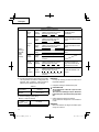
7. An extension cord should not be used unless
absolutely necessary. Use of improper extension
cord could result in a risk of fi re and electric shock.
If extension cord must be used make sure:
a. That blades of extension cord are the same
number, size, and shape as those of plug on
battery charger:
b. That extension cord is properly wired and in good
electrical condition; and
c. That wire size is large enough for AC ampere
rating of battery charger as specifi ed in Table 1.
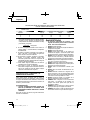
Table 1
RECOMMENDED MINIMUM AWG SIZE FOR
EXTENSION CORDS FOR BATTERY CHARGERS
AC Input Rating Amperes* AWG Size of Cord
Equal to or
greater than
but less
than
Length of Cord, Feet (Meter)
25 (7.5) 50 (15) 100 (30) 150 (45)
0 2 18 18 18 16
2 3 18 18 16 14
3 4 18 18 16 14
* If the input rating of a battery charger is given in watts
rather than in amperes, the corresponding ampere
rating is to be determined by dividing the wattage
rating by the voltage rating–for example:
1,250 watts
= 10 amperes
125 volts
8. Do not operate battery charger with damaged cord or
plug-replace them immediately.
9. Do not operate battery charger if it has received a
sharp blow, been dropped, or otherwise damaged in
any way; take it to a qualifi ed serviceman.
10. Do not disassemble battery charger and the battery;
take it to a qualifi ed serviceman when service or
repair is required. Incorrect reassembly may result in
a risk of electric shock or fi re.
11. You must charge the battery before you can use the
power tool.
12. To reduce risk of electric shock, unplug the charger
from the electrical outlet when not in use, as well as
before maintenance or cleaning.
IMPORTANT SAFETY INSTRUCTIONS
FOR USE OF THE BATTERY AND
BATTERY CHARGER
You must charge the battery before you can use the power
tool. Before using the model UC18YSL3 battery charger,
be sure to read all instructions and cautionary statements
on it, the battery and in this manual.
CAUTION
USE ONLY HITACHI BATTERY TYPES BSL18
SERIES. OTHER TYPES OF BATTERIES MAY
BURST AND CAUSE INJURY!
Follow these instructions to avoid the risk of injury:
WARNING:
Improper use of the battery
or battery charger can lead to
serious injury. To avoid these
injuries:
1. NEVER disassemble the battery.
2. NEVER incinerate the battery, even if it is damaged or
is completely worn out. The battery can explode in a
fi re.
3. NEVER short-circuit the battery.
4. NEVER insert any objects into the battery charger’s
air vents. Electric shock or damage to the battery
charger may result.
5. NEVER charge outdoors. Keep the battery away
from direct sunlight and use only where there is low
humidity and good ventilation.
6. NEVER charge when the temperature is below 14°F
(-10°C) or above 104°F (40°C).
7. NEVER connect two battery chargers together.
8. NEVER insert foreign objects into the hole for the
battery or the battery charger.
9. NEVER use a booster transformer when charging.
10. NEVER use DC power to charge.
7
English

11. NEVER store the battery or battery charger in places
where the temperature may reach or exceed 104°F
(40°C) such as inside metal box or car.
12. NEVER expose the battery or battery charger to rain
or wet conditions
13. ALWAYS operate charger on standard household
electrical power (120 volts). Using the charger on any
other voltage may overheat and damage the charger.
14. ALWAYS wait at least 15 minutes between charges to
avoid overheating the charger.
15. ALWAYS disconnect the power cord from its
receptacle when the charger is not in use.
CAUTION ON LITHIUM-ION BATTERY
To extend the lifetime, the lithium-ion battery equips with
the protection function to stop the output.
In the cases of 1 to 3 described below, when using this
product, even if you are pulling the switch, the motor may
stop. This is not the trouble but the result of protection
function.
1. When the battery power remaining runs out, the motor
stops.
In such case, charge it up immediately.
2. If the tool is overloaded, the motor may stop. In this
case, release the switch of tool and eliminate causes
of overloading. After that, you can use it again.
3. If the battery is overheated under overload work, the
battery power may stop.
In this case, stop using the battery and let the battery
cool. After that, you can use it again.
Furthermore, please heed the following warning and
caution.
WARNING
In order to prevent any battery leakage, heat generation,
smoke emission, explosion and ignition beforehand,
please be sure to heed the following precautions.
1. Make sure that swarf and dust do not collect on the
battery.
○
During work make sure that swarf and dust do not fall
on the battery.
○
Make sure that any swarf and dust falling on the power
tool during work do not collect on the battery.
○
Do not store an unused battery in a location exposed
to swarf and dust.
○
Before storing a battery, remove any swarf and dust
that may adhere to it and do not store it together with
metal parts (screws, nails, etc.).
2. Do not pierce battery with a sharp object such as a
nail, strike with a hammer, step on, throw or subject
the battery to severe physical shock.
3. Do not use an apparently damaged or deformed
battery.
4. Do not use the battery in reverse polarity.
5. Do not connect directly to an electrical outlets or car
cigarette lighter sockets.
6. Do not use the battery for a purpose other than those
specifi ed.
7. If the battery charging fails to complete even when a
specifi ed recharging time has elapsed, immediately
stop further recharging.
8. Do not put or subject the battery to high temperatures
or high pressure such as into a microwave oven,
dryer, or high pressure container.
9. Keep away from fi re immediately when leakage or foul
odor are detected.
10. Do not use in a location where strong static electricity
generates.
11. If there is battery leakage, foul odor, heat generated,
discolored or deformed, or in any way appears
abnormal during use, recharging or storage,
immediately remove it from the equipment or battery
charger, and stop use.
12. Do not immerse the battery or allow any fl uids to fl ow
inside. Conductive liquid ingress, such as water, can
cause damage resulting in fi re or explosion. Store your
battery in a cool, dry place, away from combustible
and fl ammable items. Corrosive gas atmospheres
must be avoided.
CAUTION
1. If liquid leaking from the battery gets into your eyes,
do not rub your eyes and wash them well with fresh
clean water such as tap water and contact a doctor
immediately.
If left untreated, the liquid may cause eye-problems.
2. If liquid leaks onto your skin or clothes, wash well with
clean water such as tap water immediately.
There is a possibility that this can cause skin irritation.
3. If you fi nd rust, foul odor, overheating, discolor,
deformation, and/or other irregularities when using
the battery for the fi rst time, do not use and return it to
your supplier or vendor.
WARNING
If an electrically conductive foreign object enters the
terminals of the lithium ion battery, a short-circuit may
occur resulting in the risk of fi re. Please observe the
following matters when storing the battery.
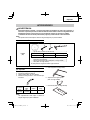
○
Do not place electrically conductive cuttings,
nails, steel wire, copper wire or other wire in the
storage case.
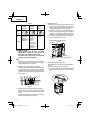
○
Either install the battery in the power tool or store
by securely pressing into the battery cover until
the ventilation holes are concealed to prevent
short-circuits (See Fig. 1).
8
English

REGARDING LITHIUM-ION BATTERY
TRANSPORTATION
When transporting a lithium-ion battery, please observe
the following precautions.
WARNING
Notify the transporting company that a package
contains a lithium-ion battery, inform the company
of its power output and follow the instructions of the
transportation company when arranging transport.
●
Lithium-ion batteries that exceed a power output
of 100Wh are considered to be in the freight
classifi cation of Dangerous Goods and will
require special application procedures.
●
For transportation abroad, you must comply with
international law and the rules and regulations of
the destination country.
Wh
Power Output
2 to 3 digit number
Fig. 1
USB DEVICE CONNECTION
PRECAUTIONS
When an unexpected problem occurs, the data in a USB
device connected to this product may be corrupted or lost.
Always make sure to back up any data contained in the
USB device prior to use with this product.
Please be aware that our company accepts absolutely no
responsibility for any data stored in a USB device that is
corrupted or lost, nor for any damage that may occur to a
connected device.
SAVE THESE INSTRUCTIONS
AND
MAKE THEM AVAILABLE TO OTHER USERS
AND
OWNERS OF THIS TOOL!
9
English

FUNCTIONAL DESCRIPTION
NOTE
The information contained in this Instruction Manual is designed to assist you in the safe operation and maintenance
of the power tool.
NEVER operate, or attempt any maintenance on the tool unless you have fi rst read and understood all safety
instructions contained in this manual.
Some illustrations in this Instruction Manual may show details or attachments that diff er from those on your own
power tool.
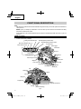
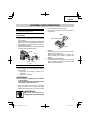
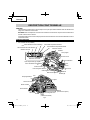
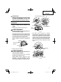
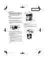
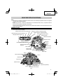
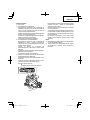
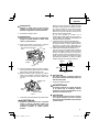
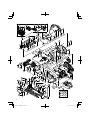
NAME OF PARTS
1. Cordless Circular Saw (C18DBAL)
Lock lever
Battery
(optional accessories)
LED Light
Hex. bar wrench 5 mm
Nameplate
Handle
Housing
Motor
(Inside the Housing)
Wing-bolt
Stopper lever
Link
Saw blade
Washer (B)
Base
Saw cover
Switch trigger
Lock-off button
Wing-bolt
Incline wing-nut
Cutting depth lever
Lower guard lever
Incline lever
Switch panel
Mode selector switch
Silent mode indicator lamp
Lighting mode switch
Lighting mode indicator lamp
Remaining battery indicator lamp
Remaining battery indicator switch
Guide piece
Sub handle
Lower guard
Left-hand bolt
Guide
Fig. 2
10
English

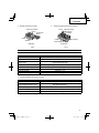
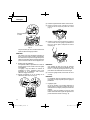
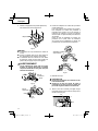
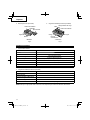
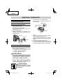
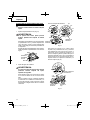
2. Battery (optional accessories) 3. Battery Charger (optional accessories)
Ventilation holes
Latch
Terminals
Battery cover
Battery
<BSL1860> <UC18YSL3>
Nameplate
Cord
Guide rail
Charge indicator lamp
Ventilation holes
Body
Fig. 3 Fig. 4
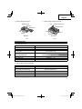
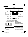
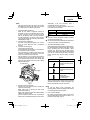
SPECIFICATIONS
1. Cordless Circular Saw
Model C18DBAL
Voltage 18 V
Motor DC brushless motor
No-load speed
4,100 /min (Power mode)
2,500 /min (Silent mode)
Blade Size 6-1/2" (165 mm) D × 5/8" (15.9 mm) H × 1/16" (1.6 mm) T
Max. Cutting Depth at 90° 2-19/32" (66 mm)
Max. Cutting Depth at 45° 1-49/64" (45 mm)
Max. Blade Angle Adjustable -5° – 45°
Weight (without battery) 6.0 lbs. (2.7 kg)
2. Battery Charger (optional accessories)
Model UC18YSL3
Input power source Single phase: AC 120 V 60 Hz
Charging time
(At a temperature of 68°F (20°C))
BSL1860 : Approx. 38 min
Charging voltage DC 14.4 – 18 V
Charging current DC 8.0 A
Weight 1.3 lbs. (0.6 kg)
NOTE: The charging time may vary according to temperature and power source voltage.
11
English

Electronic control
○
Soft-start
○
Overload protection
This protection feature cuts off the power to the motor
in the event of overloading of motor or a conspicuous
reduction in rotational speed during operation.
When the overload protection feature has been
activated, the motor may stop.
In this case, release the tool switch and eliminate
causes of overloading.
After that you can use it again.
○
Overheat protection
This protection feature cuts off the power to the motor
and stops the power tool in the event of overheating of
motor during operation.
When the overheat protection feature has been
activated, the motor may stop.
In this case, release the tool switch and cool it down in
a few minutes.
After that you can use it again.
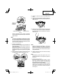
○
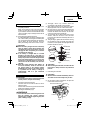
Rotation speed changeover function (Power mode /
Silent mode)
(Power mode / Silent mode switch function)
Each press of the Mode Selector Switch changes the
operating mode. (Fig. 5)
Mode selector switch
Silent mode indicator lamp
Fig. 5
Silent mode reduces maximum motor RPM enabling
effi cient work with less noise.
The Silent Mode Indicator Lamp lights in Silent mode.
When the load increases during Silent mode, the tool
will automatically switch to Power mode and revert
back to Silent mode when the load decreases.
In Power mode, no change is made to Silent mode
even when the load decreases.
NOTE
○
To enable mode changes, pull the switch once after
installing the battery.
○
Do not give a strong shock to the switch panel or
break it. It may lead to a trouble.
12
English

APPLICATIONS
○
Cutting various types of wood.
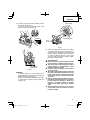
REMOVAL AND INSTALLATION METHOD
OF BATTERY
○
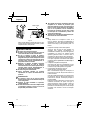
How to install the battery.
Align the battery with the groove in tool handle and
slip it into place.
Always insert it all the way until it locks in place with a
little click, If not, it may accidentally fall out of the tool,
causing injury to you or someone around you (Fig. 6).
○
How to remove the battery.
Withdraw battery from the tool handle while pressing
the latch (2 pcs) of the battery (Fig. 6).
Latch
Battery
Pull outInsert
Push
Handle
Fig. 6
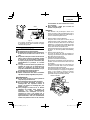
CHARGING METHOD
NOTE
Before plugging into the receptacle, make sure the
following points.
○
The power source voltage is stated on the
nameplate.
○
The cord is not damaged.
WARNING
Do not charge at voltage higher than indicated
on the nameplate.
If charged at voltage higher than indicated on the
nameplate, the charger will burn out.
1. Connect the charger’s power cord to a receptacle.
When the power cord is connected, the charge
indicator lamp will blink in red. (At 1-second intervals)
WARNING
Do not use the electrical cord if
damaged. Have it repaired immediately.
2. Insert the battery to the battery charger.
Firmly Insert the battery into the battery charger as
shown in Fig. 7.
Charge indicator lamp
Guide rail
Battery
Fig. 7
3. Charging
When inserting a battery in the charger, the charge
indicator lamp will blink in blue.
When the battery becomes fully recharged, the
charge indicator lamp will light up in green.(See
Table 2)
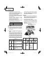
(1) Charge indicator lamp indication
The indications of the charge indicator lamp will be
as shown in Table 2, according to the condition of the
battery charger or the battery.
ASSEMBLY AND OPERATION
13
English

(2) Regarding the temperature of the rechargeable
battery.
The temperatures for rechargeable batteries are
as shown in the Table 3, and batteries that have
become hot should be cooled for a while before being
recharged.
Table 3
Rechargeable
batteries
Temperatures at which the battery
can be recharged
BSL1860
14°F – 122°F
(-10°C – 50°C)
(3) Regarding recharging time (At 68°F (20°C))
Table 4 Charging time
Charger
Battery
UC18YSL3
BSL1860 Approx. 38 min.
NOTE
The recharging time may vary according to the
ambient temperature.
4. Disconnect battery charger from the receptacle.
CAUTION
Do not pull the plug out of the receptacle by
pulling on the cord.
Make sure to grasp the plug when removing from
receptacle to avoid damaging cord.
5. Remove the battery from the battery charger.
Supporting the battery charger with hand, pull out the
battery from the battery charger.
NOTE
Be sure to pull out the battery from the battery charger
after use, and then keep it.
Regarding electric discharge in case of new
batteries, etc.
As the internal chemical substance of new batteries
and batteries that have not been used for an extended
period is not activated, the electric discharge might
be low when using them the fi rst and second time.
This is a temporary phenomenon, and normal time
required for recharging will be restored by recharging
the batteries 2 – 3 times.
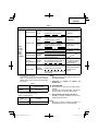
Table 2
Indications of the charge indicator lamp
Charge
indicator
lamp
(RED /
BLUE /
GREEN /
PURPLE)
Before
charging
Blinks
(RED)
Lights for 0.5 seconds. Does not light
for 0.5 seconds. (off for 0.5 seconds)
Plugged into power source
While
charging
Blinks
(BLUE)
Lights for 0.5 seconds. Does not light
for 1 second. (off for 1 second)
Battery capacity at less than
50%
Blinks
(BLUE)
Lights for 1 second. Does not light for
0.5 seconds. (off for 0.5 seconds)
Battery capacity at less than
80%
Lights
(BLUE)
Lights continuously
Battery capacity at more than
80%
Charging
complete
Lights
(GREEN)
Lights continuously
(Continuous buzzer sound: about
6 seconds)
Overheat
standby
Blinks
(RED)
Lights for 0.3 seconds. Does not light
for 0.3 seconds. (off for 0.3 seconds)
Battery overheated. Unable
to charge. (Charging will
commence when battery cools)
Charging
impossible
Flickers
(PURPLE)
Lights for 0.1 seconds. Does not light
for 0.1 seconds. (off for 0.1 seconds)
(Intermittent buzzer sound: about
2 seconds)
Malfunction in the battery or the
charger
14
English

How to make the batteries perform longer
(1) Recharge the batteries before they become
completely exhausted.
When you feel that the power of the tool becomes
weaker, stop using the tool and recharge its battery.
If you continue to use the tool and exhaust the electric
current, the battery may be damaged and its life will
become shorter.
(2) Avoid recharging at high temperatures.
A rechargeable battery will be hot immediately after
use. If such a battery is recharged immediately after
use, its internal chemical substance will deteriorate,
and the battery life will be shortened. Leave the
battery and recharge it after it has cooled for a while.
CAUTION
●
When the battery charger has been continuosly
used, the battery charger will be heated, thus
constituting the cause of the failures. Once the
charging has been completed, give 15 minutes
rest until the next charging.
●
If the battery is charged while it is heated
because it has been left for a long time in a
location subject to direct sunlight or because the
battery has just been used, the charge indicator
lamp of the charger lights for 0.3 seconds, does
not light for 0.3 seconds (off for 0.3 seconds). In
such a case, fi rst let the battery cool, then start
charging.
●
When the charge indicator lamp fl ickers (at
0.2–second intervals), check for and take out
any foreign objects in the charger’s battery
installation hole. If there are no foreign objects,
it is probable that the battery or charger is
malfunctioning. Take it to your authorized
Service Center.
PRIOR TO OPERATION
CAUTION
To avoid serious accident, ensure the switch is in
the OFF position, and pull out the battery.
1. Check the work area environment
Check the work area to make sure that it is clear of
debris and clutter.
Clear the area of unnecessary personnel. Ensure that
lighting and ventilation is adequate.
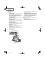
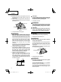
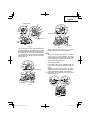
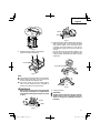
2. Mounting the Saw Blade (Fig. 8)
WARNING
If the left-hand bolt is worked using other tools
than the provided hex. wrench, excessive
tightening and insuffi cient tightening may take
place, resulting in injury.
(1) Thoroughly remove any sawdust which has
accumulated on the spindle, bolt and washers.
(2) Apply quality machine oil to the surfaces of washers
(B) and (A) which come into contact with the blade.
(3) As shown in Fig. 8, one side of the saw blade should
be fi tted to the projecting center of washer (A) which
matches the blade’s inner diameter, and the other
side to the concave side of washer (B).
(4) To ensure that the saw blade rotates in the correct
direction, make sure the arrow on the saw blade
points in the same direction indicated by the arrow on
the saw cover.
(5) Using the fi ngers, tighten the left-hand bolt securing
the saw blade as much as possible. Then press the
lock button, lock the spindle, and fully tighten the left-
hand bolt with the hex. wrench.
Left-hand bolt
Washer (A)
Spindle
Washer (B)
Concave
Saw blade
Fig. 8
CAUTION
After mounting the saw blade, reconfi rm that the
lock button is fi rmly secured in the prescribed
position.
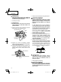
3. Dismounting the saw blade
CAUTION
Never touch the saw blade immediately after use.
The metal is hot and can easily burn your skin.
(1) Set the cutting volume at maximum, and place the
Circular Saw as shown in Fig. 9.
Hex. bar wrench 5 mm
Lock lever
Loosen
Fig. 9
15
English

(2) Depress the lock lever, lock the spindle, and remove
the left-hand bolt and washer (B) with the hex. bar
wrench 5 mm.
(3) While holding the lower guard lever to keep the lower
guard fully retracted into the saw cover, remove the
saw blade (Fig. 10).
Lower guard lever
Saw cover
Saw blade
Fig. 10
4. Check performance of lower guard
WARNING
Make absolutely sure that the lower guard is not
fi xed. Also, check and see if it can move smoothly.
If the saw blade is kept exposed, injury can result.
The lower guard (refer to Fig. 2) serves to protect your
body from coming into contact with the saw blade.
Make absolutely certain that the cover smoothly
performs to cover the saw blade. If the lower guard
should not move smoothly, never use it without
repairing it.
In such a case, get in touch with the store where you
bought the circular saw or the HITACHI AUTHORIZED
SERVICE CENTER for necessary repair.
5. Check for proper operation of the brake
This circular saw features an electric brake that
functions when the switch is released. Before using
the circular saw, ensure that the electric brake
functions properly. If it does not, bring the tool to a
HITACHI AUTHORIZED SERVICE CENTER.
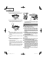
6. Prepare a wooden work bench (Fig. 11)
Since the saw blade will extend beyond the lower
surface of the lumber, place the lumber on a work
bench when cutting. If a square block is utilized
as a work bench, select level ground to ensure it is
properly stabilized. An unstable work bench will result
in hazardous operation.
BaseLumber
Work bench
Saw blade
Fig. 11
CAUTION
To avoid possible accident, always ensure that
the portion of lumber remaining after cutting is
securely anchored or held in position.
7. Check battery insertion
WARNING
If the battery is inserted while the power switch
is in the ON position, the power tool will start
operating immediately, inviting serious accident.
CAUTION
Until the battery locks in place with a little click,
if not, it may accidentally fall out of the tool
causing injury to you or someone around you.
ADJUSTING THE SAW PRIOR TO USE
CAUTION
Pull out battery before doing any adjusting.
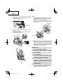
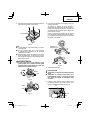
1. Adjusting the cutting depth (Fig. 12)
WARNING
If the lever is loose, injury can result. Tighten it
securely after adjustment.
To adjust cutting depth, loosen the cutting depth lever
and, while holding the base with one hand, move
the main body up and down to obtain the prescribed
cutting depth.
After adjusting to the prescribed cutting depth, tighten
the cutting depth lever securely.
Cutting depth lever
Base
Tighten
Loosen
Fig. 12
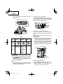
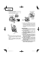
2. Adjusting the angle of inclination
WARNING
If the wing-nut is loose, injury can result. Tighten
it securely after adjustment.
You can incline saw blade from -5° to a maximum
angle of 45° in relation to the base.
As shown in Fig. 13 by loosening the incline lever
on the inclined gauge and incline wing-nut, the saw
blade may be inclined to a maximum angle of 45° in
relation to the base.
16
English

15
30
0
Incline wing-nut
Incline
lever
Tighten
Loosen
Inclined gauge
45°
30°
15°
0°
Tighten
Loosen
Fig. 13
To use at an angle of -5°, fi rst loosen the cutting depth
lever and minimize the cutting depth of the saw blade.
Next, loosen the incline lever and the incline wing-nut,
turning the stopper lever in the direction indicated as A
(Fig.14). Tilting the main unit in the direction indicated
as B, fasten the unit with the incline lever and incline
wing-nut (Fig. 15).
Incline wing-nut
Incline lever
Loosen
A
Loosen
Stopper lever
Fig. 14
Tighten
Tighten
Incline wing-nut
Incline lever Stopper lever
B
Fig. 15
Always ensure that the wing-nut is thoroughly
tightened after making the desired adjustment.
NOTE
Values of the inclined gauge provided on the base
merely serve as a rough guideline. For cutting
operation at an inclined precise angle, use the circular
saw after adjusting the angle between the base and
the saw blade with a protractor, etc.
3. Fine tuning of parallelism
It is possible to fi ne-tune the parallelism of the saw
blade to the base using the parallelism adjustment
screw.
Adjustment has already been made at the time of
shipment from the factory. However, in the unlikely
event of parallelism being faulty, adjust as follows.
(1) Unfasten only the mounting screws of the saw cover
hinge portion (Fig. 16).
Fig. 16
17
English

(2) Retract the lower guard into the saw cover.
(3) Insert wood chip in the rear side of the saw blade
base, and mark the position on the base (Fig. 17).
Fig. 17
(4) Move the marked wood chip to the front of the base,
and turn the parallelism adjustment screw so that the
marking corresponds to the base side (Fig. 18).
Fig. 18
NOTE
After parallelism adjustment, if the saw cover hinge
portion is loose, tighten the M5 U-Nut. Do not over
tighten the nut as this may result in deformation of the
bevel plate.
(5) After adjustment, fasten the mounting screws tightly
in place.
NOTE
Parallelism may be slightly faulty if the cutting depth is
adjusted after parallelism adjustment.
4. Adjusting the guide piece
On the circular saw, it is possible to make fi ne
adjustment of the fi xing position of the guide piece,
where the saw blade and the premarked line are to be
aligned.
When the saw is shipped from the factory, the linear
portion of a front scale on the guide piece is aligned
with the central position of the saw blade (Fig. 19).
Guide piece
Fig. 19
Loosen the fi xed M4 screw on the guide piece, should
the fi xing position be wrong, and make necessary
adjustment of the position.
OPERATION
WARNING
●
Never touch the moving parts.
●
Never operate the circular saw with the saw
blade turned upward or to the side.
●
Do not fi x and secure the lock-off button.
Besides, keep your fi nger off the switch trigger
when the circular saw is being carried around.
Otherwise, the main body switch can be
inadvertently turned ON, resulting in unexpected
accidents.
●
Keep the light ON during cutting operation only.
If it is lit ON in other cases, the main body switch
can be inadvertently turned ON, resulting in
unexpected accidents.
●
Do not use any abrasive wheels.
●
Use only blade diameter specifi ed on the product
nameplate.
CAUTION
●
Don’t remove circular saw from workpiece during
a cut while the saw blade is moving.
●
Pull out the battery after completing operation.
●
Do not look directly into the light from the LED
light. Continuous and direct exposure to the light
from the LED light can injure your eyes.
●
To extend the lifetime, the lithium-ion battery
equips with the protection function to stop the
output. Therefore, if the tool is overloaded, the
motor may stop. However, this is not the trouble
but the result of protection function. In this case,
release the switch of tool and eliminate the
causes of overloading.
●
Before use, check to see if the lock-off button
moves smoothly.
18
English

NOTE
Take care not to lock the motor. If the motor is locked,
immediately turn the power off . If the motor is locked
for a while, the motor or battery may be burnt.
1. Check if saw blade is tightened
While the saw blade is tightened securely for
immediate use when it is assembled at the factory,
be sure to check it out again for caution’s sake. A
bolt can be tightened when it is turned clockwise.
Use the provided hex. bar wrench 5 mm to check it
out. For further details, refer to the item of [PRIOR TO
OPERATION] on Page 15.
2. Check if the lever is tightened
If the lever to adjust cutting depth (Fig. 12) is loose,
injury can result. Make sure that it is tightened
securely.
3. Operation of switch (Fig. 20)
(switch trigger and light switch)
For safe operation of the machine, a “lock-off button”
is provided on the side of a handle.
If the “switch trigger” is pulled in a state where “lock-
off button” is pressed in the direction of the arrow
mark, the main switch can be turned ON.
After the switch is on, the saw blade will continue to
operate as long as you pull on the switch trigger, even
if you release the lock-off button. Also, the LED light
will remain lit for Always-ON mode as well as during
SW interlocked mode.
Switch trigger
Lock-off button
Fig. 20
4. About the mode select function
Each time the mode selector switch is pushed, the
operation mode changes.
When Silent mode is selected, the Silent mode
indicator lamp lights up.
Silent mode reduces maximum motor RPM enabling
effi cient work with less noise.
If the load increases while the motor is operating in
Silent mode, it automatically changes to Power mode.
Additionally, if the load decreases again, it
automatically returns to Silent mode.
In Power mode, no change is made to Silent mode
even when the load decreases.
Mode No-load speed
Power 4,100 /min
Silent 2,500 /min
NOTE
●
The mode will only change after a battery is installed
and the switch is pulled once.
●
The current mode will be maintained even if the switch
is on/off , or the battery is removed/reinserted.
5. About Remaining Battery Indicator
When pressing the remaining battery indicator switch,
the remaining battery indicator lamp lights and the
battery remaining power can be checked. When
releasing your fi nger from the remaining battery
indicator switch, the remaining battery indicator lamp
goes off . The Table 4 shows the state of remaining
battery indicator lamp and the battery remaining
power.
Table 4
State of lamp Battery Remaining Power
The battery remaining power
is enough.
The battery remaining power
is a half.
The battery remaining power
is nearly empty.
Re-charge the battery
soonest possible.
As the remaining battery indicator shows somewhat
diff erently depending on ambient temperature and
battery characteristics, read it as a reference.
NOTE
To save the battery power consumption, the
remaining battery indicator lamp lights while pressing
the remaining battery indicator switch.
6. How to use the LED light
By pressing the light selector switch on the switch
panel, the LED light mode changes as Table 5. It is
indicated by green lamp. (Fig. 21)
19
English

To prevent the battery power consumption, turn off the
LED light frequently.
Remaining battery indicator lamp
Switch panel
Light section
switch
LED Light
Fig. 21
Table 5
Always-ON
mode
SW
interlocked
mode
Always-OFF
mode
Panel
display
State
Always ON
(turn off after
2 minutes)
Light only
SW-ON
(Automatically
goes out
approximately
10 seconds
after the
switch is
released)
Always OFF
CAUTION
Wipe off any dirt or grime attached to the lens of
the LED light with a soft cloth, being careful not
to scratch the lens.
Scratches on the lens of the LED light can result
in decreased brightness.
NOTE
To prevent the battery power consumption caused by
forgetting to turn off the LED light, the light goes off
automatically in about 2 minutes.
7. Attaching the guide (sold separately)
Slide the guide through the front hole on the side of
the base (the cut-off side). Move the guide to the right
or left to adjust the cutting position, and tighten the
wing-bolt at the front to fasten the guide.
Guide
Wing-bolt
Fig. 22
8. Attaching the long guide (sold separately)
You can cut at a greater degree of parallel angle
against the end face of materials than the regular
guide.
When using the long guide, use the wing-bolts at the
front and rear.
(1) Normal installation
a) Slide the front and rear guide bars through the
holes on the base side and move the long guide to
the right or left to adjust the cutting position.
b) Press the front guide bar against the indicated
direction and tighten the front wing-bolt. Then,
tighten the rear wing-bolt to fasten the guide bar.
c) Lay the front of the long guide along the material to
cut.
Long guide
Front wing-bolt
Front guide bar
Rear guide bar
Rear wing-bolt
Fig. 23
(2) Installation to the housing side
Use by re-installing the two front and rear guide bars.
a) Remove the two screws of the long guide.
b) With the protrusions of the long guide pointing
downwards, re-attach the two guide bars.
20
English
La page est en cours de chargement...
La page est en cours de chargement...
La page est en cours de chargement...
La page est en cours de chargement...
La page est en cours de chargement...
La page est en cours de chargement...
La page est en cours de chargement...
La page est en cours de chargement...
La page est en cours de chargement...
La page est en cours de chargement...
La page est en cours de chargement...
La page est en cours de chargement...
La page est en cours de chargement...
La page est en cours de chargement...
La page est en cours de chargement...
La page est en cours de chargement...
La page est en cours de chargement...
La page est en cours de chargement...
La page est en cours de chargement...
La page est en cours de chargement...
La page est en cours de chargement...
La page est en cours de chargement...
La page est en cours de chargement...
La page est en cours de chargement...
La page est en cours de chargement...
La page est en cours de chargement...
La page est en cours de chargement...
La page est en cours de chargement...
La page est en cours de chargement...
La page est en cours de chargement...
La page est en cours de chargement...
La page est en cours de chargement...
La page est en cours de chargement...
La page est en cours de chargement...
La page est en cours de chargement...
La page est en cours de chargement...
La page est en cours de chargement...
La page est en cours de chargement...
La page est en cours de chargement...
La page est en cours de chargement...
La page est en cours de chargement...
La page est en cours de chargement...
La page est en cours de chargement...
La page est en cours de chargement...
La page est en cours de chargement...
La page est en cours de chargement...
La page est en cours de chargement...
La page est en cours de chargement...
La page est en cours de chargement...
La page est en cours de chargement...
La page est en cours de chargement...
La page est en cours de chargement...
La page est en cours de chargement...
La page est en cours de chargement...
La page est en cours de chargement...
La page est en cours de chargement...
La page est en cours de chargement...
La page est en cours de chargement...
La page est en cours de chargement...
La page est en cours de chargement...
-
 1
1
-
 2
2
-
 3
3
-
 4
4
-
 5
5
-
 6
6
-
 7
7
-
 8
8
-
 9
9
-
 10
10
-
 11
11
-
 12
12
-
 13
13
-
 14
14
-
 15
15
-
 16
16
-
 17
17
-
 18
18
-
 19
19
-
 20
20
-
 21
21
-
 22
22
-
 23
23
-
 24
24
-
 25
25
-
 26
26
-
 27
27
-
 28
28
-
 29
29
-
 30
30
-
 31
31
-
 32
32
-
 33
33
-
 34
34
-
 35
35
-
 36
36
-
 37
37
-
 38
38
-
 39
39
-
 40
40
-
 41
41
-
 42
42
-
 43
43
-
 44
44
-
 45
45
-
 46
46
-
 47
47
-
 48
48
-
 49
49
-
 50
50
-
 51
51
-
 52
52
-
 53
53
-
 54
54
-
 55
55
-
 56
56
-
 57
57
-
 58
58
-
 59
59
-
 60
60
-
 61
61
-
 62
62
-
 63
63
-
 64
64
-
 65
65
-
 66
66
-
 67
67
-
 68
68
-
 69
69
-
 70
70
-
 71
71
-
 72
72
-
 73
73
-
 74
74
-
 75
75
-
 76
76
-
 77
77
-
 78
78
-
 79
79
-
 80
80


Hitachi C 18DBAL Safety Instructions And Instruction Manual
- Catégorie
- Outils électroportatifs
- Taper
- Safety Instructions And Instruction Manual
dans d''autres langues
- English: Hitachi C 18DBAL
- español: Hitachi C 18DBAL
Documents connexes
Autres documents
-
Worx WX530L Le manuel du propriétaire
-
DeWalt DCS575B Manuel utilisateur
-
-
-
DeWalt DCS566 Manuel utilisateur
-
Milwaukee V28 0730-20 Manuel utilisateur
-
-
-
-
 Erbauer ECS18-Li Manuel utilisateur
