
NORCOLD, Inc.
P.O. Box 4248
Sidney, OH 45365-4248
Part No. 639307A (2/19/18)
English
Owner’s Manual
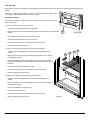
FIRE OR EXPLOSION HAZARD
If you smell gas or ammonia:
1. Open Windows
2. Do not attempt to light appliance.
3. Do not touch electrical switches.
4. Extinguish any open ame
5. Shut off fuel supply.
6. Evacuate immediately and call emergency services.
Failure to follow these instructions could result in re or explosion, which could cause
property damage, personal injury, or death.
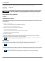
Improper installation, adjustment, alteration, service or maintenance
can cause injury or property damage. Refer to this manual. For
assistance or additional information, contact a qualied installer,
service agency, or the gas supplier.
FOR YOUR SAFETY
Do not store or use gasoline or other ammable vapors and liquid in the
vicinity of this or any other appliance.
WARNING
!
WARNING
!
Norcold Customer Support Dept.
Telephone: 800-543-1219
Fax: 734-769-2332
Web Site: www.norcold.com
For Polar 10 Series N10LX and NA10LX models: 10 cu.ft., 2-way R.V. refrigerators or with
Icemaker
Any letters following the above model numbers means a refrigerator option.

Owner’s Manual 2
Table of Contents
For dened warranty terms, please see the one page warranty statement included in the product information packet.
Safety Awareness ..................................................................................................................................................................................... 3
Safety Instructions ....................................................................................................................................................................................3
About Your Refrigerator ............................................................................................................................................................................ 4
Storage volume ........................................................................................................................................................................................4
Leveling .............................................................................................................................................................................................4
Operation during travel ...................................................................................................................................................................... 4
Food compartment ............................................................................................................................................................................4
Freezer compartment ........................................................................................................................................................................4
Crisper(s) ...........................................................................................................................................................................................4
Door bins ...........................................................................................................................................................................................4
Door bin slide ....................................................................................................................................................................................5
Adjustable shelves ............................................................................................................................................................................5
Door handles .....................................................................................................................................................................................6
Interior light........................................................................................................................................................................................6
Shut down .........................................................................................................................................................................................6
Moisture reduction heater..................................................................................................................................................................6
Temperature control system .............................................................................................................................................................. 6
Backup operating system ..................................................................................................................................................................6
Operating the Refrigerator Controls .........................................................................................................................................................7
Ignition and start up ........................................................................................................................................................................... 7
Air in the propane gas supply line .....................................................................................................................................................7
Automatic Mode operations...............................................................................................................................................................7
Manual AC Mode operations ............................................................................................................................................................. 8
Manual LP Gas mode ........................................................................................................................................................................8
Manual DC operations (3way regrigerators only) ..............................................................................................................................8
Shut down - All models ......................................................................................................................................................................8
Effects of HIgh Altitude on Propane Gas Operation .................................................................................................................................9
Effects of Freezing Temperatures on Refrigerator Operation ................................................................................................................... 9
Ice Maker (N1LXIM and NA10LXIM models) ...........................................................................................................................................9
Ice maker operation...........................................................................................................................................................................9
Refrigerator Care Checklist ....................................................................................................................................................................10
Defrosting ...............................................................................................................................................................................................10
Cleaning ................................................................................................................................................................................................. 11
Interior ............................................................................................................................................................................................. 11
Drip tray ........................................................................................................................................................................................... 12
Glass shelf ....................................................................................................................................................................................... 12
Door Sealing....................................................................................................................................................................................12
Refrigerator Storage ...............................................................................................................................................................................13
Ice Maker Storage (N109XIM and N109XIMXX models) .......................................................................................................................13
Refrigerator Maintenance Checklist .......................................................................................................................................................14
Refrigerator Maintenance ................................................................................................................................................................ 15
Gas ame appearance ....................................................................................................................................................................15
Remove and clean the burner orice ..............................................................................................................................................15
Remove the Refrigerator ........................................................................................................................................................................16
Reinstall the Refrigerator ........................................................................................................................................................................ 17
Replacement Parts ................................................................................................................................................................................17
Wiring Pictorial........................................................................................................................................................................................18
Wiring Schematic....................................................................................................................................................................................19
Fault Codes ............................................................................................................................................................................................20

Owner’s Manual 3
Safety Instructions
Safety Awareness
Read this manual carefully and understand the contents before you use the refrigerator.
Be aware of possible safety hazards when you see the safety alert symbol on the refrigerator and in this manual. A signal word follows
the safety alert symbol and identies the danger of the hazard. Carefully read the descriptions of these signal words to fully know their
meanings. They are for your safety.
This indication means a hazard, which if ignored, can cause dangerous personal injury, death, or much
property damage.
This indication means a hazard, which if ignored, can cause small personal injury or much property damage.
- The storage of ammable materials behind or around the refrigerator creates a re hazard. Do not use the area
behind the refrigerator to store anything, especially ammable materials (gasoline, cleaning supplies, etc.)
- Do not remove the round ground prong from any of the AC power cords. Do not use a two prong adapter or an
extension cord with any of the AC power cords.
- A circuit overload can result in an electrical re if the wires and/or fuses are not the correct size. Use only the wire
and fuse sizes as writtten in the “Installation Manual”.
- Incorrect installation, adjustment, change to, or maintenance of this refrigerator can cause personal injury, property
damage, or both. Have service and maintenance work done by your dealer or by an Norcold authorized service
center.
- Disconnect both the AC and DC power sources before doing any maintenance work on the refrigerator. All service
work on this refrigerator must be done by a qualied service technician.
- Do not bypass or change the refrigerator’s electrical components or features.
- When you discard an appliance, remove all doors to prevent accidental entrapment and suffocation.
- Do not spray liquids near electrical outlets, connections, or the refrigerator components. Many liquids are electrically
conductive and can cause a shock hazard, electrical shorts, and in some cases re.
- The refrigerator cooling system is under pressure. Do not try to repair or to recharge a defective cooling system. The
cooling system contains sodium chromate. The breathing of certain chromium compounds can cause cancer. The
cooling system contents can cause severe skin and eye burns, and can ignite and burn with an intense ame. Do not
bend, drop, weld, move, drill, puncture, or hit the cooling system.
- At regular intervals, make sure that the refrigerator ue, the burner, the vent areas, and the ventilation air pathway
between the vents are completely free from any ammable material or blockage. After a period of storage, it is
especially important to check these areas for any ammable material or blockage caused by animals or insects.
- The rear of the refrigerator has sharp edges and corners. To prevent cuts or abrasions when working on the
refrigerator, be careful and wear cut resistant gloves.
WARNING
!
WARNING
!
CAUTION
!
CAUTION
!

Owner’s Manual 4
About Your Refrigerator
Storage Volume:
This refrigerator is made for storage of foods and frozen food and for making ice.
Total capacity 9.5 cubic feet
Leveling:
The refrigerator is made to operate within 3° off level side-to-side and 6° off level front-to-back (as looking at
the front of the refrigerator). Operating it at more than these limits can cause damage to the cooling system
and create a risk of personal injury or property damage. Make sure the vehicle is level before you operate
the refrigerator.
Operation during travel:
While the refrigerator should be level when the vehicle is stopped, performance during travel is not usually effected.
Food compartment:
Start up the refrigerator and let it cool for eight hours before loading with food. If the refrigerator does not start to cool down after eight
hours, contact your dealer or a Norcold authorized service center.
For the best cooling performance:
- Let air move freely inside the entire food compartment.
- Do not cover the shelves with plastic, paper, etc.
To decrease the amount of ice that collects on the cooling ns:
- Cover all liquids and moist foods.
- Let all hot foods cool before putting them in the refrigerator.
- Do not open the door any longer than necessary.
Freezer compartment:
The freezer compartment is made to keep pre-frozen food frozen and not to quick freeze food. Keep pre-frozen foods in the freezer
compartment.
Do not put other items on the ice tray while the water is freezing. The water freezes more rapidly if the thermostat is at
the COLDEST position.
Crisper(s):
The crisper(s) are located at the bottom of the fresh food compartment and supply a storage area to preserve fruit and vegetable
freshness. Make sure that you always push the crispers fully in.
Do not wash the crispers in a dishwasher. The crispers are not dishwasher safe.
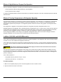
Door bins:
You may put the door bins [52] of the freezer and fresh food compartment in a location that best meets your needs (See Art 00989). To
remove the bins, lift them over the locator and pull them forward. To install the bins, push them onto the locator.
Do not wash the door bins and bin slides in a dishwasher. The door bins and bin slides are not dishwasher safe.
CAUTION
!
NOTICE
NOTICE
NOTICE

Owner’s Manual 5
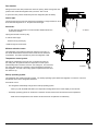
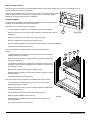
Door bin slide:
Each door bin includes an adjustable door bin slide [53] to prevent the bin contents from moving or overturning during transit (See Art
02632).
Push each door bin slide against the bin contents. To remove each door bin slide, rotate it
out of the bin. Rotate each bin slide into the bin to install.
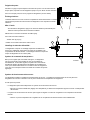
Adjustable shelves:
The shelves in the freezer and the fresh food compartment are made so you can remove
them or move them.
To move or remove the wire shelf of the freezer:
- Locate the plastic clip that is around the wire shelf.
- Remove and save the screw that attaches the plastic clip to the inside of the refrigerator
cabinet.
- Lift the left side of the shelf upward to remove the shelf.
- Push the wire shelf fully into the slot that you wish.
- Put the plastic clip back in the original position on the wire shelf.
- Attach the plastic clip with the screw.
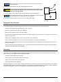
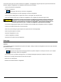
To remove or move the large shelves of the fresh food compartment:
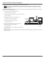
- Locate the plastic clip [202] that is around each wire shelf [203] (See Art
01692).
- Remove and save the screw [41] that attaches the plastic clip to the inside of
the refrigerator cabinet.
- Pull the shelf slightly forward to disengage the left side of the shelf from the
slot [157] of the refrigerator cabinet and lift the left side of the shelf to remove
the shelf.
- Put each wire shelf into the slot that you wish.
- Put the plastic clip back in the original position on each wire shelf.
- Attach the plastic clip with the screw.
To remove the small top shelf of the fresh food compartment:
- Locate the plastic clip [202] that is around the wire shelf [203] (See Art
01692).
- Remove and save the screw [41] that attaches the plastic clip to the inside of
the refrigerator cabinet.
- Pull the shelf forward out of the slot [157].
- Put the wire shelf into the slot.
- Put the plastic clip back in the original position on the wire shelf.
- Attach the plastic clip with the screw.
Art 01692
202
41
157
203
53
52
Art 02632

Owner’s Manual 6
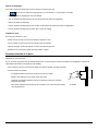
Door handles:
During travel, the door latch prevents the door from opening. When closing each door,
push the door toward the refrigerator until you hear a “click” sound.
To open each door, pull the handle away from the refrigerator (See Art 02633).
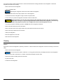
Interior light:
The interior light is at the top of the fresh food compartment. The light remains on at all
times while the refrigerator is on. To replace the interior light:
Shut down:
- To shut down the refrigerator, touch and hold the ON/OFF button two
seconds and release.
Unplug wire harness connector [154].
To remove interior light:
- Remove two (2) screws [41].
Install new light in reverse order.
Moisture reduction heater:
The refrigerator has a heater that prevents moisture from forming on
the center divider between the doors of the freezer and the fresh food
compartment. The heater operates only when the refrigerator is ON.
Temperature control system:
Although the refrigerator is not frost -free, it is made to limit frost on
the cooling ns. At regular intervals, the temperature control system
automatically melts most of the frost from the cooling ns. The water from
the cooling ns drains into a collection cup that is attached to the back of
the refrigerator. The heat of the cooling system evaporates the water from
the collection cup.
Backup operating system:
This refrigerator has a backup operating system. The backup operating system allows the regerator to continue to cool if the
temperature sensor of the refrigerator should fail.
If this failure occurs:
- The refrigerator automatically changes to the backup operating system.
- When you push the TEMP SET button, the temperature setting ashes in the center display for ten seconds.
- The backup operating system can overfreeze or thaw the contents of the freezer and the fresh food compartment.
- Make sure the temperatures of the freezer and the fresh food compartment are satisfactory.
Art 02633
Art 02634
41
154
41
57

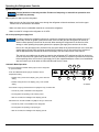
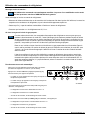
Owner’s Manual 7
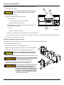
30 31 32
187
277
278
289
AUTO
NORCOLD
MODE
set
CODE
361
Art 02629
Ignition and start up:
Control boards are extremely sensitive. Evidence of tampering or removal from protective case
will VOID any warranty.
Before ignition or start up of the refrigerator:
- Make sure the air ow in the lower intake vent, through the refrigerator coils and condenser, and out the upper
exhaust vent is not blocked or decreased.
- Make sure there are no combustible materials in or around the refrigerator.
- Make sure the DC voltage to the refrigerator is 12.0VDC
Air in the propane gas supply lines
For safety reasons,the refrigerators electronic controls are designed such that while operating in the LP
GAS mode, the trial for ignition (maximum amount of the time the gas valve and igniter can be left on
without a ame present) is limited to 30 seconds. When starting the refrigerator for the rst time, after
storage, or after replacing the propane gas tank, the propane gas supply lines can have air in them.
Due to air in the gas supply lines, the burner may not ignite within the 30 second time limit. In the event this
should happen the gas valve and igniter outputs will be turned off, the LP Gas mode will be “locked out”,
and the appropiate fault code will be shown in the display. See fault code section of this manual.
The gas lock out condition can be reset by powering the refrigerator OFF and then back ON, at which time,
a new 30 second trial for ignition will commence. It may be necessary to repeat this procedure several times
before expelling all the air from the LP gas supply line. If after repeated attempts, a ame is not established,
stop and consult your local dealer or Authorized Norcold Service Center.
Automatic Mode Operation:
- Touch and release the ON/OFF button [30] to turn the refrigerator
on. (See Art 02629).
- Touch the TEMP SET button [32] as needed to set the
temperature setting.
- Number one(1) shown in the display [187] is the warmest
setting.
- Number nine(9) shown in the display [187] is the coldest
setting.
- If the AUTO icon [277] and AC PLUG icon [278] are lit up, it means that:
- 120 volt AC power is available to the refrigerator.
- The refrigerator is operating on AC electric power.
- After ten seconds, the backlight of the display goes off.
- If the AUTO icon and the FLAME icon [289] are lit up, it means that:
- 120 volt AC power is not available to the refrigerator.
- The refrigerator is operating on propane gas.
- After ten seconds, the backlight of the display goes off.
Operating the Refrigerators Controls
NOTICE
NOTICE

Owner’s Manual 8
If neither 120 volts AC nor propane gas are available to the refrigerator :
- 2-way refrigerators:
- The fault codes “no AC” and then “no FL” show in the display and an audible alarm sounds.
- Refer to the “Fault Codes” section of this manual for any faults displayed.
- 3-way refrigerators only:
- The Auto icon and the Battery icon [361] are lit up.
- After ten seconds, the backlight of the display goes off
- This means that the refrigerator is operating on DC electric.
If an energy source is available to the refrigerator but is not operating correctly:
- While operating in the Automatic mode, the refrigerators electronic controls will automatically select the energy source using the
following priority scheme:
1st choice: AC Electric
2nd choice: LP GAS
- When in the Auto mode, if a higher priority choice becomes available (i.e., AC voltage reapplied), the control shall stop
using the current mode and switch to the higher priority mode.
Manual AC Mode Operation:
- Touch and release the ON/OFF button [30] to start the refrigerator
- Touch the MODE button [31] until the AUTO icon goes off and only the AC PLUG icon [278] remains lit.
- Touch the TEMP SET button [32] as needed, to set the temperature setting.
- The AC PLUG icon [278] remains lit until you select a different operating mode or shut down the refrigerator.
Manual LP GAS Operation:
- Touch and release the ON/OFF button [30] to start the refrigerator
- Touch the MODE button [31] until the AUTO icon goes off and only the FLAME icon [289] remains lit.
- Touch the TEMP SET button [32] as needed, to set the temperature setting.
- The FLAME icon [278] remains lit until you select a different operating mode or shut down the refrigerator.
Shut down - All models:
- To shut down the refrigerator, touch and hold the ON/OFF button[30] for two seconds and release.

Owner’s Manual 9
Effects of High Altitude on Propane Gas Operation
When you operate the refrigerator on propane gas at altitudes higher than 5500 feet above sea level:
- You may experience reduced cooling performance of the refrigerator.
- You may experience burner outages.
To avoid these possible problems, Norcold recommends that you operate the refrigerator on AC when at altitudes higher than 5500 feet
above sea level.
Ice Maker (N10LXIM, and NA10LXIM models)
The ice maker is assembled to the refrigerators at the factory as optional equipment. If the refrigerator does not have a factory installed
ice maker, one can not be added to the refrigerator at a later time.
The ice maker is fully automatic and will operate in ambient temperatures as low as 0° F. To allow operation at temperatures between
0° F and 32° F, the ice maker has a heater on the solenoid water valve and on the water line between the solenoid water valve and the
ice maker.
The water line heater does not protect the water supply line from the vehicle shut off valve to the solenoid
water valve on the back of the refrigerator.
When the freezer temperature of the refrigerator is low enough, the ice maker opens the water solenoid valve and lls the mold. The
ice maker ejects the frozen ice into a storage bin. As the storage bin lls, the ice raises the shut-off arm until it turns off the ice maker.
As you use the ice and lower the ice level in the storage bin, the shut-off arm also lowers. This turns the ice maker on and begins the
process of making ice.
The ice maker operates on:
- Cold potable water at a pressure of 15 psi - 125 psi.
- 120 Volts AC (108 VAC min. - 132 VAC max.).
Ice maker operation:
1. Make sure the separate (white) AC power cord which supplies AC to the ice maker is secure.
2. Open the water shut off valve of the vehicle.
Effects of Freezing Temperatures on Refrigerator Operation
A gas absorption refrigerator is not designed to operate in freezing temperatures. If the refrigerator is not equipped for low temperature
operation, and if the cooling system of the refrigerator is exposed to temperatures of 32° F. or lower for an extended period of time,
the refrigerator operation may be disrupted. The refrigerator operation will resume when the cooling system of the refrigerator warms
sufciently.
If the refrigerator is equipped for low temperature operation, the refrigerator will operate in temperatures down to 0° F.
Disrupted operation of the refrigerator, due to extended exposure to temperatures of 32° F. or lower, and any costs incurred to warm the
cooling system of the refrigerator are not covered by the Norcold limited warranty. Please contact your local RV dealer for information
about how to resume refrigerator operation or about how to equip your refrigerator for operation in freezing temperatures.
Do not change the installation or the venting of your refrigerator. Refrigerator failures, which are the result of changes to either the
refrigerator installation or to the venting, are not covered by the Norcold limited warranty.
CAUTION
!

Owner’s Manual 10
Refrigerator Care Checklist
Your refrigerator will give you years of trouble free service if you do these simple checks every three to six months:
- Keep the food compartment and the freezer clean. See “Cleaning”.
- Defrost the refrigerator as necessary. See “Defrosting”.
- Make sure the door seals correctly. See “Door Sealing“.
- Be aware of any cooling changes that are not because of weather, loading, or gas control changes. If changes occur, contact your
dealer or service center.
- Make sure the gas supply is propane gas only and not butane or a butane mixture.
- When in propane gas operation, examine the appearance of the ame. See “Gas Flame Appearance”.
- Make sure the air ow in the lower intake vent, through the refrigerator coils and condenser, and out the upper exhaust vent is not
blocked or decreased.
- Make sure the area behind the refrigerator is clear. Do not use the area behind the refrigerator for storage of anything, especially
gasoline and other ammable vapors and liquids.
Defrosting
The cooling ns of the refrigerator operate at below freezing temperature and will naturally form frost from humidity, which is always
present in the air. The humidity inside the refrigerator increases:
- with higher outside temperature and humidity.
- with the storage of non-sealed fresh foods or warm foods.
- with the amount of time that the door(s) are open.
- with any air leakage into the refrigerator.
Although the refrigerator is not frost -free, it is made to limit frost on the cooling ns. At regular intervals, the temperature control system
automatically melts most of the frost from the cooling ns. The water from the cooling ns drains into a collection cup that is attached to
the back of the refrigerator. The heat of the cooling system evaporates the water from the collection cup.
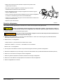
Make sure that the ice maker arm can move freely and does not touch the frozen
foods in the freezer.
3. Push the ice maker arm down to the ON position [50] (See Art 01015).
If you operate the refrigerator without connecting the water supply line and/
or opening the water shut off valve of the vehicle, make sure the ice maker
arm is up in the OFF position.
4. Allow the freezer to cool enough and ice production will begin to ll the storage bin [61].
New plumbing connections and/or impurities in the water supply line after winterizing
can cause the rst ice to be discolored or have an odd avor.
5. To stop the ice maker, push the ice maker arm up to the OFF position [62].
CAUTION
!
NOTICE
NOTICE
Art 01015
60
62
61

Owner’s Manual 11
Cleaning
It is normal for frost to collect inside the freezer. Excess frost decreases the cooling performance of the refrigerator. Defrost the
refrigerator and freezer as necessary:
- Remove all food from the refrigerator.
- Turn the refrigerator OFF.
Defrosting the refrigerator makes excess water inside the refrigerator.
- Remove the drain hose from the drip cup at the rear of the refrigerator.
- Put the drain hose into a half-gallon or larger container to capture water.
- Put dry towels (etc.) inside the refrigerator and freezer to absorb melted frost.
High temperatures can cause the inside surfaces of the refrigerator to warp or melt. Do not use pans of
HOT water, a hair dryer, or any other high temperature devices to defrost the refrigerator. Do not use any
hard or sharp objects to remove frost. Damage to the interior of the refrigerator can occur.
- To increase the speed of defrosting, put pans of WARM water in the refrigerator and freezer.
- Remove the wet towels (etc.) and dry the interior.
- Remove the drain hose from the large container and put the drain hose back into the drip cup.
- Remove the large container from the enclosure.
- Start up the refrigerator.
- Allow the refrigerator to cool down.
- Return all food to the refrigerator.
Interior:
A good time to clean the refrigerator is just after you defrost it. Clean the inside of the refrigerator as often as necessary to avoid food
odors:
- Remove all food from the refrigerator.
Do not use abrasive cleaners, chemicals, or scouring pads because they can damage the interior of the refrigerator.
- Wash the interior with a mild cleaner or a solution of liquid dish detergent and warm water.
- Rinse with a solution of baking soda and clean water.
- Dry with clean cloth.
- Put all food in the refrigerator.
NOTICE
CAUTION
!
NOTICE

Owner’s Manual 12
Drip tray:
To remove and clean the drip tray:
Do not wash the drip tray in a dishwasher. The drip tray is not dishwasher safe.
- Pull the drip tray out of the drain hose.
- Pull the drip tray forward to remove from the slots in the refrigerator cabinet.
- Clean the drip tray.
- Push the drip tray back into the slots in the refrigerator cabinet.
- Push the drip tray back into the drain hose.
Glass shelf:
To clean the glass shelf:
- Remove the screw and grommet that is in front of the glass shelf.
- Pull the glass shelf forward out of the slot
- After cleaning, push the glass shelf fully into the slot.
- Put the screw and grommet back in the orignial position.
Door Sealing
Check the seal of the doors.
If either door does not seal correctly, excess frost will collect inside the refrigerator. Make sure the doors seal correctly (See Art 00980):
- Close each door on a piece of paper that is about the size and thickness of a dollar bill.
- Gently pull the paper.
- You should feel a slight drag between the gasket and the cabinet.
- Do this on all four sides of the door.
- If you do not feel a slight drag on the paper, the door does not seal correctly.
- Have your dealer or an authorized Norcold Service Center correct the seal of the door.
NOTICE
Art 00980

Owner’s Manual 13
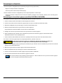
Refrigerator Storage
Before the refrigerator is stored for an extended (seasonal) period of time:
- Defrost and clean the interior of the refrigerator.
- Close the doors with the storage latch.
If the refrigerator is stored for an extended period of time, before start up:
- Make sure there are no obstructions in the vents, the ventilation air pathway, the burner, the orice, or the ue area.
Ice Maker Storage (N10LXIM, and NA10LXIM models)
To prepare the ice maker for seasonal storage:
1. Close the vehicle water supply valve to the ice maker.
2. Push the ice maker arm up until it locks into the OFF position.
3. Remove the garden hose adapter from the water solenoid valve.
4. Remove the ice maker water line from the water solenoid valve
- Do not unwrap the water line heater wires from around the water solenoid valve.
5. Drain all of the water from both the water supply line and the ice maker water line.
6. Put the end of the water supply line, the end of the ice maker water line, and the water solenoid valve each into a clean plastic bag.
7. Use tape to close each plastic bag around the water lines and the water solenoid valve.
To use the ice maker after seasonal storage:
Do not operate the ice maker when the ambient air temperature is 0° F. or lower. Damage to the water
solenoid valve and the water supply line can occur.
1. Remove the tape and plastic bags from the end of the water supply line, the end of the ice maker water line, and the water solenoid
valve.
2. Connect the ice maker water line to the water solenoid valve.
3. Connect the garden hose adapter to the water solenoid valve.
4. Push the ice maker arm down into the ON position.
5. Open the vehicle water supply valve to the ice maker.
You should discard and not use the rst two batches of ice cubes. It will take about three cycles for the ice maker to
make fully formed and clean ice cubes.
CAUTION
!
NOTICE

Owner’s Manual 14
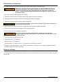
Read and understand the following maintenance sections of this manual.
Norcold is not responsible for installation, adjustment, alteration, service, or maintenance performed by anyone other
than a qualied RV dealer or a Norcold authorized service center.
Have a qualied RV dealer or a Norcold authorized service center do these annual safety and maintenance checks:
- Examine the gas supply lines for leaks.
- Replace or repair if needed.
- Make sure the propane gas pressure is 11 inches of water column.
- Adjust if needed.
- Make sure the combustion seal is complete and intact.
- Replace or repair it if needed.
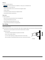
- Make sure the burner and the burner orice are clean.
- Clean if needed.
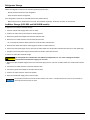
- Make sure the electrode is clean and that the spark gap is 3/16 inch.
(See Art 02673)
- Adjust if needed.
- Make sure the AC voltage is 108 - 132 volts and the DC voltage is
10.5 - 15.4 volts.
- Make sure the area at the rear of the refrigerator is free of any combustible materials, gasoline, and other ammable vapors and
liquids.
Refrigerator Maintenance Checklist
NOTICE
3/16
Art 02673

Owner’s Manual 15
Refrigerator Maintenance
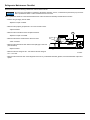
While in GAS operation, examine the appearance of the gas ame:
- Open the lower intake vent.
The burner box door can be hot. Wear gloves to avoid
burns.
- Open viewing door.
- Look at the gas ame [75] (See Art 02684).
- The ame should be:
- A darker blue color on the inside of the ame and a lighter blue
color on the outside of the ame.
- A constant shape without ickering.
- Contact your dealer or Norcold authorized service center if the ame is:
- yellow
- ickering or changing shape.
- Make sure the ame does not touch the inside of the ue tube [76].
- If the ame touches the inside of the ue tube, contact your dealer or Norcold authorized service center.
- Close the burner box door.
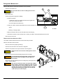
Remove and clean the burner orice:
Your dealer or Norcold authorized service center must do this procedure.
Remove and clean the burner orice:
- Close the valve at the propane gas tank(s).
- Push the ON / OFF button to shut down the refrigerator.
- Open the lower intake vent to expose the back of the refrigerator.
The burner box cover can be hot. Wear gloves to avoid
burns.
- Disconnect the the Gas Train Assembly (GTA) from the LP supply.
To avoid possible propane gas leaks, always use two
wrenches to loosen and tighten the gas supply line
connections.
- Remove the Gas Train Assembly from the cooling unit by removing the two
screws. (See Art 02672)
Do not try to remove the orice from the orice adapter
when cleaning. Removal will damage the orice and seal
of the orice and can cause a propane gas leak. Leaking
propane gas can ignite or explode which can result in
dangerous personal injury or death. Do not clean the
orice with a pin or other objects.
CAUTION
!
Art 02672
WARNING
!
WARNING
!
CAUTION
!
Art 02684
75
76
167

Owner’s Manual 16
Remove the Refrigerator
Your dealer or Norcold authorized service center must do this procedure.
The rear of the refrigerator has sharp edges and corners. To prevent cuts or abrasions when working on the
refrigerator, be careful and wear cut resistant gloves.
1. Close the valve at the propane gas tank(s).
To avoid possible propane gas leaks, always use two wrenches to loosen and tighten the gas supply line
connections.
2. Remove the black AC power cord and the white ice maker AC power cord (N10LXIM and NA10LXIM models only) from the
receptacle.
3. Remove the DC wiring from the refrigerator:
- Put a mark on the DC wires so you can put them back in the correct location.
- Remove the DC fuse or remove the DC wiring from the battery or the converter.
- Remove the DC wires from the refrigerator.
4. Open the lower intake vent and remove the gas supply line from the combination gas valve of the refrigerator.
5. Remove the garden hose adapter from the water solenoid valve (N10LXIM and NA10LXIM models only).
6. Remove the screws from the mounting ange at the rear of the refrigerator.
7. Remove the upper and lower trim pieces from the mounting anges of the refrigerator.
8. Remove the screws from the upper and lower mounting anges on the front of the refrigerator.
9. Remove the refrigerator from the opening.
WARNING
!
CAUTION
!
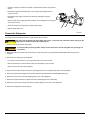
- Clean the openings of the burner tube with compressed air pressure only (See Art
02671)
- Assemble the gas train assembly back to the cooling unit and tighten the two
screws removed.
- Assemble the gas supply to the gas train assembly and tighten using two
wrenches.
- Open the valve at the supply gas tank(s) and turn on the refrigerator choosing gas
as the power source.
- Check all connections for gas leaks using leak test solution.
- Replace lower intake vent.
Air
Air
Air
Air
Art 02671

Owner’s Manual 17
Reinstall the Refrigerator
Your dealer or Norcold authorized service center must do this procedure.
Make sure the combustion seal is not broken, is completely around the refrigerator mounting anges, and
is between the mounting anges and the wall of the enclosure. If the combustion seal is not complete,
exhaust fumes can be present in the living area of the vehicle. The breathing of exhaust fumes can cause
dizziness, nausea, and in extreme cases, death.
1. Push the refrigerator completely into the enclosure.
2. Install the screws in the upper and then the lower mounting anges on the front of the refrigerator.
3. Install the upper and lower trim pieces to the mounting anges of the refrigerator.
4. Install the screws in the mounting ange at the rear of the refrigerator.
To avoid possible propane gas leaks, always use two wrenches to loosen and tighten the gas supply line
connections.
5. Attach the garden hose adapter to the water solenoid valve (N10LXIM and NA10LXIM models only).
6. Attach the gas supply line to the combination gas valve of the refrigerator.
7. Open the valve at the propane gas tank(s).
Do not allow the leak checking solution to touch the electrical components. Many liquids are electrically
conductive and can cause electrical shorts and in some cases, re.
8. Examine the gas supply line for leaks.
9. Connect the DC wiring to the refrigerator:
- Connect the DC wires to the refrigerator.
- Install the DC fuse or connect the DC wiring to the battery or the converter.
10. Connect the black AC power cord and the white ice maker AC power cord (N109XIM and N109XIMXX models only) to the
receptacle.
Replacement Parts
You may purchase replacement parts through your local RV dealer or authorized Norcold Service Center.
WARNING
!
WARNING
!
WARNING
!

Owner’s Manual 18
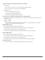
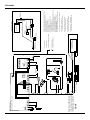
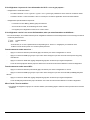
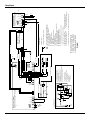
A: Main Control Board/Carte de Commande Principal
B: AC Power Cord/Cordon d'Alimentation CA
C: AC Heater/
Réchauffeur d'AC
*D:
Thermostat/Thermostat
*E: Waterline Heater/Chauffe-Eau
*F: Fan/Ventilateur
G: Divider Heater/Chauffage de Diviseur
H: Ignitor/L'Inflammateur
J: Gas Valve/Distributeur de Gaz
K: Fresh Food Thermistor/Thermistance d'Aliments Frais
L: Interior Light/La lumière de l'intérieur
M: User Interface/L'Interface Utilisateur
*N: DC Heater Board/Carte de Chauffage CC
*P: DC Heater/Chauffe-DC
*R: Cold Weather Heater/Chauffage Par Temps Froid
T1: Spark Transformer/Transformateur d'Allumage
F1, DC-5A Fuse/F1, Fusible 5A DC.............Control Fuse/Le Fusible de Commande
F2, DC-7.5A Fuse/F1, Fusible 7.5A DC.............Auxiliary Fuse/Fusible Auxiliaire
F3, AC-8A Fuse/F3, Fusible 8A AC.........................AC Heater Fuse/Fusible Chauffage AC
*F1, DC-30A Fuse/F1, Fusible 30A DC.....DC Heater Fuse/Fusible Réchauffeur DC
L
H
T
NO
OFF
NC
NO
NC
NO
M
V
N
SW1
SW2
SW3
TF
* Ice Maker/Machine à Glace
MH
TS
WV
MTR
GND
NC
120VAC
120VCA
TF: Thermal Fuse/Fusible Thermique
MH: Mold Heater/Chauffage du Moule
TS: Thermostat/Thermostat
SW1: Shut Off Switch/L'Interrupteur d'Arrêt
MTR: Motor/Motor
SW2: Hold Switch/Commutateur Hold
Sw3: Water Fill Switch/Interrupteur de Remplissage d'Eau
WV: Water Valve/L'Eau de Condensation
Test Points/Des Points de Test
L: Line (120VAC)/Line (120VCA)
H: Molde Heater/Chauffage du Moule
T: Thermostat/Thermostat
N: Neutral/Point Mort
M: Motor/Motor
V: Valve/Distributeur
2
1
2
1
Main Control Board/
Carte de Commande Principal
DNG
NI_TIMIL
TUO_TIMIL
T1
A5.7-2F
F1-5A
F3-8A
P4
TEST
DNG *
CDV21
1
2
3
4
5
P1
User Interface/
L'interface Utilisateur
11 10 9
5
4
38
7
6
2
1
1213141516
2
1
DNG_SISSAHC
DNG_SISSAHC
L1 L2
OL_TH_CA
IH_TH_CA
2_OL_TH_CA
2_IH_TH_CA
P1
GND
GN/VE
BU/BL
BK/NR
WH-VT/BC-VT
CB/HW
WH/BC
GN-YL/VE-JN
CB/HW
GR/DR*
GR/DR
CB-GR/HW-DR
CB-RN/HW-KB
RN-CB/KB-HW
RN/KB*
120VAC
120VCA
A
B
2
1
2
1
*F
H
J
K
OR/OR
M
2
1
*F1-30A
DNG
DNG
CDV21
CDV21
DNG_RTH
RTH_CD
P1
DC Heater Board/
Carte de Chauffage CC
L
*D
*E
G
Auxiliary 12VDC/12VCC Auxiliaire
Auxiliary GND/Gnd Auxiliaire
* : Optional/
En Option
:
Optional/
En Option
: Chassis Ground/La Masse du Châssis
: Test Tool Connection/Branchement de l'outil de Test
TEST
C
*N
*D
*P
*R
BK/NR
BK/NR
NJ/LEY*
NJ/LEY*
GND
CCV21/CDV21
COMM BUS / BUS COMM
12VDC/12VCC
12VDC/12VCC
GND
12VDC/12VCC
GND
GND
12VDC/12VCC
12VDC/12VCC
GND
WH/BC
WH/BC
*COMM BUS / BUS COMM
*D
Side A
Wiring Schematic and Wiring Pictorial
Schéma de câblage et câblage picturale
639064B Model/ Modeles N7/N8/N10
Pictorial

Owner’s Manual 19
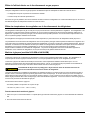
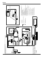
Schematic
Main Control Board/
Carte de Commande Principal
DNG
NI_TIMIL
TUO_TIMIL
T1
A5.7-2F
A5-1F
F3-8A
P4
TEST
CDV21
11 10 9
5
4
38
7
6
2
1
1213141516
2
1
DNG_SISSAHC
DNG_SISSAHC
L1 L2
OL_TH_CA
IH_TH_CA
2_OL_TH_CA
2_IH_TH_CA
P1
A
1
2
3
4
5
P1
User Interface/
L'interface Utilisateur
M
2
1
F1-30A
GND
GND
CDV21
CDV21
HTR_GND
DC_HTR
P1
DC Heater Board/
B
*P
13
P1-11
12
P1-4
P1-2
10
L
K
P1-5
P1-3
*E
*D
8
P1-1
P1-6
4
6
*F
H
J
P1-7
P1-10
*N
* : Optional/
En Option
:
Optional/
En Option
: Chassis Ground/La Masse du Châssis
: Test Tool Connection/
Branchement de l'outil de Test
TEST
A: Main Control Board/Carte de Commande Principal
B: AC Power Cord/Cordon d'Alimentation CA
C: AC Heater/
Réchauffeur d'AC
*D:
Thermostat/Thermostat
*E: Waterline Heater/Chauffe-Eau
*F: Fan/Ventilateur
G: Divider Heater/Chauffage de Diviseur
H: Ignitor/L'Inflammateur
J: Gas Valve/Distributeur de Gaz
K: Fresh Food Thermistor/Thermistance d'Aliments Frais
L: Interior Light/La lumière de L'intérieur
M: User Interface/L'Interface Utilisateur
*N: DC Heater Board/Carte de Chauffage CC
*P: DC Heater/Chauffe-DC
*R: Cold Weather Heater/Chauffage Par Temps Froid
T1: Spark Transformer/Transformateur d'Allumage
F1, DC-5A Fuse/F1, Fusible 5A DC.....
Control Fuse/Le Fusible de Commande
F2, DC-7.5A Fuse/F1, Fusible 7.5A DC.....
Auxiliary Fuse/Fusible Auxiliaire
F3, AC-8A Fuse/F3, Fusible 8A AC.....
AC Heater Fuse/Fusible Chauffage AC
*F1, DC-30A Fuse/F1, Fusible 30A DC.....
DC Heater Fuse/Fusible Réchauffeur DC
C
Green
Green
Brown
Thermal Fuse/
Fusible Thermique
White
White
Black (ribbed)
Black (smooth/bon)
Black
AC Power Cord/
Cordon d'Alimentation CA
Main Control Board/
Carte de Commande Principal
Solenoid
(Water Valve)
+
Ice Maker/
Machine à Glace
* Ice Maker/Machine à Glace
G
Foamed In/En Mousse
*D
*R
P1-13
P1-9
3
P1-12
P1-14
CCV21/CDV21
GND
12VDC/12VCC
GND
*D
Side B
Wiring Schematic and Wiring Pictorial
S
chéma de câblage et câblage pi
cturale
639064B
Model/ Modeles N7/N8/N10

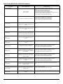
Owner’s Manual 20
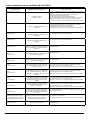
Fault codes Fault Code Meanings Corrective Actions
“no” “FL” Audible alarm.
The burner did not
ignite or re-ignite
Turn the refrigerator power OFF and the back ON to reset.
Check:
- That the valve of the propane gas tank(s) is open.
- That the propane gas is at the correct pressure.
- That the manual shut off valve of the refrigerator is open.
- That there is no air in the propane gas supply line. See “Removing air from
the propane gas supply lines” section of this manual.
- See your dealer or authorized Norcold Service Center.
“no” “AC” Audible alarm also.
AC Voltage is not available to the refrigerator
Check:
- That the refrigerator is plugged into a serviceable outlet.
- That the fuse or circuit breaker or the vehicle is intact.
- That the vehicle generator is operational (if applicable).
- See your dealer or authorized Norcold Service Center.
“AC HE”
with audible alarm
This fault indicates a problem relating to the AC
heater
This is not owner serviceable. See your dealer or authorized Norcold Service
Center.
“dc HE”
with audible alarm
This fault indicates a problem relating to the DC
heater
This is not owner serviceable. See your dealer or authorized Norcold Service
Center.
“dc Er”
with audible alarm
This fault indicates a loss of communication be
-
tween the main Control Board and the DC Board.
This is not serviceable. See your dealer or authorized Norocld Service Center.
“AC rE”
with audible alarm
This fault is within the refrigerator electronic
controls
This is not serviceable. See you dealer or authorized Norcold Service Center.
“dc rE”
with audible alarm
This fault is within the refrigerator electronic
controls
This is not serviceable. See you dealer or authorized Norcold Service Center.
“Lo dc”
without audible alarm
This fault indicates the DC input voltage to the
refrigerator is low. Cooling is to continue.
Check:
- That the battery charging equipment of the vehicle is operational
- That the AC/DC converter is operational (if applicable)
- See your dealer or authorized Norcold Service Center.
“Lo dc”
with audible alarm
This fault indicates the DC input voltage to the
refrigerator is low. Either the LP Gas mode or DC
heater mode (3-way models only), or both have
been inhibited.
Check:
- That the battery charging equipment of the vehicle is operational
- That the AC/DC converter is operational (if applicable)
- See your dealer or authorized Norcold Service Center.
“Lo dC”
with audible alarm
This fault indicates the DC input voltage to the
refrigerator is too low. Either the LP Gas mode or
DC heater mode (3-way models only), or both,
has been inhibited
Check:
- That the battery charging equipment of the vehicle is operational
- That the AC/DC converter is operational (if applicable)
- See your dealer or authorized Norcold Service Center.
“HI dc”
with audible alarm
This fault indicates the DC input voltage to the
refrigerator is too high. All outputs have been
inhibited
Check:
- That the battery charging equipment of the vehicle is operational
- That the AC/DC converter is operational (if applicable)
- See your dealer or authorized Norcold Service Center.
“no dt”
with audible alarm
This fault indicates a loss of communications be
-
tween the controls. The refrigerator will continue
operating in the last “known” operating mode and
temperature setting
Turn the refrigerator OFF and then back ON to reset.
If the fault code continues, see your dealer or authorized Norcold Service
Center
The temperature setting ashes off/on at
one (1) second intervals anytime the user
interface is “awake”.
The thermistor has been sensed inoperable, so
the temperature is being controlled via a backup
operating system
Check:
- That the thermistor is plugged in
- See your dealer or authorized Norcold Service Center
“Sr”
with audible alarm
This fault is within the refrigerator electronic
controls
This is not serviceable. See you dealer or authorized Norcold Service Center.
Fault Codes(All N10LX and NA10LX models)
La page est en cours de chargement...
La page est en cours de chargement...
La page est en cours de chargement...
La page est en cours de chargement...
La page est en cours de chargement...
La page est en cours de chargement...
La page est en cours de chargement...
La page est en cours de chargement...
La page est en cours de chargement...
La page est en cours de chargement...
La page est en cours de chargement...
La page est en cours de chargement...
La page est en cours de chargement...
La page est en cours de chargement...
La page est en cours de chargement...
La page est en cours de chargement...
La page est en cours de chargement...
La page est en cours de chargement...
La page est en cours de chargement...
La page est en cours de chargement...
-
 1
1
-
 2
2
-
 3
3
-
 4
4
-
 5
5
-
 6
6
-
 7
7
-
 8
8
-
 9
9
-
 10
10
-
 11
11
-
 12
12
-
 13
13
-
 14
14
-
 15
15
-
 16
16
-
 17
17
-
 18
18
-
 19
19
-
 20
20
-
 21
21
-
 22
22
-
 23
23
-
 24
24
-
 25
25
-
 26
26
-
 27
27
-
 28
28
-
 29
29
-
 30
30
-
 31
31
-
 32
32
-
 33
33
-
 34
34
-
 35
35
-
 36
36
-
 37
37
-
 38
38
-
 39
39
-
 40
40


Norcold Polar N10LX Le manuel du propriétaire
- Taper
- Le manuel du propriétaire
- Ce manuel convient également à
dans d''autres langues
- English: Norcold Polar N10LX Owner's manual
Documents connexes
-
Norcold N61/N81 Series Le manuel du propriétaire
-
-
-
Norcold N4104/ N4141/ N4150 Le manuel du propriétaire
-
-
-
-
-
 NORCOLD INC Polar N8V/ N8X/ N8LX/ NA8LX Manuel utilisateur
-


