Alienware Area-51 R2 Guide de démarrage rapide
- Taper
- Guide de démarrage rapide

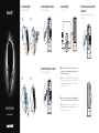
Connect the keyboard and mouse
Connectez le clavier et la souris
Connect the network cable — optional
Connectez le câble réseau (facultatif)
2
3
Connect the display
Connectez l’écran
4
Install the stability foot
Installez le pied de stabilisation
1
1
3
2
4
Connect the power cable and press the
power button
Connectez le câble d’alimentation et appuyez sur le bouton
d’alimentation
5
NOTE: If you have two graphics cards, PCI-Express X16 (graphics) slot 1 will be the
primary graphics card. If you have three graphics cards, PCI-Express X16 (graphics)
slot 3 will be the primary graphics card.
REMARQUE : si vous avez deux cartes graphiques, l’emplacement 1 (carte graphique)
PCI-Express X16 correspondra à la carte graphique principale. Si vous avez trois
cartes graphiques, l’emplacement 3 (carte graphique) PCI-Express X16 correspondra
à la carte graphique principale.
NOTE: Ensure that the input source on the monitor is not set to Auto Select. Select
the input source manually using the On-Screen Display (OSD) menu on the monitor.
REMARQUE : assurez-vous que la source d’entrée du moniteur n’est pas définie sur
Sélection automatique. Sélectionnez la source d’entrée manuellement à l’aide du
menu d’affichage à l’écran sur le moniteur.
Quick Start Guide
Guide d’information rapide
Area-51

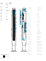
Features
Caractéristiques
3
4
5
6
7
1
2
1. Power button (Alienware logo)
2. Optical-drive eject button
3. Optical drive
4. Headphone port
5. Microphone port
6. USB 3.0 ports (2)
7. Media-card reader
8. Network port
9. Hard-drive activity light
10. USB 2.0 ports (4)
11. USB 3.0 ports (4)
12. Coaxial S/PDIF connector
13. Optical S/PDIF connector
14. Front L/R port
15. Surround L/R port
16. Center/Subwoofer LFE port
17. Rear I/O accessibility lighting button
18. Regulatory label
19. Service Tag label
20. Power connector
21. Power-supply diagnostics button
22. Power-supply diagnostics light
23. Security-cable slot latch
24. Security-cable slot
25. PCI-Express X16 (graphics) slot 1
26. PCI-Express X1 slot
27. PCI-Express X16 (graphics) slot 2
28. PCI-Express X4
29. PCI-Express X16 (graphics) slot 3
1. Bouton d’alimentation (logo Alienware)
2. Bouton d’éjection du lecteur optique
3. Lecteur optique
4. Port écouteurs
5. Port microphone
6. Ports USB 3.0 (2)
7. Lecteur de carte mémoire
8. Port réseau
9. Voyant d’activité du disque dur
10. Ports USB 2.0 (4)
11. Ports USB 3.0 (4)
12. Port S/PDIF coaxial
13. Port S/PDIF optique
14. Port avant gauche/droit
15. Port surround gauche/droit
16. Port LFE caisson de grave/enceinte centrale
17. Bouton arrière d’éclairage d’E/S
18. Étiquette de conformité aux normes
19. Étiquette de numéro de série
20. Port d’alimentation
21. Bouton de diagnostics d’alimentation
22. Voyant de diagnostics d’alimentation
23. Loquet de l’emplacement pour câble de sécurité
24. Emplacement pour câble de sécurité
25. Emplacement 1 (carte graphique) PCI-Express X16
26. Emplacement PCI-Express X1
27. Emplacement 2 (carte graphique) PCI-Express X16
28. PCI-Express X4
29. Emplacement 3 (carte graphique) PCI-Express X16
Product support and manuals
Support produits et manuels
alienware.com
dell.com/support/manuals
Contact Dell
Contacter Dell
dell.com/contactdell
Regulatory and safety
Réglementations et sécurité
dell.com/regulatory_compliance
Regulatory model
Modèle réglementaire
D03X
Regulatory type
Type réglementaire
D03X001
Computer model
Modèle de l’ordinateur
Alienware Area-51 R2
2015-01© 2014–2015 Dell Inc.
Printed in China.
20
21
26
17
23
18
19
24
22
25
27
28
29
8
9
10
11
12
13
14
15
16
-
 1
1
-
 2
2


Alienware Area-51 R2 Guide de démarrage rapide
- Taper
- Guide de démarrage rapide
Documents connexes
Autres documents
-
MSI MS-7640 G52-76401X3 Le manuel du propriétaire
-
 Sapphire Audio PC-AM2RD790 Manuel utilisateur
-
MSI Z68S-G43 (G3) Le manuel du propriétaire
-
-
MSI MS-7881v2.0 Le manuel du propriétaire
-
-
MSI X99S SLI Krait Edition Le manuel du propriétaire
-
-
