Klein Tools VDV512-101 Mode d'emploi
- Catégorie
- Testeurs de réseau câblé
- Taper
- Mode d'emploi

GENERAL SPECIFICATIONS
The Klein Tools Coax Explorer
®
2 verifies proper continuity of F-connector coaxial cables
and maps their location. The color-coded push-on remotes allow for up to four cables
to be tested and mapped, displaying cable status via LED indicators (PASS, OPEN, or
SHORT) that also identify the cable/remote location.
• Environment: Indoor
• Operating Altitude: 10000 ft. (3000 m) maximum
• Operating Temperature: 32° to 122°F (0° to 50°C)
• Storage Temp: -4° to 140°F (-20° to 60°C)
• Relative Humidity: 10% to 90% non-condensing
• Dimensions (including remote holder): 5.7" x 2.3" x 1.1" (145 x 32 x 29 mm)
• Weight (including batteries): 4.8 oz. (136 g)
Specifications subject to change.
TESTING/MAPPING CABLES
NOTE: Not for use on powered circuits or outlets.
1. Connect a test remote
1
,
2
,
3
or
4
to one end of the cable or outlet to be
tested. If necessary, use the included F-adapter
9
to connect the test remote to
the cable. If mapping, install remaining remotes to additional locations.
2. Connect the opposite end of the cable or outlet to be tested to the F-connector
5
on the Coax Explorer
®
2.
3. Press and hold the TEST button
10
. If the cable is wired correctly, one of the four
PASS LEDs
11
will light, also indicating the cable/remote location. If there is a
problem with the cable, one of the FAULT LEDs (OPEN
12
or SHORT
13
) will light.
4. Repeat steps 2 and 3 to test/map additional cables.
TESTING AN UNINSTALLED CABLE
1. Using the included F-adapter
9
, connect a test remote
1
to one end of the cable
to be tested.
2. Connect the opposite end of the cable to be tested to the F-connector
5
on the
Coax Explorer
®
2.
3. Press and hold the TEST button
10
. If the cable is wired correctly, the
corresponding PASS LED
11
will light. If there is a problem with the cable, one of
the FAULT LEDs (OPEN
12
or SHORT
13
) will light.
REMOTE HOLDER/STORAGE
The test remotes conveniently snap into the remote holder
8
for storage. To store the
included F-adapter
9
, push two remotes onto the adapter before snapping the remotes
into the holder.
The remote holder snaps onto the body of the Coax Explorer
®
2 and may be removed if
desired. Hold the tester in one hand and apply slight downward pressure to one side of
the remote holder with the other hand to release it from the tester. To reattach, align the
holder with the tester body and snap back into place.
BATTERY REPLACEMENT (FIG. 1)
When the TEST button is pressed and no LEDs light, the batteries must be replaced.
1. Unscrew the battery cap
6
.
2. Remove and recycle the two spent AAA batteries
7
.
3.
Install two new AAA batteries, with the positive (+) side facing into the tester as shown.
4. Screw battery cap tightly back into place.
STORAGE
Remove the batteries when the tester is not in use for a prolonged period of time. Do not
expose to high temperatures or humidity. After a period of storage in extreme conditions
exceeding the limits mentioned in the GENERAL SPECIFICATIONS section, allow the tester
to return to normal operating conditions before using.
WARRANTY
www.kleintools.com/warranty
DISPOSAL / RECYCLE
Do not place equipment and its accessories in the trash. Items must be
properly disposed of in accordance with local regulations. Please see
www.epa.gov or www.erecycle.org for additional information.
CUSTOMER SERVICE
KLEIN TOOLS, INC.
450 Bond Street, Lincolnshire, IL 60069 1-877-775-5346
[email protected] www.kleintools.com
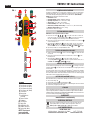
FIG. 1
5
8
1 3
10
12
13
11
4
9
2
14
7
6
ENGLISH
ENGLISH
1.
Test Remote #1 (Red)
2.
Test Remote #2 (Blue)
3.
Test Remote #3 (Green)
4.
Test Remote #4 (Black)
5.
F-Connector
6.
Battery Cap
7.
2x AAA Batteries
(included)
8.
Remote Holder
9.
F-Adapter
10.
TEST Button
11.
PASS LEDs
12.
OPEN Fault LED
13.
SHORT Fault LED
14.
Pocket Clip (Back)
NOTE: There are no
user-serviceable
parts inside tester.
VDV512-101 Instructions

ESPECIFICACIONES GENERALES
El probador Coax Explorer
®
2 de Klein Tools verifica la continuidad apropiada de los cables
coaxiales con conectores F y mapea su ubicación. Los transmisores remotos a presión
codificados por color permiten probar y mapear hasta cuatro cables, y los indicadores LED
(PASS ["PRUEBA APROBADA"] OPEN ["CIRCUITO ABIERTO"] o SHORT ["CORTOCIRCUITO"])
muestran el estado de loscables e identifican la ubicación del cable/transmisor remoto.
• Entorno: Interior
• Altitud de funcionamiento: 10000pies (3000 m) como máximo
• Temperatura de operación: 32°F a 122°F (0°C a 50°C)
• Temperatura de almacenamiento: -4°F a 140°F (-20°C a 60°C)
• Humedad relativa: 10% a 90%, sin condensación
• Dimensiones (incluido el portatransmisor): 5,7" × 2,3" × 1,1" (145mm × 32mm × 29mm)
• Peso (incluidas las baterías): 4,8 oz (136 g)
Especificaciones sujetas a cambios.
PRUEBA Y MAPEO DE CABLES
NOTA: No utilizar en circuitos o tomacorrientes con energía.
1. Conecte un transmisor remoto de prueba
1
,
2
,
3
o
4
a un extremo del cable o al
tomacorriente que desee probar. Si es necesario, utilice el adaptador F
9
provisto para
conectar el transmisor remoto de prueba al cable. En caso de que realice un mapeo, instale
los transmisores remotos restantes en ubicaciones adicionales.
2. Conecte el otro extremo del cable o el tomacorriente que desee probar al conector F
5
en
el probador Coax Explorer
®
2.
3.
Mantenga presionado el botón TEST ("PROBAR")
10
. Si el cable está correctamente cableado,
se encenderá uno de los cuatro LED PASS ("PRUEBA APROBADA")
11
, que también indicará la
ubicación del cable/transmisor remoto. Si hay un problema en el cable, se encenderá uno delos
LED FAULT ("FALLA") (OPEN ["CIRCUITO ABIERTO"]
12
o SHORT ["CORTOCIRCUITO"]
13
).
4. Repita los pasos 2 y 3 para probar/mapear otros cables.
PRUEBA DE UN CABLE NO INSTALADO
1. Utilice el adaptador F
9
, provisto para conectar el transmisor remoto de prueba
1
a un
extremo del cable que desee probar.
2. Conecte el otro extremo del cable que desee probar al conector F
5
en el probador
coaxialExplorer
®
2.
3. Mantenga presionado el botón TEST ("PROBAR")
10
. Si el cable está correctamente
cableado, se encenderá el LED PASS ("PRUEBA APROBADA")
11
. Si hay un problema con
el cable, se encenderá uno de los LED FAULT ("FALLA") (OPEN [CIRCUITO ABIERTO]
12
o
SHORT [CORTOCIRCUITO]
13
).
PORTATRANSMISOR REMOTO/ALMACENAMIENTO
Los transmisores remotos de prueba calzan a presión cómodamente en el portatransmisor
remoto
8
para su almacenamiento. Para guardar el adaptador F provisto
9
, presione dos
transmisores remotos hacia el interior del adaptador antes de calzar los transmisores remotos
en el portatransmisor.
El portatransmisor remoto calza en el cuerpo del probador Coax Explorer
®
2 y se puede extraer,
si se desea. Sostenga el probador con una mano y, con la otra mano, presione levemente uno
de los costados del portatransmisor remoto hacia abajo para liberarlo del probador. Para volver
a calzarlo, alinee el portatransmisor con el cuerpo del probador y cálcelonuevamente en su
lugar.
REEMPLAZO DE LAS BATERÍAS (FIG. 1)
Las baterías deben reemplazarse si no se enciende ningún LED al presionar el botón TEST ("PROBAR").
1. Desenrosque la tapa del compartimento de baterías
6
.
2. Retire y recicle las dos baterías AAA agotadas
7
.
3. Instale dos baterías AAA nuevas con el lado positivo (+) orientado hacia el probador,
comose muestra.
4. Enrosque la tapa del compartimento de baterías firmemente en su lugar.
ALMACENAMIENTO
Retire las baterías si no va a utilizar el probador durante un tiempo prolongado. No lo exponga
a la humedad ni a altas temperaturas. Luego de un período de almacenamiento en condiciones
extremas que sobrepasen los límites mencionados en la sección ESPECIFICACIONES GENERALES,
deje que el probador vuelva a las condiciones de funcionamiento normales antes de utilizarlo.
GARANTÍA
www.kleintools.com/warranty
ELIMINACIÓN/RECICLAJE
No arroje el equipo ni sus accesorios a la basura. Los elementos se deben
desechar correctamente de acuerdo con las regulaciones locales. Para obtener
másinformación, consulte www.epa.gov o www.erecycle.org.
SERVICIO AL CLIENTE
KLEIN TOOLS, INC.
450 Bond Street, Lincolnshire, IL 60069 1-877-775-5346
[email protected] www.kleintools.com
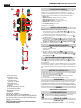
FIG. 1
5
8
1 3
10
12
13
11
4
9
2
14
7
6
1. Transmisor remoto
de prueba n.º1 (rojo)
2. Transmisor remoto
de prueba n.º2 (azul)
3. Transmisor remoto
de prueba n.º3 (verde)
4. Transmisor remoto
de prueba n.º4 (negro)
5.
Conector F
6.
Tapa del compartimento de baterías
7.
2baterías AAA (incluidas)
8.
Portatransmisor remoto
9.
Adaptador F
10.
Botón TEST ("PROBAR")
11.
LED que indica PASS ("PRUEBAAPROBADA")
12.
LED FAULT ("FALLA") que indica OPEN ("CIRCUITO ABIERTO")
13.
LED FAULT ("FALLA") que indica SHORT ("CORTOCIRCUITO")
14.
Clip de bolsillo (espalda)
NOTA: El probador no contiene en su interior piezas que
el usuario puedareparar.
ESPAÑOL
VDV512-101 Instrucciones

CARACTÉRISTIQUES GÉNÉRALES
Le CoaxExplorer
®
2 de KleinTools vérifie la continuité des câbles coaxiaux à connecteur enF
et mappe leur emplacement. Les capteurs à distance chromocodés à enfiler permettent de
tester et de mapper jusqu’à 4câbles en indiquant l’état de chacun d’eux par des voyantsDEL
(«PASS» [test réussi], «OPEN» [circuit ouvert] ou «SHORT» [court-circuit]), qui précisent
aussi l’emplacement du câble et du capteur à distance.
• Environnement: À l’intérieur
• Altitude de fonctionnement: 3000m (10000pi) maximum
• Température de fonctionnement: 0°C à 50°C (32°F à 122°F)
• Température d’entreposage: -20°C à 60°C (-4°F à 140°F)
• Humidité relative: 10 à 90%, sans condensation
• Dimensions (incluant le support pour capteurs à distance): 145x 32x 29mm
(5,7x 2,3x 1,1po)
• Poids (avec les piles): 136g (4,8oz)
Les caractéristiques techniques peuvent faire l’objet de modifications.
TEST ET MAPPAGE DES CÂBLES
REMARQUE: Évitez l’utilisation sur des prises et des circuits alimentés.
1. Connectez le capteur de test à distance
1
,
2
,
3
ou
4
à une extrémité du câble ou
de la prise à tester. Au besoin, utilisez l’adaptateur de connecteur enF
9
inclus pour
connecter le capteur de test à distance au câble. Lors du mappage, répartissez les autres
capteurs de test à distance entre divers emplacements.
2. Connectez l’extrémité opposée du câble ou de la prise à tester au connecteur enF
5
sur
le Coax Explorer
®
2.
3. Appuyez sur le bouton «TEST»
10
et maintenez-le enfoncé. Si le câblage est correct, un
des 4voyantsDEL «PASS» (test réussi)
11
s’allumera et indiquera aussi l’emplacement
du câble et ducapteur à distance. Si un problème survient avec le câble, un des voyantsDEL
FAULT (anomalie) («OPEN» [circuit ouvert]
12
ou «SHORT» [court-circuit]
13
) s’allumera.
4. Répétez les étapes2 et 3 pour tester ou mapper d’autres câbles.
TEST D’UN CÂBLE NON INSTALLÉ
1. À l’aide de l’adaptateur de connecteur enF
9
compris, connectez le capteur de test à
distance
1
à une extrémité du câble à tester.
2. Connectez l’extrémité opposée du câble à tester au connecteur enF
5
sur le
CoaxExplorer
®
2.
3. Appuyez sur le bouton «TEST»
10
. et maintenez-le enfoncé. Si le câblage est correct, le
voyantDEL «PASS»
11
(test réussi) correspondant s’allumera. Si un problème survient
avec le câble, un des voyantsDEL FAULT (anomalie) («OPEN»
12
[circuit ouvert] ou
«SHORT»
13
[court-circuit]) s’allumera.
SUPPORT POUR TENIR ET ENTREPOSER LES CAPTEURS À DISTANCE
Les capteurs de test à distance se placent facilement sur le support
8
pour être entreposés.
Pour entreposer l’adaptateur de connecteur enF inclus
9
, placez deux capteurs à distance
surl’adaptateur avant de les fixer sur le support.
Le support pour capteurs à distance se fixe au boîtier du CoaxExplorer
®
2 et peut être retiré
au besoin. Tenez le testeur dans une main et, de l’autre, appuyez doucement vers le bas sur un
côté du support afin de le détacher du testeur. Pour le fixer à nouveau, alignez le support avec
leboîtier du testeur, puis appuyez.
REMPLACEMENT DES PILES (FIG. 1)
Lorsque vous enfoncez le bouton «TEST» et qu’aucun voyantDEL ne s’allume, remplacez
lespiles.
1. Dévissez le couvercle du compartiment à piles
6
.
2. Retirez et recyclez les deux pilesAAA à plat
7
.
3. Placez deux nouvelles pilesAAA dans le testeur, côté positif (+) vers le haut, comme illustré.
4. Replacez le couvercle du compartiment à piles en le vissant bien serré.
ENTREPOSAGE
Retirez les piles lorsque vous ne prévoyez pas utiliser le testeur pendant une longue période.
N’exposez pas l’appareil à des températures ou à un taux d’humidité élevés. Après une période
de stockage dans des conditions extrêmes (hors des limites mentionnées dans la section
CARACTÉRISTIQUES GÉNÉRALES), laissez le testeur revenir à des conditions d’utilisation
normales avant de l’utiliser.
GARANTIE
www.kleintools.com/warranty
MISE AU REBUT/RECYCLAGE
Ne mettez pas l’appareil et ses accessoires au rebut. Ces articles doivent
être éliminés conformément aux règlements locaux. Pour de plus amples
renseignements, consultez les sites www.epa.gov ou www.erecycle.org.
SERVICE À LA CLIENTÈLE
KLEIN TOOLS, INC.
450 Bond Street, Lincolnshire, IL 60069 1-877-775-5346
[email protected] www.kleintools.com
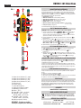
1.
Capteur de test à distance n
o
1 (rouge)
2.
Capteur de test à distance n
o
2 (bleu)
3.
Capteur de test à distance n
o
3 (vert)
4.
Capteur de test à distance n
o
4 (noir)
5.
Connecteur enF
6.
Couvercle de piles
7.
2pilesAAA (comprises)
8.
Support pour capteurs à distance
9.
Adaptateur de connecteur enF
10.
Bouton «TEST»
11.
VoyantsDEL «PASS» (test réussi)
12.
VoyantDEL «FAULT» (anomalie)
indiquant «OPEN» (circuit ouvert)
13.
VoyantDEL «FAULT» (anomalie)
indiquant «SHORT» (court-circuit)
14.
Agrafe pour poche (à l’arrière)
REMARQUE: Ce testeur ne contient
aucune pièce réparable par l’utilisateur.
FIG. 1
5
8
1 3
10
12
13
11
4
9
2
14
7
6
FRANÇAIS
VDV512-101 Directives
-
 1
1
-
 2
2
-
 3
3


Klein Tools VDV512-101 Mode d'emploi
- Catégorie
- Testeurs de réseau câblé
- Taper
- Mode d'emploi
dans d''autres langues
Documents connexes
-
Klein Tools VDV512-110 Mode d'emploi
-
-
Klein Tools VDV770-850 Manuel utilisateur
-
Klein Tools VDV770-850 Mode d'emploi
-
-
Klein Tools VDV501-826 Mode d'emploi
-
-
-
Klein Tools VDV501-826 Manuel utilisateur
-