United States Stove 2016EB Le manuel du propriétaire
- Catégorie
- Cheminées
- Taper
- Le manuel du propriétaire

852531F-0404i
United States Stove Company
227 Industrial Park Road
P.O. Box 151
South Pittsburg, TN 37380
Owner’s Operation and Instruction Manual
SAFETY NOTICE:
If this heater is not properly installed, a house re
may result. For your safety, follow the installation
instructions. Never use make-shift compromises
during the installation of this heater. Contact local
building or re ofcials about permits, restrictions
and installation requirements in your area.
CAUTION!
Please read this entire manual before you install
or use your new room heater. Failure to follow
instructions may result in property damage, bodily
injury, or even death. Improper Installation Could
Void Your Warranty!
SAVE THESE INSTRUCTIONS
THIS MANUAL WILL HELP YOU TO OBTAIN EFFICIENT, DEPENDABLE SERVICE FROM THE HEATER, AND ENABLE YOU
TO ORDER REPAIR PARTS CORRECTLY. KEEP IN A SAFE PLACE FOR FUTURE REFERENCE.
MODELS: 2016E(B)
PEDESTAL PLATE HEATER
Report #: 0215WS045E, 0215WS045S
Certied to: UL 1482-11 (R2015) and Certied to:
ULC-S627-00 and ASTM 2780/Method 28R
Do not use this heater in a Mobile home or trailer!
U.S. Environmental Protection Agency
Certied to comply with 2015 particulate emission
standards for single burn rate heaters. Not approved
for sale after May 15, 2020. This single burn rate wood
heater is not approved for use with a ue damper.
CALIFORNIA PROPOSITION 65 WARNING:
This product can expose you to chemicals including carbon monoxide, which
is known to the State of California to cause cancer, birth defects and/or other
reproductive harm. For more information, go to www.P65warnings.ca.gov
Ce produit peut vous exposer à des produits chimiques, y compris le
monoxyde de carbone, qui est connu dans l'État de Californie pour causer
le cancer, des malformations congénitales et / ou d'autres problèmes de
reproduction. Pour plus d'informations, visitez www.P65warnings.ca.gov

2
SAFETY NOTICE: If this heater is not properly installed a house re may result. Do not use make-shift compromises
during installation. Clean your stove frequently to reduce soot, creosote and ash accumulation. For your safety,
follow the installation directions. Contact local building or re ofcials about restrictions, permits and installation
inspection requirements in your area. The room heater must be connected to a chimney complying with the
requirements for Type HT chimneys in the Standard for Chimneys, Factory-Built, Residential Type and Building
Heating Appliance, UL 103, or a code approved masonry chimney with a ue liner. Please read this entire
manual before you install and use you new room heater. Failure to follow instructions may result in property
damage, bodily injury, or even death.
Read these rules and the instructions carefully
1. Check with local codes. The installation comply
with their rulings. Observe closely the clearances
to combustibles specied in this manual.
2. Do not install this heater in a mobile home or trailer.
3. DO NOT connect a wood burning heater to
an aluminum Type B gas vent. This is not safe
and is prohibited by the National Fire Protection
Association Code.
4. Always connect this heater to a chimney and
vent to the outside. Never vent to another room or
inside a building.
5. The freestanding room heater requires a masonry
or a UL Listed Residential Type and Building Heating
Appliance Chimney.
6. Be sure that your chimney is safely constructed and
in good repair. Have the chimney inspected by
the Fire Department or a qualied inspector. Your
insurance company may be able to recommend
a qualied inspector.
7. Make sure the chimney is high enough to give a
good draft.
8. Inspect chimney connector and chimney twice
monthly during the heating season for any deposit
of creosote or soot which must be removed (see
Chimney Maintenance).
9. DO NOT BE ALARMED IF HEATER SMOKES UPON
INITIAL FIRING. The special paint used on this heater
must be cured during initial ring. This smoking will
occur only on initial ring.
10. CAST IRON PARTS MUST BE "SEASONED" TO AVOID
CRACKING. BUILD ONLY SMALL FIRES DURING THE
FIRST FEW DAYS OF USE.
11. To prevent injury, do not allow anyone to use this
heater who is unfamiliar with the correct operation
of the heater.
12. For additional information on using your Room
Heater safely, obtain a copy of the National
Fire Protection Association (NFPA) publication
"Chimneys, Fireplaces, and Solid Fuel Burning
Appliances" NFPA No. 211(USA).
13. Disposal of Ashes- Place ashes in a metal container
with a tight tting lid. Keep the closed container
on a non-combustible oor or on the ground, well
away from all combustible materials. Keep the
ashes in the closed container until all cinders have
thoroughly cooled. The ashes may be buried in the
ground or picked up by a refuse collector. Never
use the ash container to dispose of other waste.
14. Keep the rebox section free of excess ashes.
15. Observe clearances to combustible materials
specied in this manual to avoid a re hazard.
16. CARING FOR PAINTED PARTS- This heater has a
painted jacket, which is durable but it will not
stand rough handling or abuse. When installing
your heater, use care in handling. Clean with soap
and warm water when heater is not hot. DO NOT
use any acids or scouring soap, as these wear and
dull the nish. PAINT DISCOLORATION WILL OCCUR
IF THE HEATER IS OVERFIRED. FOLLOW OPERATING
INSTRUCTIONS CAREFULLY.
17. The rebox walls in this heater may become slightly
distorted over a period of use. The slight distortion
does not affect the operation of the unit.
18. CAUTION: HOT WHILE IN OPERATION. KEEP
CHILDREN, CLOTHING, AND FURNITURE AWAY.
CONTACT MAY CAUSE SKIN BURNS.
19. DO NOT USE CHEMICALS OR FLUIDS TO START THE
FIRE.
20. DO NOT BURN GARBAGE OR FLAMMABLE FLUIDS
SUCH AS GASOLINE, NAPHTHA OR ENGINE OIL.
21. CAUTION: DO NOT CONNECT TO OR USE IN
CONJUNCTION WITH ANY AIR DISTRIBUTION
DUCTWORK UNLESS Specically APPROVED FOR
SUCH INSTALLATIONS.
22. CAUTION: STORE SOLID WOOD FUEL A SAFE
DISTANCE AWAY. DO NOT STORE SOLID WOOD
FUEL WITHIN HEATER INSTALLATION CLEARANCES OR
WITHIN THE SPACE REQUIRED FOR ASH REMOVAL.
23. DO NOT USE A GRATE OR ELEVATE THE FIRE - BUILD
FIRE DIRECTLY ON HEARTH.
24. WE RECOMMEND THAT SMOKE DETECTORS BE
INSTALLED IN YOUR HOME. Smoke from this
appliance may activate the smoke detector if
door is open.
25. An adequate supply of combustion air must be
provided into the room where the unit is installed.
26. Do Not Overre - if heater or chimney glows, you
are overring
CAUTION: Do not touch the metal or glass surfaces of the heater until it has thoroughly cooled.
Safety Rules

3
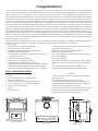
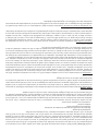
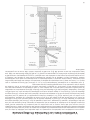
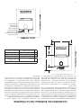
(SIDE VIEW)
(FRONT VIEW)
(TOP VIEW)
Congratulations!
You've purchased a heater from North America's oldest manufacturer of wood burning products. By heating
with wood you're helping to CONSERVE ENERGY! Wood is our only Renewable Energy Resource. Please do your
part to preserve our wood supply. Plant at least one tree each year. Future generations will thank you. This
manual describes the installation and operation of the United States Stove Company Model 2016EB woodheater.
This heater meets the 2015 U.S. Environmental Protection Agency's crib wood emission limits for woodheaters sold
after May 15, 2015. Under specic EPA test conditions burning Douglas Fir dimensional lumber this heater has been
shown to deliver heat at a rate of 35,750 Btu/hr. This heater achieved a particulate emissions rate of 3.7 g/hr when
tested to method ASTM E2780-10 single Burn Rate Appendix (*and an efciency of 66.6%.) This wood heater has
a manufacturer-set minimum low burn rate that must not be altered. It is against federal regulations to alter this
setting or otherwise operate this wood heater in a manner inconsistent with operating instructions in this manual.
The operation of this wood heater in a manner inconsistent with the owner’s manual will void you warranty and is
also against federal regulations. This heater is designed to burn natural wood only. Higher efciencies and lower
emissions generally result when burning air dried seasoned hardwoods, as compared to softwoods or to green
or freshly cut hardwoods. Burning the following materials may result in release of toxic fumes or render the heater
ineffective and cause smoke.
This wood heater needs periodic inspection and repair for proper operation. It is against federal regulations to
operate this wood heater in a manner inconsistent with operating instructions in this manual.
DO NOT BURN:
• Residential or commercial garbage;
• Lawn clippings or yard waste;
• Materials containing rubber, including tires;
• Materials containing plastic;
• Waste petroleum products, paints or paint thinners,
or asphalt products;
• Materials containing asbestos;
• Construction or demolition debris;
• Paper products, cardboard, plywood, or
particleboard. The prohibition against burning these
materials does not prohibit the use of re starters
made from paper, cardboard, saw dust, wax and
similar substances for the purpose of starting a re in
unaffected wood heater.
• Railroad ties or pressure-treated wood;
• Manure or animal remains;
• Salt water driftwood or other previously salt water
saturated materials;
• Unseasoned wood;
• Any materials that are not included in the warranty
and owner’s manual for the subject wood heater;
or
• Any materials that were not included in the
certication tests for the subject wood heater.
TOOLS AND MATERIALS NEEDED
TOOLS
• Pencil
• 6 Foot Folding Rule or Tape Measure
• Drill, Hand or Electric
• Drill Bit 1/8" Dia. (For Sheet Metal Screws)
• 5/16" Nut Driver or 5/16" Socket w/Ratchet
• Screw Driver (Blade-Type)
• Gloves
• Safety Glasses
MATERIALS
• 6" Pipe, 6" Elbow, Collar and Thimble; As Required
(24 gauge min.)
• 1/2" Sheet Metal Screws (No. 10A x 1/2")
• 6" Inside Diameter Underwriters Laboratories (UL)
Listed Residential Solid Fuel Factory-Built Triple wall
Chimney or Exiting Masonry Chimney.
• Floor Protector Material As Specied in this manual.
• Furnace Cement (Manufacturer Recommends:
Rutland Black Code 78 or Equivalent)

4
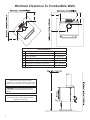
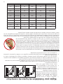
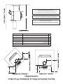
Minimum Clearance To Combustible Walls
D
E
D
E
A
F
B
G
C
D
E
D
E
A
F
B
G
C
D
E
D
E
A
F
B
G
C
Minimum clearances for corner
installation is 12 inches (305mm) from the
corners of the heater to the nearest wall.
The provision that clearances may only
be reduced by means approved by
regulatory authority
CAUTION: Keep furnishings and other
combustible materials away from the
heater.
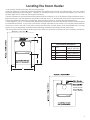
Stove Clearances
A Side Wall 18" (457mm)
B Back Wall 12" (305mm)
C Ceiling Height 84" (2134mm)
D Closest Wall to Corner 12" (305mm)
E Wall to Chimney Connector (Alcove) 21" (533.4mm)
F Side Wall to Chimney Connector 22.25" (565mm)
G Back Wall to Chimney Connector 15" (381mm)

5
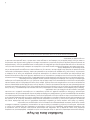
As A Location Is Selected, Keep The Following In Mind
Keep the chimney connection as short as possible. The heater must have its own chimney ue. Do not connect
any other appliance to the same ue. If there is no chimney where you wish to place the heater, you can use a
UL Listed Type 103 HT, Solid Fuel, Factory Built Chimney.
Place the heater on a manufactured oor protector that conforms to UL 1618, that provides at minimum type 1
ember protection. The oor protector should be under the stove, 16” beyond the front and 8” beyond each side
of the fuel loading and ash removal opening. Have the oor protector with the specied dimensions.
Check Figures 2, 3, & 4. You should have at least the clearances shown from the heater and the connector pipe
to combustible surfaces. If you have a solid brick or stone wall behind your heater, you can place the heater as
close as you wish to the wall. If the wall is only faced with brick or stone, treat it as a combustible wall. You may
consult your local regulatory authority before reducing clearances specied in these instructions.
The oor protector must extend under the product and two (2) inches on either side of the chimney connector.
Locating The Room Heater
L
K
J
H
I I
exits the back your
must extend 2”
(51mm) on both
L
K
J
H
I I
exits the back your
must extend 2”
(51mm) on both
Floor Protector Clearances
H Front
US 16" (406mm)/
CAN 18" (457mm)
I Side 8" (203mm)
J Rear CAN 8" (203mm)
K Overall width 38-5/8" (981mm)
L Overall Depth 45-5/16" (1.15m)

6
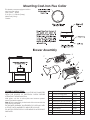
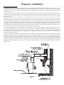
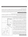
This heater comes equipped with a
cast-iron ue collar.
Flue Collar - 40292
5/16-18 x 1-1/2" Bolts (3 req.)
Weld Tab (3 req.)
Gasket
Mounting Cast-Iron Flue Collar
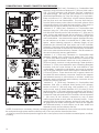
KEY DESCRIPTION PART NO. QTY.
1 Blower Housing Back 25089B 1
2 Blower Housing Front 25090B 1
3 Blower Motor 80442 1
4 Rheostat w/Nut and Knob 80090 1
5 Strain Relief Bushing 80109 1
6 Power Supply Cord 80232 1
7 Heat Shield 891861 1
8 10AB x 3/8 Hex Screw 83172 12
N/S #12 x 3/4 Teks Screw C23799 4
ASSEMBLY INSTRUCTIONS
Step 1: THE BLOWER ASSEMBLY MUST BE DISCONNECTED
FROM THE SOURCE OF ELECTRICAL SUPPLY BEFORE
ATTEMPTING THE INSTALLATION.
With pliers, cut the 6 micro-joints and remove panel.
Note: Discard the panel.
Step 2: Fix the assembly to the back of the stove with the
four screws provided.
THE BLOWER ASSEMBLY IS INTENDED FOR USE ONLY WITH
A STOVE THAT IS MARKED TO INDICATE SUCH USE.
DO NOT ROUTE THE SUPPLY CORD NEAR OR ACROSS HOT
SURFACES!
Blower Assembly
1
2
3
4
5
6
7
8

7
CHIMNEY CONNECTION
Take into account the chimney’s location to insure it is not
too close to neighbours or in a valley which may cause
unhealthy or nuisance conditions. Your chimney connector
and chimney must have the same diameter as the stove
outlet (6”). If this is not the case, we recommend you contact
your dealer in order to insure there will be no problem with
the draft .
The stove pipe must be made of aluminized or cold roll steel
with a minimum thickness of 0.021” or 0.53mm. It is strictly
forbidden to use galvanized steel.
Two basic types of chimneys are approved for use with solid
fuel. Factory-built and masonry. Factory-built chimney must
comply with UL standard in the US and ULC standards for
Canada.
Do not expect your stove or furnace to create draft. Draft is
not a function of the appliance. Draft is purely a function of
the chimney. Modern stoves and furnaces are much more
air-tight and efcient than those of the past, and, therefore,
require greater draft. A minimum of .05" measured in water
column (gauges to measure chimney draft are readily
available at stove shops and are economical to purchase or
rent) is required for proper drafting to prevent back-pufng,
smoke spillage, and to maximize performance.
Chimneys perform two functions - one of which is apparent:
The chimney provides a means for exhausting smoke and
ue gases resulting from combustion of the fuel. Secondarily,
though, the chimney provides "Draft" which allows oxygen
to be continuously introduced into the appliance, so that
proper combustion is possible. As of April 1, 1987, all wood
heaters and furnaces manufactured by 6"(152mm) chimney
that meets the "Type HT" requirement and complies with UL
103(2100°F, 1149°C) or ULC S629(650°C) (when a factory built
chimney is used).
A chimney connector shall not pass through an attic, roof space, closet, oor, ceiling, or similar concealed
space. Where passage through a wall or partition of combustible construction is desired, the installation must
conform with NFPA 211.
IMPORTANCE OF PROPER DRAFT
Draft is the force which moves air from the appliance up through the chimney. The amount of draft in your
chimney depends on the length of the chimney, local geography, nearby obstructions and other factors. Too
much draft may cause excessive temperatures in the appliance and may damage. Inadequate draft may
cause backpufng into the room and ‘plugging’ of the chimney. Inadequate draft will cause the appliance to
leak smoke into the room through appliance and chimney connector joints. An uncontrollable burn or excessive
temperature indicates excessive draft.
WARNING: Do not connect this unit to a chimney
ue serving another appliance.

8
When considering a masonry chimney, round tiles are preferable
to square or rectangular, as round tiles have much better airow
characteristics and are far easier to clean. Unfortunately, most
North American chimneys use square or rectangular tile liners that
are really designed for open replaces, not stoves or furnaces. Of
most importance, second only to overall chimney height, is the
diameter of the ue liner itself. In most instances, it should be sized
to the appliance; i.e., 6" [152mm] ue outlet on the appliance
requires a 6" [152mm] chimney. The inner diameter should never
be less than the ue-outlet diameter and should never be greater
than 50% larger than the appliance ue outlet. For example, do
not expect a wood or coal burning stove or furnace to function
properly if installed into a chimney with a ue greater than 50%
more than the appliance outlet - - such as a 6" [152mm] ue outlet
requires a 6" [152mm] diameter for optimum drafting, but can
function well with an 8" [203mm], but becomes borderline beyond
an 8" [203mm] diameter. Masonry chimneys built of concrete
blocks with or without ue liners do not meet modern building
codes. A solid fuel appliance must not be joined to a chimney
ue which is connected to another appliance burning other fuels.
If your chimney has a typically oversized ue liner of, say 8 x
12 (203mm x 305mm) inches, or greater, or if it is unlined, it will
be necessary for you to reline the chimney, using any of the
modern approved and economical methods such as stainless
steel, castable refractory, or properly sized reclay linings. If you
have any questions regarding venting your appliance, feel free
to contact the factory at the address and phone number on
this Owner's Manual. You may also contact NFPA (National Fire
Protection Association) and request NFPA Standard 211 (1984
Edition-US). Another helpful publication is NFPA Standard 908(US).
Specify 1984 Edition of either of the above US publications.
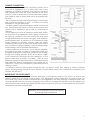
Venting Into A Masonry Chimney
Venting Into A Fireplace
Many people may wish to convert an existing replace to heater use. Usually, safe connection of stovepipe
to a masonry chimney requires more effort than connection to a prefabricated chimney. Always remember to
inspect the masonry chimney and replace. If necessary, clean the ue and smoke shelf before beginning your
installation. Install the heater into the replace so that the system can be dismantled for cleaning and inspection.
Before deciding to convert your replace, keep in mind that some replaces and existing chimneys are unsafe.
They must be structurally sound, and the ue liner must be in good condition. Do not use a chimney if it is unlined
(should have a re clay tile liner to protect brickwork). Have it relined professionally. Clearances to combustibles
are explained in the previous section on masonry chimneys. If you have any questions regarding the condition
of the chimney, consult a qualied engineer, competent mason, or knowledgeable inspector.
Many prefabricated replaces fall into the "zero-clearance replace" category. This is a factory-built metal
replace with multi-layered construction. It is designed to provide enough insulation and/or air cooling so that
the base, back and sides can be safely placed in direct contact with combustible oors and walls. Although
many prefabricated replaces have been tested by nationally recognized organizations for use as replaces,
they have not been tested to accept heaters. In fact, their use as such may void the manufacturer's warranty.
Steel-lined replaces, on the other hand, can be used with heaters. These units use a 1/4-inch rebox liner and
an air chamber in connection with 8 inches of masonry to meet code. They contain all the essential parts of a
replace, rebox, throat, smoke shelf, and smoke chamber. Many of them look exactly like a masonry replace
and must be checked closely for above requirements before installing a wood heater into them.
Another method frequently used by some people is to vent the heater directly into the replace. This does not
meet code since the heater is being vented into another appliance - the replace. This method should not be
attempted because combustion products will deposit and build up in the rebox or replace. Be certain not to
install a hazard in your house. You will void your warranty with this installation.
CAUTION: Not all replaces are suitable for installation of a wood heater.

9
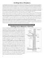
"Fireplace" Installation
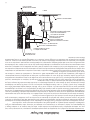
FIREPLACE INSTALLATION
Connection of the stovepipe directly into the existing masonry chimney over the replace opening is a more
desirable method. This installation performs better, yielding more heat and better draft; it is also easy to clean
and inspect for creosote. Before beginning this type of installation plan carefully; a high degree of skill is required
to insure safety.
An entry port for the stovepipe must be cut through the chimney with minimum damage to the reclay liner.
Some involved measurements may be required to locate the ue liner exactly. Before cutting, take time to mark
the size and position of the entry port. Position the entry port so that at least 8 inches of the ue liner remains
below the port.
Keep in mind that wood mantels and combustible trim around the replace must have adequate clearances
from the heater and stovepipe or must be protected in an approved manner. Also, be sure to leave at least an
18 inch clearance between the top of the stovepipe and the combustible ceiling or other combustibles. Placing
the center of the entry port 2 feet below the ceiling will insure proper clearance for 6-inch, 8-inch, and 10-inch
stovepipes. Next, install a reclay (at least 5/8 inch thick) or metal thimble, being sure that the thimble is ush with
the inner ue lining, secure the thimble in place with refractory mortar. The thimble should be surrounded on all
sides with 8 inches of brickwork (solid masonry units) or 24 inches of stone.
Install the stovepipe as far as possible into the thimble, but not past the inside of the ue lining. There should
be a small airspace (approximately 1/2 inch) between the stovepipe and thimble, allowing for expansion of the
stovepipe. Seal this airspace with high-temperature caulking or ceramic wool. Do not use the Type B installation
(not illustrated in this manual), that is, venting up through the replace opening, regardless of whether the
replace opening is closed.
Masonry chimneys have several positive attributes: If properly built, they are quite durable, and most homeowners
consider them more attractive perhaps than an unenclosed factory built chimney. And, if the chimney is located
within the connes of the house (that is, not attached to an exterior wall), its mass alone will store heat longer and
continue to release the heat long after the re has died. Masonry chimneys have many disadvantages though.
Masonry chimneys constructed on an exterior wall are exposed to cold outdoor temperatures, promoting
greater heat loss, higher accumulations of creosote, and reduced draft which leads to poorer heater or furnace
performance.

10
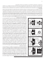
COMBUSTIBLE WALL CHIMNEY CONNECTOR PASS-THROUGHS
Method A. 12” (304.8 mm) Clearance to Combustible Wall
Member: Using a minimum thickness 3.5” (89 mm) brick and a
5/8” (15.9 mm) minimum wall thickness clay liner, construct a
wall pass-through. The clay liner must conform to ASTM C315
(Standard Specication for Clay Fire Linings) or its equivalent.
Keep a minimum of 12” (304.8 mm) of brick masonry between
the clay liner and wall combustibles. The clay liner shall run
from the brick masonry outer surface to the inner surface of the
chimney ue liner but not past the inner surface. Firmly grout or
cement the clay liner in place to the chimney ue liner.
Method B. 9” (228.6 mm) Clearance to Combustible Wall
Member: Using a 6” (152.4 mm) inside diameter, listed, factory-
built Solid-Pak chimney section with insulation of 1” (25.4 mm) or
more, build a wall pass-through with a minimum 9” (228.6 mm)
air space between the outer wall of the chimney length and
wall combustibles. Use sheet metal supports fastened securely
to wall surfaces on all sides, to maintain the 9” (228.6 mm) air
space. When fastening supports to chimney length, do not
penetrate the chimney liner (the inside wall of the Solid-Pak
chimney). The inner end of the Solid-Pak chimney section shall
be ush with the inside of the masonry chimney ue, and sealed
with a non-water soluble refractory cement. Use this cement to
also seal to the brick masonry penetration.
Method C. 6” (152.4 mm) Clearance to Combustible Wall
Member: Starting with a minimum 24 gage (.024” [.61 mm])
6” (152.4 mm) metal chimney connector, and a minimum 24
gage ventilated wall thimble which has two air channels of 1”
(25.4 mm) each, construct a wall pass-through. There shall be a
minimum 6” (152.4) mm separation area containing berglass
insulation, from the outer surface of the wall thimble to wall
combustibles. Support the wall thimble, and cover its opening
with a 24-gage minimum sheet metal support. Maintain the 6”
(152.4 mm) space. There should also be a support sized to t
and hold the metal chimney connector. See that the supports
are fastened securely to wall surfaces on all sides. Make sure
fasteners used to secure the metal chimney connector do not
penetrate chimney ue liner.
Method D. 2” (50.8 mm) Clearance to Combustible Wall
Member: Start with a solid-pak listed factory built chimney
section at least 12” (304 mm) long, with insulation of 1” (25.4
mm) or more, and an inside diameter of 8” (2 inches [51 mm]
larger than the 6” [152.4 mm] chimney connector). Use this as a
pass-through for a minimum 24-gauge single wall steel chimney
connector. Keep solid-pak section concentric with and spaced
1” (25.4 mm) off the chimney connector by way of sheet
metal support plates at both ends of chimney section. Cover
opening with and support chimney section on both sides with
24 gage minimum sheet metal supports. See that the supports
are fastened securely to wall surfaces on all sides. Make sure
fasteners used to secure chimney ue line.
NOTES: Connectors to a masonry chimney, excepting method B, shall extend in one continuous section through
the wall pass-through system and the chimney wall, to but not past the inner ue liner face.
A chimney connector shall not pass through an attic or roof space, closet or similar concealed space, or a oor,
or ceiling.

11
1. Crimped end of the pipe must be installed toward the
heater. The pipe should slide inside the ue collar. The
pipe should be rmly attached to the ue collar with 3
screws and sealed with furnace cement.
2. Slope any horizontal pipe upward toward the chimney
at least 1/4 " inch for each foot of horizontal run.
3. You must have at least 18" inches clearance between
any horizontal piping and the ceiling.
4. The pipe cannot extend into the chimney ue.(Fig. 8)
5. Seal each connector pipe joint with furnace cement. Also seal the pipe at the chimney.
6. Use 3 sheet metal screws at each joint to make the piping rigid.
7. It is recommended that no more than two (2) 90 degree bends be used in the stove pipe installation as more
than two (2) may decrease the amount of draw and possibly cause smoke spillage.
8. The chimney connector must not pass through an attic or roof space, closet, or any concealed space, or
oor, ceiling, wall or combustible construction.
WOODSTOVE UTILIZATION
Do not burn manufactured logs made of wax impregnated sawdust or logs with any
chemical additives. Manufactured logs made of 100% compressed sawdust can be
burned, but be careful burning too much of these logs at the same time. Start with one
manufactured log and see how the stove reacts. You can increase the number of logs
burned at a time to making sure the temperature never rises higher than 475 °F (246 °C) on
a magnetic thermometer for installation on single wall stove pipes or 900 °F (482 °C) on a
probe thermometer for installation on double wall stove pipe. The thermometer should be
placed about 18” (457 mm) above the stove. Higher temperatures can lead to overheat
and damage your stove.
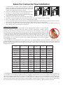
Your heating unit was designed to burn wood only; no other materials should be burned. Waste and other
ammable materials should not be burned in your stove. Any type of wood may be used in your stove, but
specic varieties have better energy yields than others. Please consult the following table in order to make the
best possible choice.
It is EXTREMELY IMPORTANT that you use DRY WOOD only in your wood stove. The wood should have dried for 9
to 15 months, such that the humidity content (in weight) is reduced below 20% of the weight of the log. It is very
important to keep in mind that even if the wood has been cut for one, two or even more years, it is not necessarily
dry, if it has been stored in poor conditions. Under extreme conditions it may rot instead of drying. This point
cannot be over stressed; the vast majority of the problems related to the operation of a wood stove is caused by
the fact that the wood used was too damp or had dried in poor conditions. These problems can be:
Rules For Connector Pipe Installation
RIGHT WRONG WRONG
TYPE
WEIGHT
(LBS. CU. FT., DRY)
PER CORD
EFFICIENCY
RANKING
SPLITS
MILLIONS
BTU’s/CORD
Hickory 63 4500 1.0 Well 31.5
White Oak 48 4100 .9 Fair 28.6
Red Oak 46 3900 .8 Fair 27.4
Beech 45 3800 .7 Hard 26.8
Sugar Maple 44 3700 .6 Fair 26.2
Black Oak 43 3700 .6 Fair 25.6
Ash 42 3600 .5 Well 25.0
Yellow Birch 40 3400 .4 Hard 23.8
Red Maple 38 3200 .3 Fair 22.6
Paper Birch 37 3100 .3 Easy 22.1
Elm/Sycamore 34 2900 .2 Very Difcult 20.1
Red Spruce 29 1800 .1 Easy 16.1

12
- ignition problems
- creosote build-up causing chimney res
- low energy yield
- blackened windows
- incomplete log combustion
Smaller pieces of wood will dry faster. All logs exceeding 6” in diameter should be split. The wood should not be
stored directly on the ground. Air should circulate through the cord. A 24” to 48” air space should be left between
each row of logs, which should be placed in the sunniest location possible. The upper layer of wood should be
protected from the element but not the sides.
VISIBLE SMOKE
The amount of visible smoke being produced can be an effective method of determining how efciently the
combustion process is taking place at the given settings. Visible smoke consist of unburned fuel and moisture
leaving your stove. Learn to adjust the air settings of your specic unit to produce the smallest amount of visible
smoke. Wood that has not been seasoned properly and has a high wood moisture content will produce excess
visible smoke and burn poorly.
EFFICIENCY
Efciencies can be based on either the lower heating value (LHV) or the higher heating value (HHV) of the fuel.
The lower heating value is when water leaves the combustion process as a vapor, in the case of wood stoves the
moisture in the wood being burned leaves the stove as a vapor. The higher heating value is when water leaves
the combustion process completely condensed. In the case of wood stoves this would assume the exhaust gases
are room temperature when leaving the system, and therefore calculations using this heating value consider
the heat going up the chimney as lost energy. Therefore, efciency calculated using the lower heating value of
wood will be higher than efciency calculated using the higher heating value. In the United States all wood stove
efciencies should be calculated using the higher heating value. The best way to achieve optimum efciencies
is to learn the burn characteristic of your appliance and burn well-seasoned wood. Higher burn rates are not
always the best heating burn rates; after a good re is established a lower burn rate may be a better option for
efcient heating. A lower burn rate slows the ow of usable heat out of the home through the chimney, and it
also consumes less wood.
TESTING YOUR WOOD
When the stove is thoroughly warmed, place one piece of split wood (about ve inches in diameter) parallel
to the door on the bed of red embers. Close the door. If ignition of the piece is accomplished within 90 seconds
from the time if was placed in the stove, your wood is correctly dried. If ignition takes longer, your wood is damp. If
your wood hisses and water or vapor escapes at the ends of the piece, your wood is soaked or freshly cut. Do not
use this wood in your stove. Large amounts of creosote could be deposited in your chimney, creating potential
conditions for a chimney re.
TAMPER WARNING
This wood heater has a manufacturer-set minimum low burn rate that must not be altered. It is against federal
regulations to alter this setting or otherwise operate this wood heater in a manner inconsistent with operating
instructions in this manual.
OPERATIONAL TIPS FOR GOOD, EFFICIENT, AND CLEAN COMBUSTION
• Get the appliance hot and establish a good coal bed before adjusting to a low burn rate (this may take 30
minutes or more depending on your wood)
• Use smaller pieces of wood during start-up and a high burn rate to increase the stove temperature
• Be considerate of the environment and only burn dry wood
• Burn small, intense res instead of large, slow burning res when possible
• Learn your appliance's operating characteristics to obtain optimum performance
• Burning unseasoned wet wood only hurts your stoves efciency and leads to accelerated creosote buildup
in your chimney
BUILDING A FIRE
The top down method of re building is recommended for this appliance. Place the largest pieces of wood on
the bottom, laid in parallel and close together. Smaller pieces are placed in a second layer, crossways to the
rst. A third layer of still smaller pieces is laid crossways to the second, this time with some spaces between. Then
a fourth layer of loose, small kindling and twisted newspaper sheets tops off the pile.

13
WOOD FUEL
Use Hardwood that has been split and air-dried to obtain maximum burning efciency.
Lighting Instructions
1. Open door and place paper and kindling in the rebox.
2. Light the re and close the doors until the kindling is burning.
3. Open the doors and add fuel as desired.
EXTENDED OPERATION
Fuel should be added in small amounts to give more complete combustion and uniform room temperature. Do
not load fuel above the top of the rebrick. Empty the ashes regularly. Do not allow ashes to build up. Dispose
of hot ashes properly in a metal container with a lid.
SERVICE HINTS
Do not expect a heater to draw. It is the chimney that creates the draft. Smoke spillage into the house or
excessive buildup of water or creosote in the chimney are warnings that the chimney is not functioning properly.
Correct problem before using heater. Possible causes are:
1. The connector pipe may push into the chimney too far, stopping the draft.
2. Do not connect two heaters into the same chimney ue.
3. The chimney used for a heater must not be used to ventilate the cellar or basement. If there is a cleanout
opening at the base of the chimney, It must be closed tightly.
4. If the chimney is operating too cool, water will condense in the chimney and run back into the stove.
Creosote formation will be rapid and may block the chimney. Operate the heater at a high enough re to
keep the chimney warm preventing this condensation.
5. If the re burns well but sometimes smokes or burns slowly, it may be caused by the chimney top being lower
than another part of the house or a nearby tree. The wind blowing over a house or tree, falls on top of the
chimney like water over a dam, beating down the smoke. The top of the chimney should be at least 3 feet
above the roof and be at least to 2 feet higher than any point of the roof within 10 feet.
CHIMNEY MAINTENANCE
• Failure to clean and maintain this unit as indicated can result in poor performance and safety hazards.
• Never perform any inspections, cleaning, or maintenance on a hot heater.
• Do not operate heater with broken glass, leakage of ue gas may result.
• Keep the Chimney and Chimney Connector clean and in good condition.
FLUE GAS SYSTEM
Creosote Formation and Need for Removal When wood is burned slowly, it produces tar and other organic
vapors, which combine with expelled moisture to form creosote. The creosote vapors condense in the relatively
cool chimney ue of a slow-burning re. As a result, creosote residue accumulates on the ue lining. When ignited
this creosote makes an extremely hot re. The chimney connector and chimney should be inspected at least
once every two months during the heating season to determine if a creosote buildup has occurred. If creosote
has accumulated it should be removed to reduce the risk of a chimney re.
Inspection and Removal – The chimney connector and chimney should be inspected at least twice monthly
during the heating season to determine if a creosote buildup has occurred. If creosote has accumulated, it
should be removed to reduce the risk of a chimney re. Inspect the system at the heater connection and at the
chimney top. Cooler surfaces tend to build creosote deposits quicker, so it is important to check the chimney
from the top as well as from the bottom. The creosote should be removed with a brush specically designed for
the type of chimney in use. A qualied chimney sweep can perform this service. It is also recommended that
before each heating season the entire system be professionally inspected, cleaned and, if necessary, repaired.
To clean the chimney, disconnect the vent from the heater.
WARNING: Operate only with the feed and ash doors fully closed. Keep seals in good condition.
WARNING: Never store ammable liquids, especially gasoline. In the vicinity of the heater.
CAUTION: Never use gasoline, gasoline-type lantern fuel, kerosene, charcoal lighter uid, or ammable liquids to
start or "freshen up" a re in the heater. Keep all such liquids well away from the heater while it is in use.
CAUTION: Overring the appliance may cause a house re. If a unit or chimney connector glows, you are
overring. Attempts to achieve heat output rates that exceed heater design specications can result in
permanent damage to the heater and to the catalytic combustor if so equipped.

14
Chimney res burn very hot. If the chimney connector should glow red, immediately call the re department,
then reduce the re by pouring a large quantity of coarse salt, baking soda or cool ashes on top of the re in the
rebox.
ASHES - REMOVAL AND DISPOSAL
Whenever ashes get 3 to 4 inches deep in your rebox or ash pan, and when the re has burned down and
cooled, remove excess ashes. Leave an ash bed approximately 1 inch deep on the rebox bottom to help
maintain a hot charcoal bed.
DISPOSAL OF ASHES
Ashes should be placed in a metal container with a tight tting lid. The closed container of ashes should be
placed on a noncombustible oor or on the ground, well away from all combustible material, pending nal
disposal. If the ashes are disposed of my burial in soil or otherwise locally dispersed, they should be retained in the
closed container until all cinders have thoroughly cooled.
Other waste shall not be placed in the same container as the ashes.
Ashes should never be placed in a wooden, cardboard, or plastic container, nor in a paper or plastic bag, no
matter how long the re has been out. Coals have been known to stay hot for several days when embedded in
ashes.
NEVER OPERATE THIS HEATER WITH THE BRICK CRADLE OR THE ASH PAN REMOVED OR DAMAGED.
SMOKE AND CO MONITORS
Burning wood naturally produces smoke and carbon monoxide(CO) emissions. CO is a poisonous gas when
exposed to elevated concentrations for extended periods of time. While the modern combustion systems in
heaters drastically reduce the amount of CO emitted out the chimney, exposure to the gases in closed or conned
areas can be dangerous. Make sure your stove gaskets and chimney joints are in good working order and sealing
properly to ensure unintended exposure. It is recommended that you use both smoke and CO monitors in areas
having the potential to generate CO.
GLASS REPLACEMENT INSTRUCTIONS
This unit’s door uses a 1/4 X 1/2 diameter rope gasket.
6. Be sure heater has cooled before beginning.
7. Remove 12, 8-32 x ¼ screws and glass retainers with screw driver.
8. Remove damaged glass (2).
9. To reinstall glass, follow steps 1-2 in reverse order. Be sure to replace the gasket on the glass. Do not build the
re too close to the glass, unless the appliance is specically designed to operate in this manner.
10. Caution: Do not operate with broken glass.
11. When removing broken glass, wear thick gloves, and safety glasses. Keep children away. Discard broken
glass.
12. Use part no. 891108 only, to replace broken glass. Glass dimensions (8⅞ x 20¼ x 5mm) high temp resistant
ceramic glass.
13. Warning: Do not slam door or strike glass. Slamming door or striking glass may cause glass to break.
14. Caution: Do not build re directly on glass.
15. Warning: Do not use substitute materials.
16. Warning: Do not use abrasive cleaners. Abrasive cleaners may damage the glass.
17. Allow the stove to cool before cleaning the glass. DO NOT clean the glass when it is HOT!
18. When cool, clean the glass with a specialized glass cleaner available at your dealer. Keeping the glass
clean will result in maximum ame visualization.
AIR TUBES
The air tubes assembled in this unit are designed to provide an accurate mix of secondary air to insure the
highest efciency. Any damage or deterioration of these tubes may reduce the efciency of combustion. The
air tubes are held in position by either screws or snap pins. Locate these to either side of the tube and remove to
allow the tube to be removed and replaced.
CAUTION: A chimney re may cause ignition of wall studs or rafters which you thought were a safe distance from
the chimney. If you have a chimney re, have your chimney inspected by a qualied person before using again
CAUTION: Do not burn your stove with the ring door open, this could cause an over ring situation.

15
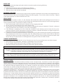
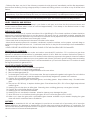
Repair Parts
Key Part No. Description Qty.
1 69427 Ash Pan 1
2 40292 Flue Collar 1
3 891492 Blower Assembly (B36) 1
4 25300 Blower Housing 1
5 25305 Deector, Air 1
1
5
2
3
4
In order to maintain warranty, components must be replaced using original manufacturers parts purchased
through your dealer or directly from the appliance manufacturer. Use of third party components will void the
warranty.
Key Part No. Description Qty.
1 891135 Handle 1
2 891112 Feed Door 1
3 891108 Glass w/King Logo 1
4 88087 Door Glass Gasket 1
5 891114 Top/Side Window Bracket 4
6 891115 Bottom Window Bracket 1
7 891113 Feed Door Gasket 1
1
2
3
4
6
5
7
5
4
1
3
2
Key Part No. Description Qty.
1 89066 Firebrick (4-1/2 X 9) 15
2 69458 Plug, Ash 1
3 24103 Firebrick, Half (4-1/2 X 4-1/2) 2
4 86645 Tube (Ø7/32), Secondary Air 1
5 88250 Board, Ceramic Fiber 2
1
2
3
4
6
5
7
5
4
1
3
2

16
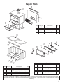
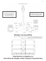
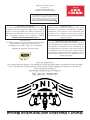
Wiring Diagram
WARNING: do not route the supply
cord near or across hot surfaces!
CAUTION: The blower assembly
must be disconnected from the
source of electrical supply before
attempting any maintenance.
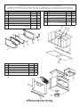
Brick Placement - (Top Inside View Of Firebox)
1. Insert right & left side rebrick as shown.
2. Insert rear rebrick as shown.
3. Insert bottom 1/2 rebrick and ash dump cover as shown.
1/2
BRICK
1/2
BRICK

Notes

Notes

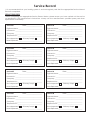
It is recommended that your heating system is serviced regularly and that the appropriate Service Interval
Record is completed.
SERVICE PROVIDER
Before completing the appropriate Service Record below, please ensure you have carried out the service
as described in the manufacturer’s instructions. Always use the manufacturer's specied spare part when
replacement is necessary.
Service Record
Service 01 Date: _____________________
Engineer Name: ________________________________
License No.: ____________________________________
Company: _____________________________________
Telephone No.: _________________________________
Stove Inspected: Chimney Swept:
Items Replaced: ________________________________
Service 03 Date: _____________________
Engineer Name: ________________________________
License No.: ____________________________________
Company: _____________________________________
Telephone No.: _________________________________
Stove Inspected: Chimney Swept:
Items Replaced: ________________________________
Service 05 Date: _____________________
Engineer Name: ________________________________
License No.: ____________________________________
Company: _____________________________________
Telephone No.: _________________________________
Stove Inspected: Chimney Swept:
Items Replaced: ________________________________
Service 07 Date: _____________________
Engineer Name: ________________________________
License No.: ____________________________________
Company: _____________________________________
Telephone No.: _________________________________
Stove Inspected: Chimney Swept:
Items Replaced: ________________________________
Service 02 Date: _____________________
Engineer Name: ________________________________
License No.: ____________________________________
Company: _____________________________________
Telephone No.: _________________________________
Stove Inspected: Chimney Swept:
Items Replaced: ________________________________
Service 04 Date: _____________________
Engineer Name: ________________________________
License No.: ____________________________________
Company: _____________________________________
Telephone No.: _________________________________
Stove Inspected: Chimney Swept:
Items Replaced: ________________________________
Service 06 Date: _____________________
Engineer Name: ________________________________
License No.: ____________________________________
Company: _____________________________________
Telephone No.: _________________________________
Stove Inspected: Chimney Swept:
Items Replaced: ________________________________
Service 08 Date: _____________________
Engineer Name: ________________________________
License No.: ____________________________________
Company: _____________________________________
Telephone No.: _________________________________
Stove Inspected: Chimney Swept:
Items Replaced: ________________________________

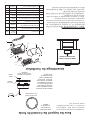
This manual will help you obtain efcient, dependable service from your
heater, and enable you to order repair parts correctly.
Keep this manual in a safe place for future reference.
When writing, always give the full model number which is on the
nameplate attached to the heater.
When ordering repair parts, always give the following information as
shown in this list /
Ce manuel vous aidera à obtenir un radiateur efcace et able, tout en
vous permettant de commander les pièces de rechange correctement.
Conservez ce manuel dans un endroit sécuritaire pour une consultation
ultérieure.
Lorsque vous effectuez une correspondance par écrit, assurez-vous de
toujours fournir le numéro de modèle qui se trouve sur la che signalétique
attachée
à l'appareil de chauffage.
Lorsque vous commandez des pièces de rechange, inscrivez toujours
les renseignements suivants, tel qu'indiqué dans cette liste:
1. The part number / Le numéro de la pièce ________________________________
2. The part description / La description de la pièce _________________________
3. The model number / Le numéro du modèle ______________________________
4. The serial number / Le numéro de série __________________________________
How To Order Repair Parts /
Comment Commander Des Pièces De Rechange
United States Stove Company
227 Industrial Park Road
South Pittsburg, TN 37380
(800) 750-2723
WWW.USSTOVE.COM
La page est en cours de chargement...
La page est en cours de chargement...
La page est en cours de chargement...
La page est en cours de chargement...
La page est en cours de chargement...
La page est en cours de chargement...
La page est en cours de chargement...
La page est en cours de chargement...
La page est en cours de chargement...
La page est en cours de chargement...
La page est en cours de chargement...
La page est en cours de chargement...
La page est en cours de chargement...
La page est en cours de chargement...
La page est en cours de chargement...
La page est en cours de chargement...
La page est en cours de chargement...
La page est en cours de chargement...
La page est en cours de chargement...
La page est en cours de chargement...
-
 1
1
-
 2
2
-
 3
3
-
 4
4
-
 5
5
-
 6
6
-
 7
7
-
 8
8
-
 9
9
-
 10
10
-
 11
11
-
 12
12
-
 13
13
-
 14
14
-
 15
15
-
 16
16
-
 17
17
-
 18
18
-
 19
19
-
 20
20
-
 21
21
-
 22
22
-
 23
23
-
 24
24
-
 25
25
-
 26
26
-
 27
27
-
 28
28
-
 29
29
-
 30
30
-
 31
31
-
 32
32
-
 33
33
-
 34
34
-
 35
35
-
 36
36
-
 37
37
-
 38
38
-
 39
39
-
 40
40


United States Stove 2016EB Le manuel du propriétaire
- Catégorie
- Cheminées
- Taper
- Le manuel du propriétaire
dans d''autres langues
Documents connexes
-
United States Stove AWC21M Le manuel du propriétaire
-
United States Stove VG900 Le manuel du propriétaire
-
-
-
United States Stove TR004 Le manuel du propriétaire
-
Ashley Hearth Products AF1300E Le manuel du propriétaire
-
-
Autres documents
-
-
-
Pleasant Hearth HWS-227202 Series Manuel utilisateur
-
-
US Stove US1269E Le manuel du propriétaire
-
United States Stove Company VG1820 Le manuel du propriétaire
-
US Stove Company US1800E Le manuel du propriétaire
-
-
-