Thermo Fisher Scientific TSG Series Manuel utilisateur
- Taper
- Manuel utilisateur

General Purpose Freezers
TSG Series
Installation and Operation
330026H01 • Revision C • 10/05/2020

IMPORTANT Read this instruction manual. Failure to follow the instructions in this manual can result in
damage to the unit, injury to operating personnel, and poor equipment performance.
CAUTION All internal adjustments and maintenance must be performed by qualified service personnel.
Material in this manual is for informational purposes only. The contents and the product it describes are
subject to change without notice. Thermo Fisher Scientific makes no representations or warranties with
respect to this manual. In no event shall Thermo be held liable for any damages, direct or incidental, arising
from or related to the use of this manual.
© 2020 Thermo Fisher Scientific Inc. All rights reserved.
For your future reference and when contacting the factory, have the following information readily
available. It can be found on the data plate attached to your unit.
Model Number:
Serial Number:
The following information, if available, is helpful for contacting the factory.
Date Purchased:
Purchase order number:
Source of Purchase:
(manufacturer or specific agent/rep organization)

Contents
Model .......................................................................... 1
Safety Precautions....................................................... 2
Unpacking ................................................................... 3
Packing List ................................................................. 3
General Recommendations.......................................... 4
Temperature Monitoring ........................................... 4
Intended Use............................................................ 4
Initial Loading ........................................................... 4
Operating Standards.................................................... 5
Unit Specifications.................................................... 5
Installation.................................................................... 6
Location................................................................... 6
Leveling the Unit....................................................... 6
Pallet Removal and Caster Installation Instructions ... 6
Wiring....................................................................... 8
Shelves .................................................................... 10
Installation Instructions ............................................. 10
Door Operation ........................................................ 10
Remote Alarm .......................................................... 10
Final Checks ............................................................ 11
Startup......................................................................... 12
Initial Startup ............................................................ 12
Product Loading and Unloading Guidelines.............. 12

Operation..................................................................... 13
Control Panel ........................................................... 13
Temperature Set point ............................................. 14
Alarms...................................................................... 14
Controller Parameter Settings................................... 15
Maintenance ................................................................ 19
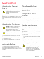
Cleaning the Cabinet Interior .................................... 19
Cleaning the Condenser........................................... 19
Automatic Defrost .................................................... 19
Time based Defrost.................................................. 19
Temperature based Defrost...................................... 19
Gasket Maintenance ................................................ 19
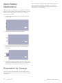
Alarm Battery Maintenance ...................................... 20
Preparation for Storage ............................................ 20
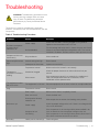
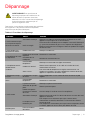
Troubleshooting........................................................... 21
End of Life Care ........................................................... 22
Warranty...................................................................... 23
Regulatory Compliance................................................ 24
Product Safety ......................................................... 24
Electromagnetic Compatibility .................................. 24
Energy Efficiency...................................................... 25
Additional Regulations and Markings........................ 25
Contact Information .................................................... 27

General Purpose Freezers Model | 1
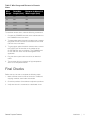
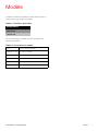
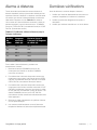
Model
The following table shows the models covered in this
operation and installation manual.
The annotation of model numbers is given in the following
table:
Table 1. Applicable Models
Freezers
TSG25FSSA
TSG49FSSA
Table 2. Model Annotation
Series TSG (Thermo Scientific)
Size (cu.ft) 25, 49
Type F = Freezer
Exterior S = Stainless
Door Type S = Solid
Voltage A = 115 V / 60 Hz

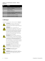
2 | Safety Precautions General Purpose Freezers
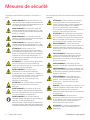
Safety Precautions
In this manual, the following symbols and conventions are
used.
Below are important safety precautions that apply to this
product.
WARNING: This symbol when used alone
indicates important operating instructions which
reduce the risk of injury or poor performance of
the unit.
WARNING: This symbol indicates potentially
hazardous situations which, if not avoided, could
result in serious injury or death.
WARNING: This symbol indicates situations
where dangerous voltages exist and potential for
electrical shock is present.
WARNING: This symbol indicates potentially
hazardous situations, which if not avoided could
result in fire.
CAUTION: This symbol, in the context of a
CAUTION, indicates a potentially hazardous
situation which if not avoided could result in
minor to moderate injury or damage to the
equipment. This indicates a situation which may
result in property damage.
CAUTION: This symbol indicates surfaces which
may become hot during use and may cause a
burn if touched with unprotected body parts.
WARNING: Before installing, using or
maintaining this product, be sure to read the
manual and product warning labels carefully.
Failure to follow these instructions may cause the
product to malfunction, which could result in
injury or damage.
CAUTION: This symbol indicates possible pinch
points which may cause personal injury.
WARNING: The snowflake symbol indicates low
temperatures and risk of frost bite. Do not touch
bare metal or samples with unprotected body
parts.
WARNING: This symbol indicates a need to use
gloves during the indicated procedures. If
performing decontamination procedures, use
chemically resistant gloves. Use insulated gloves
for handling samples and when using liquid
nitrogen.
CAUTION: Use this product only in the way
described in the product literature and in this
manual. Before using it, verify that this product is
suitable for its intended use. If the equipment is
used in a manner not specified by the
manufacturer, the protection provided by the
equipment may be impaired.
CAUTION: Do not modify system components,
especially the controller. Use OEM exact
replacement equipment or parts. Before use,
confirm that the product has not been altered in
any way.
WARNING: Your unit must be properly grounded
in conformity with national and local electrical
codes. Do not connect the unit to overloaded
power sources.
WARNING: Disconnect the unit from all power
sources before cleaning, troubleshooting, or
performing other maintenance on the product or
its controls.
WARNING: This unit is not for storage of
flammable materials.
WARNING: Units are charged with hydrocarbon
refrigerant (R290). Only qualified service
personnel should service this unit.
WARNING: Unauthorized repair of your unit will
invalidate your warranty. Contact Technical
Service at 1-866-984-3766 for additional
information.
DANGER: Risk of fire or explosion. Flammable
refrigerant used to be repaired only by trained
service personnel. Do not puncture refrigerant
tubing.
WARNING: No equipment that uses an open
flame should be placed inside the Freezer. This
will harm the unit, hamper functionality and
compromise your safety.
CAUTION: Do not use any battery powered or
externally-powered equipment in the Freezer.

General Purpose Freezers Unpacking | 3
Unpacking
At delivery, examine the exterior for physical damage while
the carrier’s representative is present. If exterior damage is
present, carefully unpack and inspect the unit and all
accessories for damage.
If there is no exterior damage, unpack and inspect the
equipment within five days of delivery. If you find any damage,
keep the packing materials and immediately report the
damage to the carrier.
Do not return goods to the manufacturer without
written authorization.
When submitting a claim for shipping damage, request that
the carrier inspect the shipping container and equipment.
Packing List
Along with the unit, following things will be packed:
• Installation and Operation manual.
• Door Lock Key and Power Key Switch is wire tied to the
pilaster on the upper top front.
• Small bag with shelving clips
• Shelves
•Casters

4 | General Recommendations General Purpose Freezers
General Recommendations
This section includes some general recommendations for
your unit.
Temperature Monitoring
Intended Use
The freezers described in this manual are lab-grade, general
purpose units intended to store non-critical samples at
operating temperatures between -12ºC to -27ºC.
These units are not registered as medical devices or any other
medical applications by a medical device regulatory body
(e.g. FDA): that is, they have not been evaluated for the
storage of samples for diagnostic use or for samples to be re-
introduced to the body.
These units are not intended for use in classified hazardous
locations, nor to be used for the storage of flammable or
corrosive inventory.
These freezers are not suitable for outdoor location.
Initial Loading
Allow the unit to operate at the desired temperature for a
minimum of 24 hours before loading.
Load the unit one shelf at a time, starting from bottom to top
shelf. After loading each shelf, allow the unit to recover to the
desired set point before loading the next shelf. Repeat this
process until the unit is fully loaded. Refer to the section
Shelves for shelf load ratings.
IMPORTANT NOTE: We recommend the use of
a redundant and independent temperature
monitoring system so that the unit can be
monitored continuously for performance
commensurate with the value of product stored.
CAUTION: Storage of unsealed corrosive
substances may cause the interior of the unit to
corrode.
CAUTION: Failure to follow these procedures or
overloading the unit may cause undue stress on
the compressors or jeopardize user product
safety.

General Purpose Freezers Operating Standards | 5
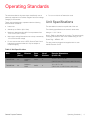
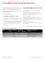
Operating Standards
The units described in this manual are classified for use as
stationary equipment in a Pollution Degree 2 and Over voltage
Category II environment.
These units are designed to operate under the following
environmental conditions:
• Indoor use
• Altitude up to 2000 m (6512 feet)
• Maximum relative humidity 60% for temperatures from
15°C to 32°C (59°F to 90°F)
• Main supply voltage fluctuations not to drop or exceed by
10% of the nominal voltage
• Do not connect the unit to a GFCI (Ground Fault Circuit
Interrupter) protected outlet as it may be subject to
nuisance tripping
• Do not run this unit off extension cords
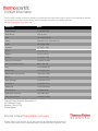
Unit Specifications
The data label is located on top left side of the unit.
The following specifications are same for all the units
Voltage = 115 V / 60 Hz
Amps - Refer to data label for unit rating. The power supply
cord plug indicates the wall circuit breaker rating at 15A.
Power Plug = NEMA 5-15P
This plug must be plugged into/supplied with it's own
individual branch circuit.
Table 3. Unit Specifications
Unit Size
(Cu.ft.)
Exterior Door
Ty p e
No.of
Shelves
Exterior Dimensions
(H x W x D)
TSG25FSSA 25 Stainless
Steel Solid 478.25" x 30.7" x 31.88"
(1987.55 mm x 779.78 mm x 809.752 mm)
TSG49FSSA 49 Stainless
Steel Solid 878" x 52.7" x 32"
(1981.2 mm x 1338.58 mm x 812.8 mm)

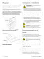
6 | Installation General Purpose Freezers
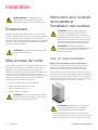
Installation
Location
Install the unit on a level area free from vibration. Refer to data
label on unit for more details about the installation clearance.
Do not position the equipment in direct sunlight or near
heating diffusers, radiators or other sources of heat.
Leveling the Unit
The Freezer must be level in order to provide adequate
condensation drainage as well as proper door alignment and
operation. The Freezer should be in its final operating location
and set so that it is firmly positioned on the floor. Level the
cabinet front to rear and side-to-side using the corner leveling
screws. The front leveling screws are accessed by removing
the base grill, as described below:
1. Remove the lower grill attachment screws
2. Grasp the grill with both hands
3. Lift the grill approximately 1/2"
4. Pull grill away from the Freezer
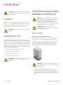
Pallet Removal and Caster
Installation Instructions
With Forklift
Required Tools for Double Door Unit:
Phillips head screwdriver, 5/16"-18" bolts and follow local
PPE and staffing procedures to remove the unit safely.
The following instructions demonstrate how to remove the
cabinet from its shipping base (pallet), install the casters
or lower legs using a fork truck. And 7/16" wrench for
removing lag bolts from the pallet as mentioned below:
1. Remove the packaging and kick plates from unit.
Remove additional packaging to access the interior of the
cabinet. Be sure to keep one cardboard corner for
subsequent step and one screw in the bottom center of
the grill.
WARNING: Do not exceed the electrical rating
printed on the data plate located on the upper left
side of the unit.
CAUTION: Do not move the unit in fully loaded
condition.
CAUTION: An unlevel unit may result in instability
and performance issues for the doors and
drawers.
CAUTION: Avoid damage to the refrigerant
tubing which may cause a refrigerant leak while
handling, moving and operating this unit.A
minimum free air space requirements of 10"X
10"X 8" room per unit must be created according
to CSA-B52-05 to avoid refrigerant leak.
CAUTION: Removal of pallet and caster
installation must be performed by an authorized
service personnel only.
CAUTION: The unit should be unpacked near
the desired location to avoid the risk of damage
while shifting.

General Purpose Freezers Installation | 7
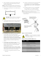
2. Using a screwdriver, remove the screw holding on the
front grill. Lift grill upwards and pull away from unit to
remove. Set aside the grill.
Note: Re-install the front grill after placing the refrigerator in
the desired location and tighten the screw with a screwdriver.
3. Remove bolts (4) holding the unit to the pallet using the
7/16" wrench.
4. Carefully position forks to lift unit from rear. Ensure unit is
fully positioned on fork truck prior to raising the forks.
5. For single door units: Raise the unit approximately six
inches to allow access to the feet and casters.
Use local PPE protocols and the appropriate number of
people to stand at the front of the unit and provide
additional support to the unit. If Leg Levelers are desired,
lower all 4 factory installed feet (using the 3/8" wrench to
loosen if necessary). If rolling casters are desired, remove
the feet and install the 4 casters and tighten using
wrench.
6. For double door units: Raise the unit approximately six
inches to allow access to the Leg Levelers.
Use local PPE protocols and the appropriate number of
people to stand at the front of the unit and provide
additional support to the unit.
If Leg Levelers are desired, lower all 4 factory installed
Leg Levelers. For casters, remove the 8 Hex Head Bolts,
8 Nuts and 8 Washers fitted with levers using the wrench
and keep aside (to be re-used to mount casters).
6a. Remove the 4 leg levelers and discard or save for
future use.
6b. Install the 2 casters with lock in the front of the cabi-
net with 8 sets of 5/16-18x1" Hex Head Bolts,
5/16" Nuts and 7/8" O.D. washer, supplied with the
package 4 sets of (2) 5/16-18 x 1 Hex Head Bolts,
Nuts.
6c. Re-use the 8 sets of 5/16-18x1" Hex Head Bolts,
5/16" Nuts and 7/8" O.D. washer to install the
2 casters without lock in the rear of the cabinet.
Note: Some casters lock and others do not. It is advised to
install the locking casters on the front of the unit.
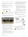
7. Remove pallet from below the unit and gently lower unit
in desired location.
Figure 1. Caster Installation
CAUTION: Always be cautious to not damage or
drop the unit when lifting the unit with forklift.
DANGER : Do not tip unit more than 10 degrees
during caster installation. Overturning may result
in serious injury or death.
Table 4. Caster Installation Spare Parts
S. No. Parts
15/16-18x1" Hex Head Bolts
(8 supplied with kit, 8 re-used)
25/16" Nuts
(8 supplied with kit, 8 re-used)
37/8" O.D. washer
(8 supplied with kit, 8 re-used)
4Caster with Lock (2 in the front)
5Caster without Lock (2 in the rear)

8 | Installation General Purpose Freezers
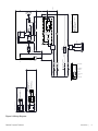
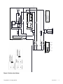
Wiring
The wiring diagram for the units is shown in Figure 2.
CAUTION: Connect the equipment to the
correct power source. Incorrect voltage can
result in severe damage to the equipment.
CAUTION: For personal safety and trouble-free
operation, this unit must be properly grounded
while in use. Failure to ground the equipment
may cause personal injury or damage to the
equipment. Always conform to the National
Electrical Code and local codes. Do not connect
the unit to overloaded power lines.
CAUTION: Always connect the unit to a
dedicated (separate) circuit. Each unit is
equipped with a service cord and plug designed
to connect it to a power outlet which delivers the
correct voltage. Supply voltage must be within
±10% of the unit rated voltage. If cord becomes
damaged, replace with a properly rated power
supply cord. Power Cord Specifications: 3-G 12
AWG, NEMA 5-15 P, 15A / 125V.
CAUTION: Never cut the grounding prong from
the service cord plug. If the prong is removed, the
warranty is invalidated.
CAUTION: Disconnect the power cord in case of
emergency.
CAUTION: Do not position the unit in a way that
impedes access to the disconnecting device or
circuit breaker in the back of the unit.

General Purpose Freezers Installation | 9
Figure 2. Wiring Diagram
6&
:+,7(
%/$&.
%52:1
6 6
',
6
6
'$1)266&21752//(5'(7$,/
&2035(6625
5(027($/$50
/,1(
1(875$/
)$1
$,56(1625
(9$36(1625
5&581&$3$&,725
6&67$57&$3$&,725
2/29(5/2$'
'$1)266&21752//(57(50,1$/
&211(&7,2132,17
&5&21752/5(/$<
/(*(1'
6((&21752//(5'(7$,/
5(027($/$50&217$&76
12&201&
5(/$<
:+,7(
&2035(6625'(7$,/93+
&855(175(/$<
6
0
&21'(16(5)$1
&
6
5
&203
2/
6((&21752//(5'(7$,/
6((&21752//(5'(7$,/
6((&21752//(5'(7$,/
.(<6:
1&
&20
&2,/
5(/$<
)250&
.(<6:
9
%$77(5<
%8==(5
/('
%/$&.
%/8(
<(//2:
%/$&. %/$&.
%/$&.
5('
%52:1
%/$&.
%52:1
:+,7(
%/8(
%/8(
%52:1
%/8(
%52:1
%/$&.
%/$&.
%/$&.
%/$&.
%/$&.
*5((1
:+,7(
*5$<
%/8(
'()5267
+($7(5
6((&21752//(5'(7$,/
'()5267
'2256(1625
(9$3)$1
)256,1*/('22581,76
)25'28%/('22581,76
'2256:,7&+
72',*,7$/,1387
32572)&21752//(5
+$51(66$1'(1'
&211(&725$5(3$572)
:+,7(%2;
72',*,7$/,1387
32572)&21752//(5
5,*+7'2256:,7&+
+$51(66$1'(1'
&211(&725$5(3$572)
:+,7(%2;
/()7'2256:,7&+
0,''/('2256:,7&+
+$51(66$1'(1'
&211(&725$5(3$572)
:+,7(%2;
5,*+7'2256:,7&+
72',*,7$/,1387
32572)&21752//(5
/()7'2256:,7&+
+
;+
3,**<%$&.
&211(&72562)
+
3,**<%$&.
&211(&7252)
+
3,**<%$&.
&211(&72562)
+
25$1*(

10 | Installation General Purpose Freezers
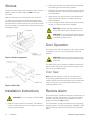
Shelves
All the units come standard with wire shelves. Each unit has a
different number of shelves. Refer to Ta ble 3 for more
information.
Maximum shelf capacity is 45 kg (100 lbs) for full shelves.
For safety during shipping, the shelves are packaged and
secured inside the cabinet. Insert the shelf support hangers
(included with the manual inside the unit) into the built-in shelf
supports (located on the inside walls of the cabinet interior) at
the desired locations.
Figure 3. Shelf Arrangement
Figure 4. Shelf Clip
Installation Instructions
1. Determine proper location for shelf clips. The reference
number on the pilaster can serve as a guide to ensure all
clips are properly located.
2. Insert top of the clip into the desired hole of the pilaster.
The retaining tab should be facing upwards.
3. Rotate the clip downwards and insert the bottom tab into
the appropriate hole. The clip may be squeezed slightly
during installation.
4. Install shelves onto clips with the product retention bar
facing upwards. Be careful to not lodge clips during
shelve installation.
5. Prior to loading the shelf, ensure that the shelf is resting
on each of 4 clips and the clips are installed.
Door Operation
The swinging door units are designed to stay open if opened
90 degrees or more. The door spring tension cannot be
adjusted.
The sliding doors can be opened completely towards left or
right. If the self-closing door does not work properly, make
sure the unit is leveled properly.
Door Seal
Note: Door seal integrity is critical for unit performance.
A loose fitting gasket allows moist air to be drawn into the
cabinet, resulting in quicker frost buildup on the cabinet walls,
longer running time, poor temperature maintenance and
increased operation cost.
Remote Alarm
All units have factory-installed remote alarm contacts that can
be used for remote alarm systems. The maximum distance
between a unit and a remote alarm depends on the wire
gauge used. Refer to Table 5 below:
The Remote alarm contacts are located on the right side of
the header panel. The three terminals are: COMMON, OPEN
ON FAIL (Normally Closed) and CLOSE ON FAIL (Normally
Open).
WARNING: Do not move this unit while loaded
CAUTION: Improper shelf clip installation may
cause shelf and/or product damage to the unit.
CAUTION: Do not overload the shelves, the unit
is designed to utilize all shelves that are supplied
in an equally spaced manner.
CAUTION: Keep hands and body parts clear of
closing doors.The moving parts create a potential
pinch point.

General Purpose Freezers Installation | 11
To install the remote alarm, make the following connections:
1. Connect the COMMON terminal on the cabinet switch to
the COMMON wire on the alarm.
2. To get an alarm when the switch contacts open, connect
the OPEN ON FAIL terminal on the cabinet to the OPEN
ON FAIL wire on the alarm.
3. To get an alarm when the switch contacts close, connect
the CLOSE ON FAIL terminal on the cabinet to the
CLOSE ON FAIL wire on the alarm. The COMMON and
CLOSE ON FAIL wires must be tied together in this
application
4. Plug the alarm system service cord into an electrical
outlet.
5. The contacts will trip in the event of high temperature
alarm or low temperature alarm.
Final Checks
Before start up, be sure to complete the following steps:
1. Make sure that the unit is free of all wood or cardboard
shipping materials, both inside and outside.
2. Check the positions of the shelves to adjust the positions.
3. Verify that the unit is connected to a dedicated circuit.
Table 5. Wire Gauge and Distance to Remote
Alarm
Wire
Gauge
Tot a l Wire
Length (feet)
Distance to Alarm 1/2
Wire Length (feet)
20 530 265
18 840 420
16 1330 665
14 2120 1060
12 3370 1685

12 | Startup General Purpose Freezers
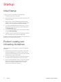
Startup
Initial Startup
To start up the unit, complete the following steps:
1. Connect the AC main power cord.
2. Insert the silver colored key in the switch and turn to the
Power On position.
3. Allow the unit to reach operating temperature before
loading it with any product. To stabilize the temperature
profile, a 24-hour waiting period is recommended.
4. If you desire to enable the power failure alarm, turn the
three position key switch one turn further clockwise to
the All Alarm On position.
5. If you have a remote alarm, hook it up at this point (refer
to section Remote Alarm).
6. If desired, lock the cabinet door using the silver colored
key. Place duplicate key copies in a safe place.
All controls should now be fully operational, the alarm active (if
enabled), and all visual indicators active.
Product Loading and
Unloading Guidelines
When loading your unit, take care to observe the following
guidelines:
• Distribute the load as evenly as possible. Temperature
uniformity depends on air circulation, which could be
impeded if the internal storage components are overfilled,
particularly at the top of the cabinet.
• For critical applications, be sure that the alarm systems
are working and active before you load any product.
• Ensure clearance between the top of the cargo and the
bottom of the internal storage components. Lack of
clearance may affect unit performance or impede
operation of the storage component.

General Purpose Freezers Operation | 13
Operation
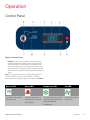
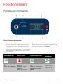
Control Panel
Figure 5. Control Panel
1. Display: During normal operation, the display shows
cabinet temperature in degree Celsius as measured by
the primary sensor. When alarm and compressor are
active, the respective LEDs are displayed. Refer to the
table below for LED display symbols. A display code will
also be visible during the functioning based on the type of
alarm.
Note: “CFu” parameter under the display settings (diS) of
controller enables conversion to Fahrenheit or Celsius.
Access controller settings using password 990, refer Table 7.
Defrost LED Alarm LED Compressor LED Fan LED
On Fixed: Defrost Active
Off: Defrost Off
On Fixed: Alarm Present
Flashing: Alarm Silenced
Off: No Alarm
On Fixed: Compressor Active
Flashing: Delay, Protection or
Activation Blocked
Off: No Alarm
On Fixed: Fan Active
Off: Fan Off

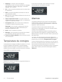
14 | Operation General Purpose Freezers
2. Defrost: This button is used to manually defrost the unit
as well as to go back from the parameter settings. During
defrost, controller will show “def” on the display.
3. SC: This button is used for selecting an option in
parameters.
4. Up: Scrolls the menu items and increases the values.
5. Down: Scrolls the menu items and decreases the values.
6. Power Fail LED: This LED indicates the power failure in
the unit.The flash light indicate power failure.
7. Key Switch: Used to turn on or off the power to the
controller and power failure alarm.
Note: This is not a primary disconnect device. Remove
the power cord to completely turn Off the unit.
8. Off: Turns off the power of the controller.
9. Power On: Turns On power to the controller and is used
to silence the power failure alarm.
10. All Alarm ON: Turns On the audible power fail alarm.
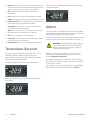
Temperature Set point
The factory default temperature set point is -23° C for all
Laboratory Freezers. Adjusting the set point is not
recommended. In case the set point has to be changed,
follow the instructions given below.
The following display shows the current temperature.
Press Up / Down button to increase / decrease setpoint
temperature.
After 30 seconds, the display automatically reverts to the
current temperature.
Alarms
The alarm system is designed to provide visual and audible
warning signals for both power failure and rise in temperature.
The alarm is equipped with a battery backup.
The power failure alarm system is activated only when the key
switch is turned to the Power Failure Alarm ON position.
Default low and high alarm values are -19°C and -27°C.
These values may be adjusted, following instructions in
section Temperature Set point.
The audible warning signal sounds when there is a power
failure, temperature alarm condition, or when the door is ajar
for more than 1 minute.
Alarm display codes for high temperature, low temperature,
sensor failure and door ajar are mentioned in Table 6.
WARNING: Low temperature, high temperature
and door ajar alarms are set to ON position by
default as soon as the controller is turned on.
These cannot be turned off.

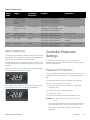
General Purpose Freezers Operation | 15
Alarm Silencing
To mute the power fail alarm, change the key-switch to Power
ON position. The power fail alarm will not be audible but the
Red LED will be displayed on the control panel.
The high temperature, low temperature, sensor failure and
door ajar alarms can be silenced by pressing any key on the
controller.
When the alarm is active, the alarm code flashes alternately
with the temperature and alarm symbol.
Once the alarm is silenced, the code stops flashing but the
temperature and the alarm symbol are still displayed.
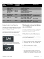
Controller Parameter
Settings
To access the controller settings, you must enter the
password and the access level determines which parameter
you can view and edit.
Password Protection
The unit is password protected except the setpoint which can
be adjusted without the password. The default password is
990.
To change the parameters,you must enter the password.
Hold “Up / Down” button for 5 seconds.
11. The display will show “PAS” after which a brief delay
changes to 000.
12. Press down arrow 10 times to get 990.
13. Press SC to confirm.
You have now entered the controller parameters menu.
Example: To change high temp alarm from -19.0ºC to
-21.0ºC
- After entering parameter menu to change High Alarm set
point.Press down arrow until ALA and press SC once.
- Press down arrow to HAt. Press SC once -19.0ºC is
displayed.
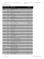
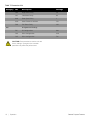
Table 6. Alarm Codes
Alarm
code
Trigger Automatic
clearance
Outputs Comments
“Hi” Air temperature is
higher than “ALA-
>Hat” for “ALA-
>Htd”
User Configured Blink “Hi” with the highest
temperature; If configured: cut in
alarm relay, beep the buzzer
High temperature alarm
“Lo” Air temperature is
less than “LAt” for
“Ltd”
User Configured Blink “Lo” with the lowest
temperature; If configured: cut in
alarm relay, beep the buzzer
Low temperature alarm
“dor” Door open for more
than “ALA->dod”
Always Blink “dor”. If configured: cut in
alarm relay, beep the buzzer
Door open alarm
“E01” “S1” error Always Blink “E01”. If configured: cut in
alarm relay, beep the buzzer
“S1” sensor failure = (short
or open)
“E02” “S2” error Always Blink “E02”. If configured: cut in
alarm relay, beep the buzzer
“S2” sensor failure = (short
or open)

16 | Operation General Purpose Freezers
- Press up arrow twice to -21.0ºC. Press SC once to save
setting.
- Then press snowflake button twice. Display will return to
cabinet temp.
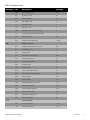
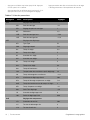
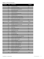
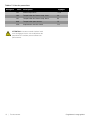
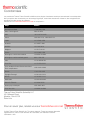
Table 7. Parameter List
Category Abv Description Settings
tHE Thermostat settings
SEt Set Point -23
SPr Set Point Adjustment Ratio 1
diF Differential 2.0
HSE High Set Point -19.0
LSE Low Set point -27.0
dEF Defrost Settings
dFt Def. Type EL
Add Adaptive Defrost Yes
dtt Def Terminate Temp 5.0 for 45 cu ft
1.6 for 25 cu ft
drt Def Reset Temp 4.3
dii Def Min Interval 1
dAi Def Max Interval 6
dit Def Min Time 5
dAt Def Max Time 60
dot Drip Off Time 1
fdd Fan Delay After Defrost 20
ftd Fan Start Temp -23.2
dFa Defrost Fan On No
dCt Defrost On Compressor Time Yes
doC Defrost by Comp. Running Time 2
dEt Defrost Start Evaporator Temp -43
ddt Defrost Delta T 2.1
idi Initial Defrost Interval 4
idd Initial Defrost Duration 999
CoP Compressor Settings
uPt Voltage Protection No
uLi Minimum Cut-in Voltage 0
uLo Minimum Cut-out Voltage 0
uHi Maximum Voltage 270
La page est en cours de chargement...
La page est en cours de chargement...
La page est en cours de chargement...
La page est en cours de chargement...
La page est en cours de chargement...
La page est en cours de chargement...
La page est en cours de chargement...
La page est en cours de chargement...
La page est en cours de chargement...
La page est en cours de chargement...
La page est en cours de chargement...
La page est en cours de chargement...
La page est en cours de chargement...
La page est en cours de chargement...
La page est en cours de chargement...
La page est en cours de chargement...
La page est en cours de chargement...
La page est en cours de chargement...
La page est en cours de chargement...
La page est en cours de chargement...
La page est en cours de chargement...
La page est en cours de chargement...
La page est en cours de chargement...
La page est en cours de chargement...
La page est en cours de chargement...
La page est en cours de chargement...
La page est en cours de chargement...
La page est en cours de chargement...
La page est en cours de chargement...
La page est en cours de chargement...
La page est en cours de chargement...
La page est en cours de chargement...
La page est en cours de chargement...
La page est en cours de chargement...
La page est en cours de chargement...
La page est en cours de chargement...
La page est en cours de chargement...
La page est en cours de chargement...
La page est en cours de chargement...
La page est en cours de chargement...
La page est en cours de chargement...
La page est en cours de chargement...
La page est en cours de chargement...
La page est en cours de chargement...
-
 1
1
-
 2
2
-
 3
3
-
 4
4
-
 5
5
-
 6
6
-
 7
7
-
 8
8
-
 9
9
-
 10
10
-
 11
11
-
 12
12
-
 13
13
-
 14
14
-
 15
15
-
 16
16
-
 17
17
-
 18
18
-
 19
19
-
 20
20
-
 21
21
-
 22
22
-
 23
23
-
 24
24
-
 25
25
-
 26
26
-
 27
27
-
 28
28
-
 29
29
-
 30
30
-
 31
31
-
 32
32
-
 33
33
-
 34
34
-
 35
35
-
 36
36
-
 37
37
-
 38
38
-
 39
39
-
 40
40
-
 41
41
-
 42
42
-
 43
43
-
 44
44
-
 45
45
-
 46
46
-
 47
47
-
 48
48
-
 49
49
-
 50
50
-
 51
51
-
 52
52
-
 53
53
-
 54
54
-
 55
55
-
 56
56
-
 57
57
-
 58
58
-
 59
59
-
 60
60
-
 61
61
-
 62
62
-
 63
63
-
 64
64


Thermo Fisher Scientific TSG Series Manuel utilisateur
- Taper
- Manuel utilisateur
dans d''autres langues
Documents connexes
-
 Thermo Fisher Scientific Undercounter ADA Laboratory Refrigerator Manuel utilisateur
-
 Thermo Fisher Scientific VALUE Series Manuel utilisateur
-
 Thermo Fisher Scientific medical Mode d'emploi
-
 Thermo Fisher Scientific TSG Series Manuel utilisateur
-
 Thermo Fisher Scientific EK20/EK30 Immersion Coolers Manuel utilisateur


