Progress Lighting P250068-31M-WB Mode d'emploi
- Catégorie
- Ventilateurs ménagers
- Taper
- Mode d'emploi
Ce manuel convient également à

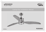
BELVA Ceiling Fan Installation Manual
93138712_B
P250068

Limited Lifetime
W
a
rranty
Progress Lighting fan motors are warranted to the original purchaser to be free of electrical and/or mechanical defects for so
long as the original purchaser owns the fan. Pull chain switches, reverse switches, capacitors and metal finishes are warranted to
be free from defects in materials or workmanship for a period of 1 year from the date of purchase. Warping of wooden or plastic
blades is not covered by this warranty nor is corrosion and/or deterioration of any finishes for fans installed within ten miles of
any sea coast. Extended warranties for ENERGY STAR®qualified products may apply.
Progress Lighting ceiling fans with built-in LED light sources, when properly installed and under normal conditions of use, are
warranted to be free from defects in material and workmanship which cause the light sources to fail to operate in accordance
with the specifications for (i) five (5) years from the date of purchase on the LED Light modules and electrical components for
fans used in single family residences, and (ii) three (3) years from the date of purchase on the LED Light modules and electrical
components for fans used in multi-family or commercial applications. LED bulbs supplied by Progress Lighting carry no
warranty other than manufacturer’s warranty. Non-LED bulbs carry no warranty.
D
ate
Purchas
ed
Sto re Pu rc has ed
M od
el
No
.
Serial No.
With proof of purchase, the original purchaser may return the defective fan to the place of purchase during the first 30 days for
replacement. After 30 days, the original purchaser MUST contact Progress Lighting at (864) 678-1000 for repair or replacement
which shall be determined in Progress Lighting’s sole discretion and shall be purchaser’s sole and exclusive remedy.
Labor and Shipping Excluded. This warranty does not cover any costs or fees associated with the labor (including, but not
limited to, electrician’s fees) required to install, remove, or replace a fan or any fan parts.
This warranty shall not apply to any loss or damage resulting from (i) normal wear and tear or alteration, misuse, abuse or
neglect, or (ii) improper installation, operation, repair or maintenance by original purchaser or a third party, including without
limitation improper voltage supply or power surge, use of improper parts or accessories, unauthorized repair (made or
attempted) or failure to provide maintenance to the fan.
THE FOREGOING WARRANTIES STATE PROGRESS LIGHTING’S ENTIRE WARRANTY OBLIGATION AND
ORIGINAL PURCHASER’S SOLE AND EXCLUSIVE REMEDY RELATED TO SUCH PRODUCTS. PROGRESS
LIGHTING IS NOT RESPONSIBLE FOR DAMAGES (INCLUDING INDIRECT, SPECIAL, INCIDENTIAL OR
CONSEQUENTIAL), DUE TO PRODUCT FAILURE, WHETHER ARISING OUT OF BREACH OF WARRANTY,
BREACH OF CONTRACT, OR OTHERWISE. THIS WARRANTY IS GIVEN IN LIEU OF ALL OTHER WARRANTIES,
WHETHER EXPRESSED OR IMPLIED, INCLUDING THOSE OF MERCHANTABILITY, FITNESS FOR A PARTICULAR
PURPOSE OR NONINFRINGEMENT.
Some states do not allow limitations on how long an implied warranty lasts or the exclusion or limitations of incidental or
consequential damages, so the above limitations and exclusions may not apply to you. This warranty gives you specific rights
and you may have other rights which vary from state to state.
Vend o r
No
.
UPC
111041

Safety Rules.....................................................................................................................................................................................
1.
Unpacking Your Fan
.......................................................................................................................................................................
2.
Installing Your Fan
..........................................................................................................................................................................
3.
Operating Your Transmitter
............................................................................................................................................................
7.
Care of Your Fan ............................................................................................................................................................................
9.
Troubleshooting
................................................................................................................................................... ............................
10.
Specifications ........................................................................................................................................................................ ..........
11.
T
a
ble of Contents

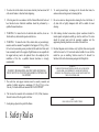
1. To reduce the risk of electric shock, insure electricity has been turned off
at the circuit breaker or fuse box before beginning.
2. All wiring must be in accordance with the National Electrical Code and
local electrical codes. Electrical installation should be performed by a
qualified licensed electrician.
3. WARNING: To reduce the risk of electrical shock and fire, do not use
this fan with any solid-state fan speed control device.
4. WARNING: To reduce the risk of fire, electric shock, or personal injury,
mount to outlet box marked "Acceptable for Fan Support of 15.9 kg (35 lbs.)
Or Less" and use mounting screws provided with the outlet box. Most outlet
boxes commonly used for the support of light fixtures are not acceptable for
fan support and may need to be replaced. Due to the complexity of the
installation of this fan, a qualified licensed electrician is strongly
recommended.
8. To avoid personal injury or damage to the fan and other items, be
cautious when working around or cleaning the fan.
9. Do not use water or detergents when cleaning the fan or fan blades. A
dry dust cloth or lightly dampened cloth will be suitable for most
cleaning.
10. After making electrical connections, spliced conductors should be
turned upward and pushed carefully up into the outlet box. The wires
should be spread apart with the grounded conductor and the
equipment-grounding conductor on one side of the outlet box.
11. Electrical diagrams are for reference only. Light kits that are not packed
with the fan must be UL Listed and marked suitable for use with the
model fan you are installing. Switches must be UL General Use
Switches. Refer to the Instructions packaged with the light kits
WARNING
TO REDUCE THE RISK OF
WARNING
PERSONAL INJURY,
DO NOT BEND THE
TO REDUCE THE RISK OF FIRE, ELECTRIC SHOCK OR PERSONAL
INJURY, MOUNT FAN TO OUTLET BOX MARKED ACCEPTABLE FOR
FAN SUPPORT.
5. The outlet box and support structure must be securely mounted and
capable of reliably supporting a minimum of 35 lbs (15.9 kg) or less.
Use only UL-listed outlet boxes marked FOR FAN
SUPPORT.
6. The fan must be mounted with a minimum of 10 ft (3.05m) clearance
from the bottom of the fan guard to the floor.
7. Avoid placing objects in the path of the blades.
1.
S
afety
R
ules
BLADE ARMS (ALSO REFERRED TO AS BRACKETS) DURING
ASSEMBLY OR AFTER INSTALLATION. DO NOT INSERT OBJECTS IN
THE PATH OF THE BLADES.
NOTE
READ AND SAVE ALL INSTRUCTIONS!

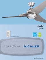
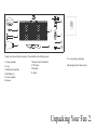
Unpack your fan and check the contents. You should have the following items: 11. Loose parts bag containing:
1. Canopy assembly
2. Cover
3. Ball/downrod assembly
4. LED bulbs (4)
5. Fixture assembly
6. Receiver
7. Remote Control Transmitter
8. 12V battery
9. Fan blade
10. Finial
a. Mounting hardware Wire nuts (6)
Unpacking
Your
Fan 2.

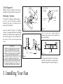
Tools
Required
Phillips screw driver, straight slot screw driver,
adjustable wrench, step ladder, and wire cutters.
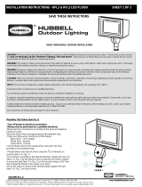
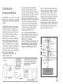
Mounting
Options
If there isn't an existing cUL listed mounting
box, then read the following instructions.
Disconnect the power by removing fuses or
turning off circuit breakers.
Outlet
box
Angled
ceiling
maximum
18.5
angle
Recessed
outlet
box
Provide strong
support
Ceiling
hanger
bracket
Secure the outlet box directly to the building
structure. Use appropriate fasteners and building
materials. The outlet box and its support must be
able to fully support the moving weight of the
fan (at least 35 lbs). Do not use plastic outlet
boxes.
Figure 1 Figure 3
Note: You may need a longer downrod to
maintain proper clearance when installing on a
steep, sloped ceiling.
WARNING
TO REDUCE THE RISK OF FIRE, ELECTRIC
SHOCK, OR OTHER PERSONAL INJURY,
MOUNT FAN ONLY TO AN OUTLET BOX
MARKED ACCEPTABLE FOR FAN SUPPORT
AND USE THE MOUNTING SCREWS
PROVIDED WITH THE OUTLET BOX. OUTLET Figure 2
Outlet
box
Figure 4 Outlet
box
BOXES COMMONLY USED FOR THE
SUPPORT OF LIGHTING FIXTURES MAY NOT
BE ACCEPTABLE FOR FAN SUPPORT AND
MAY NEED TO BE REPLACED. CONSULT A
QUALIFIED ELECTRICIAN IF IN DOUBT.
3. Installing
Your
Fan
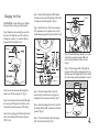
To hang your fan where there is an existing
fixture but no ceiling joist, you may need an
installation hanger bar as shown in Figure 4

Hanging the
Fan
REMEMBER
to turn off the power. Follow
the steps below to hang your fan properly:
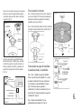
Step 1.Route the wires exiting the top of the
fan motor through the cover (D) and then
through the canopy (C) , downrod (B) and
hanger ball (J) assembly.(Fig.5)
Figure 5
Step 2. Insert the downrod (B) through the
metal cover (D) and canopy (C). (Fig 6)
Step 3. Insert the end of downrod (B) through
the connector (PP),align the two holes in the
downrod (B) and the connector (PP).(Fig.6)
Step 4. Insert a plug pin (GG) through the two
holes in the downrod (B) and the connector
(PP). (Fig.6)
Step 5. Insert the R-shaped pin (HH) though
the hole near the end of the plug pin (GG) until
it snaps into its locked position. (Fig.6)
Step 6. Install the screw (FF) to the connector
(PP), and make sure it’s tighten, Screws (FF)
should be tight against the downrod (B). (Fig.6)
Figure 6
Step 7. Insert the hanger ball (J) onto the
downrod (B), and then insert a plug pin (L)
through the hole in the downrod (B). (Fig.7)
Step 8. Insert the plug pin to the slot cut off in
the hanger ball (J) until it snaps into its locked
position. (Fig.6)
Step 9. Use the Screw(K) to lock the hanger
ball (J) to the downrod (B). (Fig.7)
Figure 7
Step 10. Install the Hanger bracket (A) on the
outlet box by using the washer (BB) and
screws(AA) provided with the Outlet box.
(Fig.8)
Step 11. Put the hanger ball (J) through the
open side of the ceiling mounting bracket (A),
and then insert the hanger ball(J) to the slot cut
off in the ceiling mounting bracket(A). (Fig.8)
Figure 8
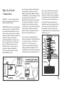
4.

Make the
Electric
Connections
WARNING: To avoid possible electrical
shock, be sure electricity is turned off at the
main fuse box before wiring.
CODE SWITCH: Codes are set by pushing dip
switches up or down. It is imperative that the
code used for both transmitter and receiver is
exactly the same, otherwise remote controller
will not work. Please note the code switch will
enable you to operate a second remote
controller independently. For example, if you
have two ceiling fans with 2 remote control
units, set 2 different codes for each set of
transmitter/receivers. This means you can
operate each ceiling fan independently.
Your remote control is ready for use after
battery installation. (Fig.9)
Figure 9
Step 1. Fan motor to Receiver Electrical and
Current Limiter Connections: Connect the
Black wire from the fan to Black wire marked
"TO MOTOR L". Connect the White wire from
the fan to the White wire marked "TO
MOTOR N" from the receiver and the White
wire from the Current limiter. Connect the
blue (light) wire to the black wire from the
Current Limiter. Connect the Red wire from the
Current Limiter to the Blue wire from the
Receiver. Secure wire connections with the
plastic wire nuts provided. (Fig. 10)
Step 2. Receiver to House Supply Wires
Electrical Connections: Connect the black (hot)
wire from the ceiling to the black wire
marked "AC in L" from the receiver.
Connect the white (neutral) wire from the
ceiling to the white wire marked "AC in N"
from the Receiver. Secure the wire connections
with the plastic wire nuts provided. (Fig. 10)
Step 3. If your outlet box has a ground wire
(green or bare copper) connect it to the fan
ground wires; otherwise connect the hanging
bracket ground wire to the mounting bracket.
Secure the wire connection with plastic wire
nuts provided. After connecting the wires
spread them apart so that the green and white
wires are on one side of the outlet box and
black and blue wires are on the other side.
Carefully tuck the wire connections up into the
outlet box. (Fig. 10)
Figure 1 0
5.

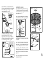
Step 4. Once the connection has been made,
the receiver inserts into the down rod hanging
bracket. The canopy comes up to cover the
receiver and bracket. (Fig. 11)
Figure 11
An additional safety support is provided to
prevent the fan from falling. Secure the
Support cable to the ceiling joist with screw
and washer. Screw and Support cable holder
lock the fixed Support cable. (Fig. 12)
Figure 12
Installing the canopy:
Step 1. Align the locking slots of the canopy
(C) with the two screws (FF) in the mounting
bracket (A). Push up to engage the slots and to
lock in place. (Fig. 13)
Step 2. Rotate the metal cover (D) clockwise
to lock in the bottom of the canopy. (Fig. 13)
Figure 13
Installing the Fan blades, rattan shade
and bulbs:
Step 1: Install the fan blades (M) onto the fan
motor shaft (U), Put the R-shaped pin (R) into
the motor shaft (U) to lock with a screwdriver
or pliers. (Fig. 15) Left handed thread on the
lock nut (Q).Install lock nut (Q) onto the motor
shaft (U) after the fan blades (M) is installed.
(Fig. 14)
Step 2. Screw light bulbs (F) into the fixture
Sockets(S). (Fig. 14)
Figure 14
Figure 15
6.

Installing the
battery
Install
12V
A23 battery (included),
To prevent
damage
to
transmitter, remove
the
battery
if not used for
long
periods.
(Fig. 16)
Figure 16
Restore power to ceiling fan and test for
proper
operation.
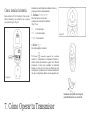
1. "○
,
○○
,
○○○
,
"buttons:
These three buttons are used
to set
the
fan
speed
as follows
(Fig. 17):
○=
Low
speed
○○ =
Medium
speed
○○○ =
High
speed
2. " " button:
This button turns the fan
off.
3.
The
" "
button turns
the
light ON
or
OFF and
also
controls the brightness setting. Press and release the
button to turn the light ON or OFF. Press and hold the
button
to set the
desired brightness. The light key has
an
auto-resume,
it will stay at the same brightness as the
last time
it
was turned
off.
Figure 17
7. Operating
Your
Transmitter
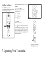
Installation of Transmitter Wall
Mount Holder with one screw.

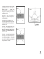
The Reverse switch is located on the top of the motor
housing. Slide the switch to the Left for warm weather
operation. Slide the switch to the Right for cool
weather operation. (Fig. 18)
NOTE: Wait for fan to stop before changing the
setting of the slide switch.
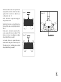
Speed settings for warm or cool weather depend on
factors such as the room size, ceiling height, number of
fans, etc.
Warm weather - (Forward) A downward air flow
creates a cooling effect as shown in Figure 19. This
allows you to set your air conditioner on a higher
setting without affecting your comfort.
Cool weather - (Reverse) An upward airflow moves
warm air off the ceiling area as shown in Figure 20.
This allows you to set your heating unit on a lower
setting without affecting your comfort.
Figure 1 9
Figure 2 0
Figure 18
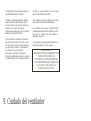
8.

Here are some suggestions to help you maintain
your fan
1.Because of the fan's natural movement,
some connections may become loose. Check
the support connections, brackets, and blade
attachments twice a year. Make sure they are
secure. (It is not necessary to remove fan from
ceiling.)
2.Clean your fan periodically to help maintain
its new appearance over the years. Use only a
soft brush or lint-free cloth to avoid scratching
the finish. The plating is sealed with a lacquer
to minimize discoloration or tarnishing. Do
not use water when cleaning. This could
damage the motor or possibly cause an
electrical shock.
3.Cover small scratches with a light application
of shoe polish.
4.There is no need to oil your fan. The motor has
permanently lubricated bearings.
5.The fan comes with a pre-assembled blade and
front guard for your easy installation. Check that
all screws are tight and securely in place.
6.Use a lint free lightly damp cloth or duster to
remove dust from the blades.
IMPORTANT
MAKE SURE THE POWER IS OFF AT THE
ELECTRICAL PANEL BOX BEFORE YOU
ATTEMPT ANY REPAIRS. REFER TO THE
SECTION "MAKING ELECTRICAL
CONNECTIONS"
9. Care of
Your
Fan

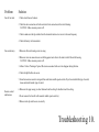
Problem
Fan will not start.
Fan sounds noisy.
Remote control
malfunction
Solution
1. Check circuit fuses or breakers.
2. Check line wire connections to the fan and switch wire connections in the switch housing.
CAUTION: Make sure main power is
off.
3. Check to make sure the dip switches from the transmitter and receiver are set to the same frequency.
4. Check the battery in the transmitter.
1. Make sure all motor housing screws are snug.
2. Make sure wire nut connections are not rubbing against each other or the interior wall of the switch housing.
CAUTION: Make sure main power is
off.
3. Allow a 24-hour "breaking-in" period. Most noise associated with a new fan disappear during this time.
4. Check that light bulb is also secure.
5. Some fan motors are sensitive to signals from solid-state variable speed controls. If you have installed this type of control,
choose and install another type of control.
6. Make sure the upper canopy is a short distance from the ceiling. It should not touch the ceiling.
1. Do not connect the fan with wall mounted variable speed control (s).
2. Make sure the dip switches are set correctly.
Troubleshooting 10.

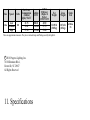
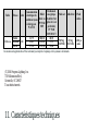
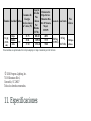
Size Speed Volts
Fan Power
Consumption
(without
lights) WATT
Airflow
CFM
Airflow
Efficiency
(Higher Is
Better)
CFM/WATT
Net
Weight Gross
Weight Cubic
Feet
14in.
Low
120
21.75 888.10 40.92 12.89 lb
(5.85kg)
18.74 lb
(8.5kg)
6.580cu.
Ft.
Medium 29.41 1109.82 37.75
High 37.10 1331.40 35.88
These are approximate measures. They do not include Amps and Wattage used by the light kit.
c2018 Progress Lighting, Inc.
701 Millennium Blvd.,
Greenville, SC 29607
All Rights Reserved
11. Specifications

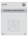
Manuel d’installation du ventilateur de plafond BELVA
93138712_B P250068

Garantie à vie limitée
Progress Lighting garantit à l’acheteur original que ses moteurs de ventilateur sont exempts de tout défaut de fabrication et de matériaux
pour aussi longtemps qu’il possède le ventilateur. Les interrupteurs à chaîne (tirette), les sélecteurs d’inversion, les condensateurs et les
finis en métal sont garantis exempts de tout défaut de matériaux ou de fabrication pendant une période d’un an à compter de la date
d’achat. La déformation des pales en bois ou plastique n’est pas couverte par la présente garantie, ni ne sont la corrosion ou toute
détérioration des finis pour les ventilateurs installés à moins de 16 km d’une côte. Les garanties prolongées couvrant les produits
homologués ENERGY STAR® peuvent s’appliquer.
Les ventilateurs de plafond de Progress Lighting avec sources de lumière à DEL intégrées, s’ils sont installés correctement et dans des
conditions normales d’utilisation, sont garantis contre les défauts de matériaux et de fabrication qui empêchent les sources de lumières de
fonctionner conformément aux spécifications pendant (i) cinq (5) ans à compter de la date d’achat pour les modules d’éclairage à DEL et
les composants électriques des ventilateurs utilisés dans les résidences unifamiliales et (ii) trois (3) ans à compter de la date d’achat pour
les modules d’éclairage à DEL et les composants électriques des ventilateurs utilisés dans les applications multifamiliales ou
commerciales. Les ampoules DEL fournies par Progress Lighting ne sont couvertes par aucune garantie autre que la garantie du fabricant.
Les ampoules non DEL ne sont couvertes par aucune garantie.
Date d’achat
Magasin d’achat
Modèle nº
Nº de série
L’acheteur original peut retourner le ventilateur défectueux au lieu d’achat avec une preuve d’achat pendant les 30 premiers jours pour
obtenir un remplacement. Au bout de 30 jours, l’acheteur original DOIT communiquer avec Progress Lighting au 864 678-1000 pour
réclamer une réparation ou un remplacement, selon la seule détermination de Progress Lighting et ceci constituera le seul et unique
recours de l’acheteur.
Nº de fournisseur 111041
Les frais de main d’œuvre et d’expédition sont exclus. La présente garantie ne couvre pas les coûts ou frais associés à la main d’œuvre (y
compris, sans s’y limiter, les honoraires de l’électricien) requise pour installer, retirer ou remplacer le ventilateur ou des pièces
quelconques du ventilateur.
La présente garantie ne s’applique pas à toute perte ou tout dommage résultant de (i) une usure ou altération normale, un mauvais usage,
un usage abusif ou la négligence, ou (ii) une installation, une utilisation, une réparation ou un entretien incorrect(e) par l’acheteur original
ou une tierce partie, y compris mais sans s’y limiter, une tension d’alimentation incorrecte ou une surtention, l’utilisation de pièces ou
accessoires inapproprié(e)s, une réparation non autorisée (effectuée ou tentée), ou un manque d’entretien du ventilateur.
LES GARANTIES CI-DESSUS ÉTABLISSENT L’OBLIGATION TOTALE DE PROGRESS LIGHTING ET LE SEUL ET UNIQUE
RECOURS DE L’ACHETEUR ORIGINAL EN VERTU DESDITES GARANTIES, CONCERNANT TELS PRODUITS. PROGRESS
LIGHTING N’EST PAS TENUE RESPONSABLE DES DOMMAGES (Y COMPRIS LES DOMMAGES INDIRECTS, SPÉCIAUX,
CONSÉCUTIFS OU ACCESSOIRES) RÉSULTANT D’UNE DÉFAILLANCE DU PRODUIT, EN RAISON D’UNE VIOLATION DE
GARANTIE, D’UNE RUPTURE DE CONTRAT OU AUTRE. LA PRÉSENTE GARANTIE REMPLACE TOUTES LES AUTRES
GARANTIES, EXPRESSES OU IMPLICITES, Y COMPRIS LES GARANTIES IMPLICITES DE QUALITÉ MARCHANDE ET
D’APTITUDE À UN USAGE PARTICULIER OU RELATIVES À L’ABSENCE DE CONTREFAÇON.
Certains états et provinces ne permettent pas les restrictions quant à la durée d’une garantie implicite, ni l’exclusion ou la restriction des
dommages indirects ou accessoires. Par conséquent, les restrictions et les exclusions mentionnées ci-dessus peuvent ne pas s’appliquer à
votre cas. En vertu de la présente garantie, vous bénéficiez de droits juridiques particuliers; toutefois, d’autres droits peuvent s’appliquer,
selon l’état ou la province où vous résidez.
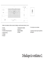
CUP

Règles de sécurité ............................................................................................................................................................. 1.
Déballage du ventilateur ................................................................................................................................................... 2.
Installation du ventilateur ................................................................................................................................................. 3.
Utilisation de l’émetteur ...................................................................................................................................................7.
Entretien du ventilateur ..................................................................................................................................................... 9.
Dépannage ....................................................................................................................................................................... 10.
Caractéristiques techniques ............................................................................................................................................. 11.
Table des matières

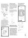
1. Pour réduire les risques de choc électrique, assurez-vous que le courant est
coupé au niveau de la boîte de disjoncteurs ou à fusibles avant de procéder à
l’installation.
2. Tout le câblage doit être conforme aux codes électriques locaux et au Code
électrique national. L’installation électrique doit être effectuée par un électricien
qualifié accrédité.
3. AVERTISSEMENT : Afin de réduire les risques de choc électrique et
d’incendie, n'utilisez pas ce ventilateur avec un dispositif de contrôle de la
vitesse du ventilateur à semi-conducteurs.
4. AVERTISSEMENT : Afin de réduire les risques d’incendie, de choc électrique
ou de blessure, installez sur une boîte de sortie de courant portant la mention
« Acceptable pour le support d’un ventilateur de 15,9 kg (35 lb) ou moins » et
utiliser les vis de montage fournies avec la boîte de sortie de courant. La plupart
des boîtes de sortie de courant couramment utilisées pour le support de
luminaires ne sont pas acceptables pour le support d’un ventilateur et peuvent
devoir être remplacées. Compte tenu de la complexité de l’installation de ce
ventilateur, il est fortement recommandé de faire appel à un électricien agréé
qualifié.
8. Pour éviter les blessures corporelles ou les dommages au ventilateur ou
d’autres objets, faites preuve de prudence en travaillant près du ventilateur ou
en le nettoyant.
9. N’utilisez ni eau ni détergents pour nettoyer le ventilateur ou les pales du
ventilateur. Un chiffon à poussière sec ou un linge légèrement humide
conviennent en général pour le nettoyage.
10. Après avoir effectué les branchements électriques, tournez les conducteurs
épissés vers le haut et insérez-les soigneusement dans la boîte de sortie de
courant. Les fils doivent être écartés de façon à ce que le conducteur mis à la
terre et le conducteur de mise à la terre de l’équipement soient du même côté
de la boîte de sortie de courant.
11. Les schémas électriques sont fournis à titre indicatif seulement. Les
luminaires qui ne sont pas emballés avec le ventilateur doivent être
homologués cUL et porter une mention spécifiant qu’ils peuvent être utilisés
avec ce type de ventilateur. Les interrupteurs doivent être homologués cUL
pour usage général. Se reporter aux instructions qui accompagnent les
luminaires.
5. La boîte de sortie de courant et la structure de support doivent être solidement
installées et en mesure de supporter de manière fiable un poids de 15,9 kg
(35 lb) ou moins. N’utiliser que des boîtes de sortie homologuées cUL et
portant la mention « POUR LE SUPPORT D’UN VENTILATEUR ».
6. Le ventilateur doit être installé en prévoyant un dégagement minimal de 3,05 m
(10 pi) entre le bas de la grille de protection du ventilateur et le plancher.
7. Ne placez pas d’objets dans la trajectoire des pales.
1. Règles de sécurité
AVERTISSEMENT
AFIN DE RÉDUIRE LE RISQUE DE BLESSURE, NE PLIEZ PAS LES BRAS DES PALES
(AUSSI APPELÉS SUPPORTS) PENDANT L’ASSEMBLAGE OU APRÈS L’INSTALLATION.
NE PLACEZ PAS D’OBJETS DANS LA TRAJECTOIRE DES PALES.
AVERTISSEMENT
AFIN DE RÉ
DUIRE LES RISQUES D’INCENDIE, DE CHOC ÉLECTRIQUE OU DE
BLESSURE, INSTALLER À UNE BOÎTE DE SORTIE DE COURANT PORTANT LA
MENTION ACCEPTABLE POUR LE SUPPORT DE VENTILATEUR.
REMARQUE
LISEZ ET CONSERVEZ TOUTES LES INSTRUCTIONS!

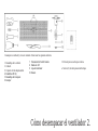
Déballez votre ventilateur et vérifiez le contenu de l’emballage. Les articles suivants devraient s’y trouver :
1. Monture
2. Couvercle
3. Ensemble boule/tige de suspension
4. Ampoules DEL (4)
5. Luminaire
6. Récepteur
7. Émetteur de télécommande
8. Pile de 12 V
9. Pale de ventilateur
10. Faîteau
11. Sac de pièces en vrac contenant :
a. Capuchons de connexion pour la quincaillerie
de montage (6)
Déballage du ventilateur 2.

Figure 2
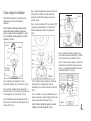
Outils requis
Tournevis cruciforme, tournevis à pointe plate, clé
réglable, escabeau et pince coupe-fils.
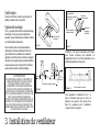
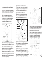
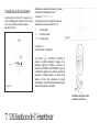
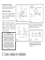
Options de montage
S’il n’y a pas de boîte de sortie de courant de montage
homologuée cUL en place, lisez les instructions
suivantes. Coupez l’alimentation en retirant les fusibles
ou en déclenchant les disjoncteurs.
Fixez la boîte de sortie de courant solidement et
directement à la structure du bâtiment. Utilisez les
pièces de fixation et les matériaux de construction
appropriés. La boîte de sortie de courant et son support
doivent pouvoir supporter le plein poids du ventilateur
en mouvement (au moins 15,9 kg [35 lb]). N’utilisez
pas de boîtes de sortie de courant en plastique.
Remarque : Une tige de suspension plus longue
peut s’avérer nécessaire pour maintenir un
dégagement correct, lors d’une installation sur un
plafond présentant une forte pente.
Pour suspendre le ventilateur là où il y a
déjà un luminaire mais pas de solive de
plafond, vous pourriez avoir besoin d’une
barre de suspension pour l’installation,
comme illustré à la Figure 4.
3. Installation du ventilateur
Figure 3
Boîte de sortie
de courant
Figure 1
AVERTISSEMENT
POUR RÉDUIRE LE RISQUE D’INCENDIE, DE
CHOC ÉLECTRIQUE OU DE TOUTE AUTRE
BLESSURE, FIXEZ LE VENTILATEUR
UNIQUEMENT À UNE BOÎTE DE SORTIE DE
COURANT CONÇUE POUR SUPPORTER UN
VENTILATEUR, AU MOYEN DES VIS FOURNIES
AVEC LA BOÎTE DE SORTIE DE COURANT. IL SE
PEUT QUE LES BOÎTES DE SORTIE DE
COURANT UTILISÉES COURAMMENT POUR LE
SUPPORT DE LUMINAIRES NE CONVIENNENT
PAS AUX VENTILATEURS ET DOIVENT ÊTRE
REMPLACÉES. EN CAS DE DOUTE, CONSULTEZ
UN ÉLECTRICIEN QUALIFIÉ.
Boîte de sortie de courant
Figure 4
Boîte de sortie de courant
Angle maximum
permis pour un plafond
en pente, 18,5
Boîte de sortie de
courant encastrée
Fournir un
support robuste
Support de
suspension
au plafond
La page est en cours de chargement...
La page est en cours de chargement...
La page est en cours de chargement...
La page est en cours de chargement...
La page est en cours de chargement...
La page est en cours de chargement...
La page est en cours de chargement...
La page est en cours de chargement...
La page est en cours de chargement...
La page est en cours de chargement...
La page est en cours de chargement...
La page est en cours de chargement...
La page est en cours de chargement...
La page est en cours de chargement...
La page est en cours de chargement...
La page est en cours de chargement...
La page est en cours de chargement...
La page est en cours de chargement...
La page est en cours de chargement...
La page est en cours de chargement...
La page est en cours de chargement...
La page est en cours de chargement...
-
 1
1
-
 2
2
-
 3
3
-
 4
4
-
 5
5
-
 6
6
-
 7
7
-
 8
8
-
 9
9
-
 10
10
-
 11
11
-
 12
12
-
 13
13
-
 14
14
-
 15
15
-
 16
16
-
 17
17
-
 18
18
-
 19
19
-
 20
20
-
 21
21
-
 22
22
-
 23
23
-
 24
24
-
 25
25
-
 26
26
-
 27
27
-
 28
28
-
 29
29
-
 30
30
-
 31
31
-
 32
32
-
 33
33
-
 34
34
-
 35
35
-
 36
36
-
 37
37
-
 38
38
-
 39
39
-
 40
40
-
 41
41
-
 42
42


Progress Lighting P250068-31M-WB Mode d'emploi
- Catégorie
- Ventilateurs ménagers
- Taper
- Mode d'emploi
- Ce manuel convient également à
dans d''autres langues
Documents connexes
-
Progress Lighting 93099650 B Guide d'installation
-
-
-
 PROGRESS LIGHTNING P250002-143-30 Mode d'emploi
-
Progress Lighting P250000-081 Guide d'installation
-
-
-
Progress Lighting P250012 Manuel utilisateur
-
-
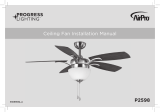 PROGRESS LIGHTNING AirPro P2598 Guide d'installation