
INSTALLATION
Grâce à sa taille réduite, le Module Multifonction Zigbee s’installe
dans une boîte de raccordement ou derrière un interrupteur, une
prise électrique, ou une sortie de câble.
nodon.fr section “support”
NodOn SAS
121 rue des Hêtres
45590 St CYR EN VAL
(FRANCE)
CONTACT SAV
MODE D’EMPLOIFR
Ajoutez le Module Multifonction Zigbee au
tableau électrique avec le Boitier Rail DIN*
NodOn. *Accessoire en option
NOTICE
DÉTAILLÉE
APPROBATIONS ET CERTIFICATIONS
PRÉCAUTIONS D’USAGES
• N’utilisez jamais l’appareil s’il n’est pas correctement
installé et placé à l’intérieur d’une boite de raccordement
conforme aux normes en vigueur.
• Tenez le produit éloigné de tous liquides.
DANGER D’ÉLECTROCUTION
AVANT T O U T E I N S TA L L AT ION ASSUREZ-
VOUS D’AVOIR COUPÉ L’ ALIMENTATION
ÉLECTRIQUE SOUS PEINE D’ÉLECTROCUTION.
Coupez directement l’alimentation depuis le coffret
électrique, pour éviter tout risque d’électrocution. Ce module
est conçu pour une utilisation sous tension, une mauvaise
installation peut entraîner un incendie ou un choc électrique.
Si vous ne vous sentez pas à l’aise avec les installations
électriques, veuillez consulter un professionnel.
Le module doit obligatoirement être installé ET connecté en
suivant scrupuleusement les instructions de cette notice.
Nous ne pourrons être tenus pour responsables en cas
d’accident ou de dommages dus au non respect des
instructions de montage.
Coupez l’alimentation avant toute intervention et n’effectuez
aucune modication si la LED est allumée.
MODULE MULTIFONCTION
Référence : SIN-2-1-01
Alimentation : 230V AC ~ 50Hz
Capacité de commutation : 230V AC - 10A // 30V DC - 10A
Consommation : <1W
Puissance Max. : 2300W (Charge résistive)
Liste des charges compatibles disponible sur nodon.fr/loads
Bande de fréquences radio utilisée : 868,0 à 868,6 Mhz
Puissance radio maximale : +3dBm
Portée : Jusqu’à 30m en intérieur
Température de fonctionnement : -10°C à 40°C
Indice de protection : IP 30
Appairage : jusqu’à 22 contrôleurs
EEP (Prol EnOcean) : D2-01-0F
Dimensions : 40 mm (l) x 44 mm (L) x 16.9 mm (h)
Poids : 34 g
Garantie : 2 ans
Accédez directement à la notice
détaillée sur la rubrique support
sur nodon.fr/support/
Ce produit est conforme au protocole radio EnOcean.
Ce produit est prévu pour être utilisé en intérieur
uniquement.
La présence de ce symbole sur un produit indique que ce
dernier est conforme à la directive européenne 2012/19/
UE. Renseignez-vous sur les dispositions en vigueur dans
votre région concernant la collecte séparée des appareils
électriques et électroniques. Respectez les réglementations locales
et ne jetez pas le produit avec les ordures ménagères ordinaires.
La mise au rebut correcte d’anciens produits permet de préserver
l’environnement et la santé.
Par la présente, NodOn SAS déclare que cet équipement
radio est conforme à la directive RED 2014/53/UE.
Le texte intégral de la déclaration de conformité
de l’UE est disponible à l’adresse Internet suivante : nodon.fr
section «Support»
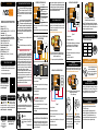
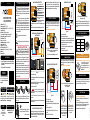
ENTRÉES / SORTIES DU MODULE
Chaque borne peut accepter un câble de 2.5 mm2 maximum
dénudé de 8mm.
NEntrée Neutre
LEntrée Phase
Entrée pour
l’interrupteur laire 1 (I1)*
Entrée pour
l’interrupteur laire 2 (I2)*
Borne d’entrée, le potentiel
transitera vers la borne
de sortie
Borne de sortie
*Interrupteur laire en option (voir rubrique schémas de câblage)
INSTALLATION - PORTAIL / PORTE DE GARAGE /
GÂCHE ÉLECTRIQUE
AUTO-DÉTECTION DU TYPE D’INTERRUPTEUR
Après avoir remis le courant, réalisez un appui sur le bouton de
votre interrupteur. Le module dispose d’un système d’auto-
détection qui détermine le type d’interrupteur laire (basculant
ou poussoir) câblé en entrée.
Note : La même configuration est appliquée pour les 2 entrées
(I1 et I2). Il n’est pas possible de combiner un interrupteur basculant
avec un interrupteur poussoir. Pour relancer l’autodétection, il est
nécessaire de réinitialiser manuellement le module multifonction
(voir procédure de réinitilalisation du module).
Figure 1
MODE COMMANDE D’ACCÈS
INSTALLATION - PRISE ÉLECTRIQUE
Figure 2
INSTALLATION - CHAUDIÈRE
Figure 3
APPAIRAGE
DU MODULE MULTIFONCTION
UTILISATION DU SOFT BUTTON
Le Soft Button fonctionnera comme suit :
PROCÉDURE DE RÉINITIALISATION
DU MODULE
Pour plus de détails sur l’appairage
avec une centrale domotique
et les autres produits compatibles,
veuillez consulter la rubrique
“Support” sur nodon.fr
DÉSAPPAIRAGE
DU MODULE MULTIFONCTION
APPAIRAGE
AVEC UNE CENTRALE DOMOTIQUE
INSTRUCCIONES
DE USO GEBRAUCHSANWEISUNG
Acceda directa-
mente a las
instrucciones detalladas
en la página de soporte de
nodon.fr/es/soporte/
Gehen Sie direkt zur
ausführlichen Anleitung
im Support Bereich unter
nodon.fr/de/technische-
unterstuetzung/
ON
ON
ON
Type d’appui Mode
Appui simple Inversion
Appui double ON
Appui long OFF
ASTUCE
1 Coupez le courant.
2 Démontez le poussoir qui pilote le portail/porte de garage/
gâche électrique.
3 Câblez le module multifonction, en parallèle du poussoir
selon le schéma gure 1.
4 Remettez le courant.
Attention : Activez le mode commande d’accès
(voir rubrique) avant l’appairage sous peine
d’endommager votre équipement.
5 Appairez le module multifonction, voir “Appairage du
module multifonction”.
6 Remontez le poussoir qui pilote le portail/porte de garage/
gâche électrique.
Il est impératif d’activer le mode commande d’accès avant
d’appairer votre télécommande/interrupteur pour piloter
votre portail/porte de garage/gâche électrique sous peine
d’endommager votre équipement.
Le module doit être raccordé et sous tension.
1 Effectuez 5 appuis consécutifs rapides sur le bouton
du module. La LED pulse en vert, conrmant l’activation
du mode commande d’accès.
2 Vous pouvez reprendre la procédure d’installation.
1 Coupez le courant.
2 Démontez la prise électrique.
3 Câblez le module multifonction selon le schéma gure 2.
4 Remettez le courant.
5 Appairez le module multifonction, voir “Appairage du
module multifonction”.
6 Remontez la prise électrique.
1 Coupez le courant.
2 Démontez la sortie de câble.
3 Câblez le module multifonction selon le schéma gure 3,
en prenant soin de raccorder les 2 ls de pilotage du
thermostat d’ambiance (voir notice de la chaudière).
4 Remettez le courant.
5 Suivez la procédure de mise en route selon votre type de
centrale domotique.
6 Remontez la sortie de câble.
Pour ajouter une télécommande/interrupteur/Soft Button
(compatible EnOcean) vous devez entrer en mode appairage.
Le module doit être raccordé et sous tension.
Vous disposez de 30
secondes pour appairer votre
contrôleur en effectuant un
appui court sur le bouton
de votre choix, celui-ci
pilotera votre portail/porte de
garage/gâche électrique
ou votre prise électrique.
1 Lancez l’appairage en effectuant 3 appuis consécutifs
rapides sur le bouton du module.
La LED scintille en rouge.
Note: Si la LED scintille orange pendant la procédure d’appairage,
cela signie que plus de 22 contrôleurs sont appairés et qu’aucun
autre contrôleur ne peut l’être. Vous devez donc supprimer un
contrôleur pour pouvoir en ajouter un nouveau.
3 La LED du module scintille 2 fois en vert,
conrmant l’appairage des deux appareils.
Vous disposez
de 30 secondes pour
appairer votre Soft Button
en effectuant 5 appuis
courts consécutifs sur votre
bouton.
Le module doit être raccordé et sous tension.
1 Appuyez plus de 5 secondes sur le bouton du module.
La LED scintille en orange.
2 Appuyez à nouveau sur le bouton (impulsion brève)
pour valider la réinitialisation. Si la réinitialisation se déroule
correctement, la LED clignote alternativement en rouge
et en vert, puis redevient verte. Recommencez si nécessaire.
3 Votre module a retrouvé sa conguration d’origine.
Effectuez la procédure identique à l’appairage (voir “appairage
du Module Multifonction”) en prenant soin d’appuyer sur le
bouton préalablement choisi pour contrôler votre portail/porte
de garage/gâche électrique ou votre prise électrique.

INSTALLATION
CONTACT AFTER SALES SERVICE
APPROVALS AND CERTIFICATIONS
MULTIFUNCTION
RELAY SWITCH
Reference: SIN-2-1-01
Power supply: 230V AC ~ 50Hz
Switching capabilities: 230V AC - 10A // 30V DC - 10A
Consumption: <1W
Max. Power: 2300W (Resistive load)
List of compatible loads available on nodon.fr/loads
Radio frequency range: 868.0 to 868.6 Mhz
RF power Max: +3dBm
Range: up to 30m indoor
Operational temperature: -10°C to 40°C
Protection rating: IP 30
Pairing: up to 22 controllers
EEP (EnOcean Prole): D2-01-0F
Dimensions: 40 mm (l) x 44 mm (L) x 16.9 mm (h)
Weight: 34 g
Warranty: 2 years
USE CAUTIONS
• Never use the device if it is not correctly installed and
placed inside a connecting box in conformity with the
current norms.
• Keep the product far away from liquids.
nodon.fr/en/ “support” section
NodOn SAS
121 rue des Hêtres
45590 St CYR EN VAL
(FRANCE)
This product is conform to EnOcean radio protocol.
This product must be used indoor only.
The presence of this symbol on a product indicates
that this one is conform to the European directive
2012/19/UE. Find out more about the provisions in
force in your region regarding the separate collection
of electrical and electronical devices. Respect the local rules and
do not throw out the product with common domestic wastes.
The correct rejection of ancient products allows to preserve the
environment and health.
Hereby, NodOn SAS declares that this radio equipment
is conform to the RED directive 2014/53/UE. The
integral text of the EU declaration of conformity
is available at the following online address: nodon.fr/en/
”support” section.
DANGER OF ELECTROCUTION
BEFORE ANY INSTALLATION MAKE SURE
THE POWER SUPPLY IS DISCONNECTED
TO AVOID ANY RISK OF ELECTROCUTION.
Directly cut the power supply from the breaker box to avoid
any risk of electrocution. This relay switch is designed to
be used power up, a wrong installation can create a re or
an electric shock. If you are not condent about electrical
installation, please ask a professional.
The relay switch must be installed and connected carefully
following the instructions of this user guide. We will not be
responsible for any loss or damage resulting from a non-
respect of the instructions of this user guide. Cut the power
supply before any operation and don’t do any modication
if the LED is still ON.
Thanks to its compact size, the Multifunction Relay Switch
can be installed behind a wall switch, an electrical outlet or
a cable outlet.
Add the Multifunction Relay Switch to the
electric panel with NodOn DIN Rail Box*.
*Optional accessory
RELAY SWITCH INPUT/OUTPUT
Each terminal can accept a cable of 2.5mm² maximum, stripped
of 8mm.
NTerminal for the Neutral
LTerminal for the Line
Input terminal for
the wired switch 1 (I1)*
Input terminal for
the wired switch 2 (I2)*
Input terminal, the potential
will pass through the output
terminal
Output terminal
*Wired switch optional (see the installation diagrams section).
USER GUIDEEN
INSTALLATION - GATE/GARAGE DOOR/
ELECTRIC LATCH
Figure 1
Figure 2
AUTO-DETECTION OF SWITCH TYPE
After turning the power supply ON, do a single push on the wired
wall switch. The relay switch has an auto-detection system to
automatically detect the type of wired wall switch (rocker or
push-button) wired at the input.
Note: The same conguration is applied for both inputs (I1 and
I2). It is not possible to combine a rocker switch with a push-
button. To perform a new auto-detection, the Multifunction Relay
Switch must be manually reset (see reset procedure).
CONTROL ACCESS MODE
INSTALLATION - ELECTRICAL OUTLET
INSTALLATION - BOILER
Figure 3
PAIRING PROCEDURE
USE OF YOUR SOFT BUTTON
The Soft Button will work as follows:
For more details on how to pair
a home automation gateway or
other compatible products, please
consult the “Support” section on
nodon.fr/en/
PAIRING
WITH A HOME AUTOMATION GATEWAY
UNPAIRING PROCEDURE
RESET PROCEDURE
SIN-2-1-01-UG-V3
DETAILED
USER GUIDE
Directly access the detailed user
guide on the Support section
on nodon.fr/en/technical-
support/
INSTRUCCIONES
DE USO GEBRAUCHSANWEISUNG
Acceda directa-
mente a las
instrucciones detalladas
en la página de soporte de
nodon.fr/es/soporte/
Gehen Sie direkt zur
ausführlichen Anleitung
im Support Bereich unter
nodon.fr/de/technische-
unterstuetzung/
ON
ON
ON
Types of press Action
Single press Reversal
Double press ON
Long press OFF
TIP
1 Cut the power supply.
2 Disassemble the push-button which controls the gate/garage
door/electric latch.
3 Wire the Multifunction Relay Switch, in parallel to the push-
button following the diagram gure 1.
4 Turn the power back ON.
Warning: Activate the control access mode (see the
section) before pairing to avoid any damage of your
equipment.
5 Pair the Multifunction Relay Switch, see “Pairing
procedure”.
6 Reassemble the push-button which controls the gate/garage
door/electric latch.
It is imperative to activate the control access mode
before pairing your remote/wall switch to control your
gate/garage door/electric latch to avoid damaging your
equipment.
Relay switch must be power supplied.
1 Do 5 brief presses on the button of the relay switch.
The LED pulses in green, conrming the activation
of the control access mode.
2 You can continue the installation procedure.
1 Cut the power supply.
2 Disassemble the electrical outlet.
3 Wire the Multifunction Relay Switch, following the diagram
gure 2.
4 Turn the power back ON.
5 Pair the Multifunction Relay Switch, see “Pairing
procedure”.
6 Reassemble the electrical outlet
1 Cut the power supply.
2 Disassemble the cable outlet.
3 Wire the Multifunction Relay Switch following the diagram
gure 3, making sure to connect the two wires which controls
the ambient thermostat (see your boiler user guide).
4 Turn the power back ON.
5 Follow the start-up procedure according to your home
automation gateway.
6 Reassemble the cable outlet.
To add a remote or a wall switch or the Soft Button (EnOcean
compatible) you must enter the pairing mode, your light must
be switched OFF.
Relay switch must be power supplied.
You have now 30
seconds to pair your controller
by briefly pressing on the
button of your choice, this one
will control your gate/garage
door/electric latch or your
electrical outlet.
1 Launch the pairing by doing 3 consecutive presses
on the relay switch button.
The LED blinks red.
You have now 30
seconds to pair your Soft
Button by doing 5 brief
consecutive presses on
the button.
Note: if the LED blinks orange during the pairing procedure, it
means that more than 22 controllers are paired and that no more
controller can be paired. You must remove one controller to add
a new one.
3 The relay switch LED will blink green twice,
conrming the pairing.
Do the same procedure as pairing (see “pairing procedure”) and
takes care of pressing the button chosen to control your gate/
garage door/electric latch or your electrical outlet.
Relay switch must be power supplied.
1 Press more than 5 seconds on your module’s button. The
LED blinks orange.
2 Press once again the button (short press) to conrm the
reset. If the reset is correct, the LED blinks alternatively in red
and green and stays green. Start again if necessary.
3 Your module has now its original settings.
-
 1
1
-
 2
2


