ESAB Origo™Feed 304 M13u Manuel utilisateur
- Catégorie
- Système de soudage
- Taper
- Manuel utilisateur
Ce manuel convient également à

US
FR
SA
Valid for serial no. 917-xxx-xxxx0461 284 031 US FR ES 20111122
Origo™ M13u
Feed 304
Manuel d'instructions
Instruction manual
Manual de instruções

- 2 -
Sous réserve de modifications sans avis préalable.
Rights reserved to alter specifications without notice.
Reservado el derecho de cambiar las especificaciones sin previo aviso.
AMERICAN 3. . . . . . . . . . . . . . . . . . . . . . . . . . . . . . . . . . . . . . . . . . . .
FRANÇAIS 21. . . . . . . . . . . . . . . . . . . . . . . . . . . . . . . . . . . . . . . . . . . . .
ESPAÑOL SA 36. . . . . . . . . . . . . . . . . . . . . . . . . . . . . . . . . . . . . . . . . .

AMERICAN
- 3 -
TOCa
Sous réserve de modifications sans avis préalable.
Rights reserved to alter specifications without notice.
1 USER RESPONSIBILITY 4. . . . . . . . . . . . . . . . . . . . . . . . . . . . . . . . . . . . . . . . . . . .
2 SAFETY PRECAUTIONS 4. . . . . . . . . . . . . . . . . . . . . . . . . . . . . . . . . . . . . . . . . . . .
3 SAFETY 8. . . . . . . . . . . . . . . . . . . . . . . . . . . . . . . . . . . . . . . . . . . . . . . . . . . . . . . . . . .
4 INTRODUCTION 10. . . . . . . . . . . . . . . . . . . . . . . . . . . . . . . . . . . . . . . . . . . . . . . . . . .
4.1 Equipment 10. . . . . . . . . . . . . . . . . . . . . . . . . . . . . . . . . . . . . . . . . . . . . . . . . . . . . . . . . . . . . . . .
5 TECHNICAL DATA 11. . . . . . . . . . . . . . . . . . . . . . . . . . . . . . . . . . . . . . . . . . . . . . . . .
6 INSTALLATION 12. . . . . . . . . . . . . . . . . . . . . . . . . . . . . . . . . . . . . . . . . . . . . . . . . . . .
6.1 Lifting instructions 12. . . . . . . . . . . . . . . . . . . . . . . . . . . . . . . . . . . . . . . . . . . . . . . . . . . . . . . . .
7 OPERATION 13. . . . . . . . . . . . . . . . . . . . . . . . . . . . . . . . . . . . . . . . . . . . . . . . . . . . . . .
7.1 Connections and control devices 16. . . . . . . . . . . . . . . . . . . . . . . . . . . . . . . . . . . . . . . . . . . .
7.2 Starting procedure 16. . . . . . . . . . . . . . . . . . . . . . . . . . . . . . . . . . . . . . . . . . . . . . . . . . . . . . . . .
7.3 Function explanations 16. . . . . . . . . . . . . . . . . . . . . . . . . . . . . . . . . . . . . . . . . . . . . . . . . . . . . .
7.4 Wire feed pressure 18. . . . . . . . . . . . . . . . . . . . . . . . . . . . . . . . . . . . . . . . . . . . . . . . . . . . . . . .
7.5 Changing / loading wire 18. . . . . . . . . . . . . . . . . . . . . . . . . . . . . . . . . . . . . . . . . . . . . . . . . . . .
7.6 Changing feed rollers 18. . . . . . . . . . . . . . . . . . . . . . . . . . . . . . . . . . . . . . . . . . . . . . . . . . . . . .
8 MAINTENANCE 19. . . . . . . . . . . . . . . . . . . . . . . . . . . . . . . . . . . . . . . . . . . . . . . . . . . .
8.1 Inspection and cleaning 19. . . . . . . . . . . . . . . . . . . . . . . . . . . . . . . . . . . . . . . . . . . . . . . . . . . .
9 ORDERING SPARE PARTS 20. . . . . . . . . . . . . . . . . . . . . . . . . . . . . . . . . . . . . . . . .
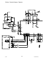
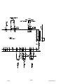
SCHEMATIC DIAGRAM 52. . . . . . . . . . . . . . . . . . . . . . . . . . . . . . . . . . . . . . . . . . . . . . . .
ORDERING NUMBER 54. . . . . . . . . . . . . . . . . . . . . . . . . . . . . . . . . . . . . . . . . . . . . . . . .
WEAR COMPONENTS 56. . . . . . . . . . . . . . . . . . . . . . . . . . . . . . . . . . . . . . . . . . . . . . . . .
ACCESSORIES 58. . . . . . . . . . . . . . . . . . . . . . . . . . . . . . . . . . . . . . . . . . . . . . . . . . . . . . .

- 4 -
US warninga
Be sure this information reaches the operator.
You can get extra copies through your supplier.
These INSTRUCTIONS are for experienced operators. If you are not fully familiar with the
principles of operation and safe practices for arc welding equipment, we urge you to read
our booklet, “Precations and Safe Practices for Arc, Cutting and Gouging, “Form 52-529.
Do NOT permit untrained persons to install, operate, or maintain this equipment. Do NOT
attempt to install or operate this equipment until you have read and fully understand these
instructions. If you do not fully understand these instructions, contact your supplier for
further information. Be sure to read the Safety Precautions before installing or operating
this equipment.
1 USER RESPONSIBILITY
This equipment will perform in conformity with the description thereof contained in this manual and
accompanying labels and/or insert when installed, operated, maintained and repaired in accordance
with the instruction provided. This equipment must be checked periodically. Malfunctioning or poorly
maintained equipment should not be used. Parts that are broken, missing, worn, distorted or
contaminated should be replaced immediately. Should such repair or replacement become necessary,
the manufacturer recommends that a telephone or written request for service advice be made to the
Authorized Distributor from whom it was purchased.
This equipment or any of its parts should not be altered without the prior written approval of the
manufacturer. The user of this equipment shall have the sole responsibility for any malfunction which
results from improper use, faulty maintenance, damage improper repair or alteration by anyone other
than the manufacturer or a service facility designated by the manufacturer.
2 SAFETY PRECAUTIONS
WARNING: These Safety Precautions are for your protection. They summarize precautionary
information from the references listed in Additional Safety Information section. Before performing any
installation or operating procedures, be sure to read and follow the safety precautions listed below as
well as all other manuals, material safety data sheets, labels, etc. Failure to observe Safety
Precautions can result in injury or death.
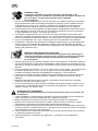
PROTECT YOURSELF AND OTHERS
Some welding, cutting and gouging precesses are noisy and require ear
protection. The arc, like the sun, emits ultraviolet (UV) and other radiation
and can injure skin and eyes. Hot metal can cause burns. Training in the
proper use of the processes and equipment is essential to prevent accidents.
Therefore:
1. Always wear safety glasses with side shields in any work area, even if welding helmets face
shields and goggles are also required.
US

- 5 -
US warninga
2. Use a face shield fitted with the correct filter and cover plates to protect your eyes, face, neck
and ears from sparks and rays of the arc when operating or observing operations. Warn
bystanders not to watch the arc and not to expose themselves to the rays of the electric-arc or
hot metal.
3. Wear flameproof gauntlet type gloves, heavy long-sleeve shirt, cuffless trousers, high-topped
shoes and a welding helmet or cap for protection, to protect against arc rays and hot sparks or
hot metal. A flameproof apron may also be desirable as protection against radiated heat and
sparks.
4. Hot sparks or metal can lodge in rolled up sleeves, trouser cuffs, or pockets. Sleeves and collars
should be kept buttoned and open pockets eliminated from the front of clothing.
5. Protect other personnel from arc rays and hot sparks with a suitable nonflammable partition or
curtains.
6. Use goggles over safety glasses when chipping slag or grinding. Chipped slag may be hot and
can fly far. Bystanders should also wear goggles over safety glasses.
FIRES AND EXPLOSIONS
Heat from flames and arcs can start fires. Hot slag or sparks can also cause
fires and explosions. Therefore:
1. Remove all combustible materials well away from the work area or cover the materials with a
protective nonflammable covering. Combusible materials include wood, clot, sawdust, liquid and
gas fuels, solvents, pants and coatings papper, etc.
2. Hot sparks or hot metal can fall through cracks or crevices in floors or wall openings and cause a
hidden smoldering fire or fires on the floor below. Make certain that such openings are protected
from hot sparks and metal.
3. Do not weld, cut or perform other hot work until the workpiece has been completely cleaned so
that there are no substances on the workpiece which might produce flammable or toxic vapors.
Do not do hot work on closed containers. They may explode.
4. Have fire extinguishing equipment handy for instant use, such as a garden hose, water pail, sand
bucket, or portable fire extinguisher. Be sure you are trained in its use.
5. Do not use equipment beyond its ratings. For example, overloaded welding cable can overheat
and create a fire hazard.
6. After completing operations, inspect the work area to make certain there are no hot sparks or hot
metal which could cause a later fire. Use fire watchers when necessary.
7. For additional information refer to NFPA Standard 51B, “Fire Prevention in Use of Cutting and
Welding Processes”, available from the National Fire Protection Association, Batterymarch Park,
Quincy, MA 02269.
ELECTRICAL SHOCK
Contact with live electrical parts and ground can cause severe injury or
death. DO NOT use AC welding current in damp areas, if movement is
confined, or if there is danger of falling. Therefore:
1. Be sure the power source frame (chassis) is connected to the ground system of the input power.
2. Connect the workpiece to a good electrical ground.
3. Connect the work cable to the workpiece. A poor or missing connection can expose you or others
to a fatal shock.
4. Use well-maintained equipment. Replace worn or damaged cables.
5. Keep everything dry, including clothing, work area, cables, torch/electrode holder and power
source.
6. Make sure that all parts of your bady are insulated from work and from ground.
7. Do not stand directly on metal or the earth while working in tight quarters or a damp area; stand
on dry boards or an insulating platform and wear rubber-soled shoes.
8. Put on dry, hole-free gloves before turning on the power.
9. Turn off the power before removing your gloves.
10. Refer to ANSI/ASC Standard Z49.1 (listed on next page) for specific grounding
recommendations. Do not mistake the work lead for a ground cable.
US

- 6 -
US warninga
ELECTRIC AND MAGNETIC FIELDS
May be dangerous. Electric current flowing through any conductor causes
localized Electric and Magnetic Fields (EMF). Welding and cutting current
creates EMF around welding cables and welding machines.
Therefore:
1. Welders having pacemakers should consult their physician before welding. EMF may interfere
with some pacemakers.
2. Exposure to EMF may have other health effects which are unknown.
3. Welders should use the following procedures to minimize exposure to EMF:
a. Route the electrode and work cables together. Secure them with tape when possible.
b. Never coil the torch or work cable around your body.
c. Do not place your body between the torch and work cables. Route cables on the same side
of your body.
d. Connect the work cable to the workpiece as close as possible to the area being welded.
e. Keep welding power source and cables as far away from your body as possible.
FUMES AND GASES
Fumes and gases, can cause discomfort or harm, particularly in confined
spaces. Do not breathe fumes and gases. Shielding gases can cause
asphyxiation.
Therfore:
1. Always provide adequate ventilation in the work area by natural or mechanical means. Do not
weld, cut or gouge on materials such as galvanized steel, stainless steel, cooper, zinc, lead
beryllium or cadmium unless positive mechanical ventilation is provided. Do not breathe fumes
from these materials.
2. Do not operate near degreasing and spraying operations. The heat or arc can react with
chlorinated hydrocarbon vapors to form phosgene, a highly toxic gas and other irritant gases.
3. If you develop momentary eye, nose or throat irritation while operating, this is an indication that
ventilation is not adequate. Stop work and take necessary steps to improve ventilation in the work
area. Do not continue to operate if physical discomfort persists.
4. Refer to ANSI/ASC Standard Z49.1 (see listing below) for specific ventilation recommendations.
5. WARNING: This product when used for welding or cutting, produces fumes or gases which
contain chemicals known to the State of Californa to cause birth defects and in some cases
cancer (California Health & Safety Code §25249.5 et seq.)
CYLINDER HANDLING
Cylinders, if mishandled, can rupture and violently release gas. Sudden
rupture of cylinder valve or relief device can injure or kill.
Therefore:
1. Use the proper gas for the process and use the proper pressure reducing regulator designed to
operate from the compressed gas cylinder. Do not use adaptors. Maintain hoses and fittings in
good condition. Follow manufacturer's operating instructions for mounting regulator to a
compressed gas cylinder.
2. Always secure cylinders in an upright position by chain or strap to suitable hand trucks,
undercarriages, benches, wall, post or racks. Never secure cylinders to work tables or fixtures
where they may become part of an electrical circuit.
3. When not in use, keep cylinder valves closed. Have valve protection cap in place if regulator is
not connected. Secure and move cylinders by using suitable hand trucks.
4. Locate cylinders away from heat, sparks and flames. Never strike an arc on a cylinder.
5. For additional information, refer to CGA Standard P-1, “Precations for Safe Handling of
Comporessed Gases in Cylinders”, which is available from Compressed Gas Association, 1235
Jefferson Davis Highway, Arlington, VA 22202.
US

- 7 -
US warninga
EQUIPMENT MAINTENANCE
Faulty or improperly maintained equipment can cause injury or death. Therefore:
1. Always have qualified personnel perform the installaion, troubleshooting and maintenance work.
Do not perform any electrical work unless you are qualified to perform such work.
2. Before performing any maintenance work inside a power source, disconnect the power source
from the incoming electrical power.
3. Maintain cables, grounding wire, connections, power cord and power supply in safe working
order. Do not operate any equipment in faulty condition.
4. Do not abuse any equipment or accessories. Keep equipment away from heat sources such as
furnaces, wet conditions such as water puddles, oil or grease, corrosive atmospheres and
inclement weather.
5. Keep all safety devices and cabinet covers in position and in good repair.
6. Use equipment only for its intended purpose. Do not modify it in any manner.
ADDITIONAL SAFETY INFORMATION
For more information on safe practices for electric arc welding and cutting equipment,
ask your supplier for a copy of “Precautions and Safe Practices for Arc Welding,
Cutting and Gouging”, Form 52-529.
The following publications, which are available from the American Welding Society, 550 N.W. LeJuene
Road, Miami, FL 33126, are recommended to you:
1. ANSI/ASC Z49.1 - “Safety in Welding and Cutting”
2. AWS C5.1 . “Recommended Practices for Plasma Arc Welding”
3. AWS C5.2 - “Recommended Practices for Plasma Arc Cutting“
4. AWS C5.3 - “Recommended Practices for Air Carbon, Arc Gouging and Cutting”
5. AWS C5.5 - “Recommended Practices for Gas Tungsten Arc Welding”
6. AWS C5.6 - “Recommended Practices for Gas Metal Arc welding”
7. AWS SP - “Safe practices” - Reprint, Welding Handbook
8. ANSI/AWS F4.1 - “Recommended Safe Practices for Welding and Cutting of Containers That
Have Held Hazardous Substances”
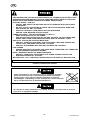
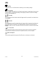
MEANING OF SYMBOLS
As used throughout this manual: Means Attention! Be Alert!
Means immediate hazards which, if not avoided, will result in
immediate, serious personal injury or loss of life.
Means potential hazards which could result in personal injury or loss
of life.
Means hazards which could result in minor personal injury.
US

© ESAB AB 2011
- 8 -
bm53da
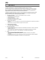
3 SAFETY
Users of ESAB welding equipment have the ultimate responsibility for ensuring that anyone who
works on or near the equipment observes all the relevant safety precautions. Safety precautions
must meet the requirements that apply to this type of welding equipment. The following recommen
dations should be observed in addition to the standard regulations that apply to the workplace.
All work must be carried out by trained personnel well-acquainted with the operation of the welding
equipment. Incorrect operation of the equipment may lead to hazardous situations which can result
in injury to the operator and damage to the equipment.
1. Anyone who uses the welding equipment must be familiar with:
S its operation
S location of emergency stops
S its function
S relevant safety precautions
S welding
2. The operator must ensure that:
S no unauthorized person is stationed within the working area of the equipment when it is
started up.
S no-one is unprotected when the arc is struck
3. The workplace must:
S be suitable for the purpose
S be free from drafts
4. Personal safety equipment
S Always wear recommended personal safety equipment, such as safety glasses, flame-proof
clothing, safety gloves.
S Do not wear loose-fitting items, such as scarves, bracelets, rings, etc., which could become
trapped or cause burns.
5. General precautions
S Make sure the ground cable is connected securely.
S Work on high voltage equipment may only be carried out by a qualified electrician.
S Appropriate fire extinquishing equipment must be clearly marked and close at hand.
S Lubrication and maintenance must not be carried out on the equipment during operation.
US

© ESAB AB 2011
- 9 -
bm53da
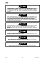
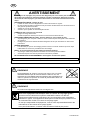
READ AND UNDERSTAND THE INSTRUCTION MANUAL BEFORE INSTALLING OR OPERATING.
ARC WELDING AND CUTTING CAN BE INJURIOUS TO YOURSELF AND OTHERS. TAKE
PRECAUSIONS WHEN WELDING. ASK FOR YOUR EMPLOYER'S SAFETY PRACTICES
WHICH SHOULD BE BASED ON MANUFACTURERS' HAZARD DATA.
ELECTRIC SHOCK - CAN KILL
S INSTALL AND EARTH THE WELDING UNIT IN ACCORDANCE WITH APPLICABLE
STANDARDS.
S DO NOT TOUCH LIVE ELECTRICAL PARTS OR ELECTRODES WITH BARE SKIN,
WET GLOVES OR WET CLOTHING.
S INSULATE YOURSELF FROM EARTH AND THE WORKPIECE.
S ENSURE YOUR WORKING STANCE IS SAFE.
FUMES AND GASES - CAN BE DANGEROUS TO HEALTH
S KEEP YOUR HEAD OUT OF THE FUMES.
S USE VENTILATION, EXTRACTION AT THE ARC, OR BOTH, TO TAKE FUMES AND
GASES AWAY FROM YOUR BREATHING ZONE AND THE GENERAL AREA.
ARC RAYS - CAN INJURE EYES AND BURN SKIN.
S PROTECT YOUR EYES AND BODY. USE THE CORRECT WELDING SCREEN AND
FILTER LENS AND WEAR PROTECTIVE CLOTHING.
S PROTECT BYSTANDERS WITH SUITABLE SCREENS OR CURTAINS.
FIRE HAZARD
S SPARKS (SPATTER) CAN CAUSE FIRE. MAKE SURE THEREFORE THAT THERE ARE
NO INFLAMMABLE MATERIALS NEARBY.
NOISE - EXCESSIVE NOISE CAN DAMAGE HEARING
S PROTECT YOUR EARS. USE EARMUFFS OR OTHER HEARING PROTECTION.
S WARN BYSTANDERS OF THE RISK.
MALFUNCTION - CALL FOR EXPERT ASSISTANCE IN THE EVENT OF MALFUNCTION.
PROTECT YOURSELF AND OTHERS!
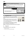
Class A equipment is not intended for use in residential locations
where the electrical power is provided by the public low-voltage
supply system. There may be potential difficulties in ensuring
electromagnic compatibility of class A equipment in those locations,
due to conducted as well as radiated disturbances.
This product is solely intended for arc welding. Any other use may result in personal
injury and / or equipment damage.
US

© ESAB AB 2011
- 10 -
bm53da
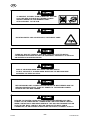
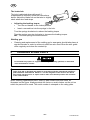
Dispose of electronic equipment at the recycling facility!
In observance of European Directive 2002/96/EC on Waste Electrical and Electronic
Equipment and its implementation in accordance with national law, electrical and/or
electronic equipment that has reached the end of its life must be disposed of at a
recycling facility.
As the person responsible for the equipment, it is your responsibility to obtain
information on approved collection stations.
For further information contact the nearest ESAB dealer.
Read and understand the instruction manual
before installing or operating.
ESAB can provide you with all necessary welding protection and accessories.
4 INTRODUCTION
The Feed 304 wire feed unit with control panel M13u is
intended for MIG/MAG-welding together with the infinitely
adjustable welding power sources MTS 3500i and 653
CC/CV.
The wire feed unit is sealed and contain four-wheel drive
wire feed mechanisms as well as control electronics.
It can be used together with wire on ESAB's MarathonPac,
or on wire spool (standard Ø 12”).
The wire feed unit can be installed either at the power
source, suspended above the workplace, on a support
arm or on the floor with or without wheel set.
ESAB's accessories for the product can be found on page 58.
4.1 Equipment
The Feed 304 wire feed unit is supplied with:
S Instruction manual
S Stickers with recommended wear parts
US

© ESAB AB 2011
- 11 -
bm53da
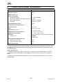
5 TECHNICAL DATA
Feed 304
Power supply 42 V 50 - 60 Hz
Power requirement 336 VA
Motor current I
max
8 A
Settings data
Wire feed speed
Burnback time
Creep start
2/4 stroke
75 - 985 Inches/Min
0 - 0.5 s
OFF or ON
2 stroke or 4 stroke
Gun connection EURO
Max. diameter wire spool 12”
Wire dimension .030 - 1/16”
Weight 25.4 lbs
Dimensions (l x w x h) 15” X 10.8” X 15.8”
Operating temperature 14 -104° F
Transportation temperature -4 - +131° F
Shielding gas
max pressure
All types intended for MIG/MAG welding
73 PSI (5 bar)
Permissible load at
60% duty cycle
630 A
Enclosure class IP2X *
Duty cycle
The duty cycle refers to the time as a percentage of a ten-minute period that you can weld at a cer
tain load without overloading. The duty cycle is valid for 104° F.
Enclosure class
The IP code indicates the enclosure class, i. e. the degree of protection against penetration by solid
objects or water. Apparatus marked IP 2X are intended for indoor use.
* IP23 is valid for optional wire spool cover art no 0458 674 880.
US

© ESAB AB 2011
- 12 -
bm53da
6 INSTALLATION
The installation must be done by a professional.
WHEN WELDING IN AN ENVIRONMENT WITH INCREASED ELECTRICAL DANGER,
ONLY POWER SOURCES INTENDED FOR THIS ENVIRONMENT MAY BE USED.
THESE POWER SOURCES ARE MARKED WITH THE SYMBOL
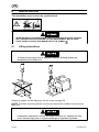
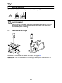
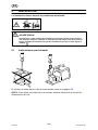
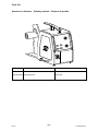
6.1 Lifting instructions
To avoid personal injury and / or equipment damage, lift using method and
attachment points shown here.
Ordering number for the lifting eye can be found on page 58.
NOTE! If another mounting device is used, this should be insulated from the wire
feed unit.
If equipment is placed on a surface that slopes more than 10°, toppling over may
occur. Personal injury and / or significant damage to equipment is possible
US

© ESAB AB 2011
- 13 -
bm53da
7 OPERATION
General safety regulations for the handling of the equipment can be found on
page 8. Read through before you start using the equipment!
A
H 0935
TO AVOID SHOCK, DO NOT TOUCH ELECTRODE WIRE OR PARTS IN
CONTACT WITH IT, OR UNINSULATED CABLE OR CONNECTIONS.
ASSURE THAT THE SIDE PANELS ARE CLOSED DURING OPERATION.
US

© ESAB AB 2011
- 14 -
bm53da
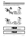
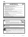
TO PREVENT THE REEL FROM SLIDING OFF THE HUB:
LOCK THE REEL IN PLACE BY TURNING THE RED
KNOB AS SHOWN ON THE WARNING LABEL
ATTACHED NEXT TO THE HUB.
ROTATING PARTS CAN CAUSE INJURY, TAKE GREAT CARE.
THERE IS A RISK OF TIPPING IF THE WIRE FEED UNIT IS FITTED WITH A
COUNTERBALANCE ARM. SECURE THE EQUIPMENT, ESPECIALLY IF USED ON
AN UNEVEN OR SLOPING SURFACE.
RISK OF CRUSHING WHEN REPLACING THE WIRE SPOOL!
DO NOT USE SAFETY GLOVES WHEN INSERTING THE WELDING WIRE
BETWEEN THE FEED ROLLERS..
BEFORE MAKING ANY CONNECTIONS BETWEEN THE WIRE FEEDER AND THE
WELDING POWER SOURCE, TURN OFF POWER TO THE WELDING POWER
SOURCE AND THE WIRE FEEDER.
BE SURE TO PROPERLY INSULATE THIS CONNECTION BEFORE APPLYING
POWER TO THE POWER SOURC. UNINSULATED CABLE AND PARTS CAN ARC
WHEN CONTACTING A GROUNDED SURFACE. THE ARC MAY DAMAGE EYES OR
START A FIRE. BODY CONTACT WITH AN UNINSULATED WELD CABLE
CONNECTOR, OR UNCOVERED CONDUCTOR CAN SHOCK, POSSIBLY FATALLY.
US

© ESAB AB 2011
- 15 -
bm53da
UNLESS STARTING TO WELD, DO NOT ALLOW THE WELDING WIRE TO TOUCH A
GROUNDED METAL SURFACE. THE WELDING WIRE BECOMES ELECTRICALLY
HOT WHEN THE SEDONDARY CONTACT IS CLOSED. KEEP FINGERS CLEAR OF
THE DRIVE ROLLS; THEY WILL START TURNING WHEN THE TORCH TRIGGER IS
PRESSED.
WHEN THE POWER SWITCH IS ON, AND TORCH TRIGGER IS DEPRESSED, THE
ELECTRODE WIRE BECOMES ELECTRICALLY HOT AND THE WIRE FEED ROLLS
ARE ACTIVATED. DO NOT TOUCH THE WIRE AS IT MAY CAUSE A POSSIBILY
FATAL SHOCK. UNLESS WELDING, DO NOT ALLOW WIRE TO TOUCH A
GROUNDED METAL SURFACE AS IT WILL CAUSE AN ARC FLASH. KEEP CLEAR
OF FEED ROLLS AND DRIVE GEARS.
PRIOR TO WELDING, IT IS IMPERATIVE THAT PROPER PROTECTIVE CLOTHING
(WELDING COAT AND GLOVES) AND EYE PROTECTION (GLASSES AND/OR
WELDING HELMET) BE PUT ON. FAILURE TO COMPLY MAY RESULT IN SERIOUS
INJURY.
FAILURE TO SHUT OFF SHIELD GAS IN A CONFINED SPACE MAY RESULT IN A
BUILD-UP OF FUMES, DISPLACING OXYGEN.
Do not terminate the arc by removing the torch from the weld area. Release the
torch trigger to stop welding before removing the torch.
When moving the equipment use intended handle. Never pull on the gun.
US

© ESAB AB 2011
- 16 -
bm53da
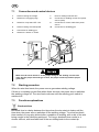
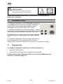
7.1 Connections and control devices
1 Knob for setting the voltage 7 Knob for setting burnback time
2 Switch for inching/gas purge 8 Connection for welding current from power
source (OKC)
3 Switch for creep start OFF / ON 9 Connection for control cable from power
source
4 Knob for setting wire feed speed 10 Connection for shielding gas
5 Connection for welding gun
6 Switch for 2-stroke / 4-stroke
Make sure the torch chosen is of the proper rating for the welding current to be
used, has the proper size and type of liner, the proper contact tip and the proper
guide tube.
7.2 Starting procedure
When the wire feed starts, the power source generates welding voltage.
If there is no welding current flow within three seconds, the power source switches
the welding voltage off. The wire feed continues until the welding gun's switch is
switched off.
7.3 Function explanations
Burnback time
Burnback time is a delay between the time when the wire starts to brake until the
time when the power source switches off the welding voltage. Too short burnback
time results in a long wire stickout after completion of welding, with a risk of the wire
being caught in the solidifying weld pool. Too long a burnback time results in a
shorter stickout, with increased risk of the arc striking back to the contact tip.
US

© ESAB AB 2011
- 17 -
bm53da
Inching
Used when wire is to be fed without switching on the welding voltage.
Gas purging
Used to measure the gas flow or to flush the gas hoses to clean them of any air and
moisture before commencing welding. Gas purging is carried out with the voltage
and wire feed switched off.
2 stroke
With 2 stroke, wire feed starts when the trigger switch is pressed in and ends when
it is released.
4 stroke
With 4 stroke, the gas flow starts when the trigger switch is pressed in and the wire
feed starts when it is released. The welding process continues until the switch is
pressed in again, the wire feed stops and when the switch is released the gas stops
flowing.
Creep start
Creep start means that the wire is fed at low speed until it comes into electrical
contact with the workpiece and then the speed increases to the set speed.
Wire feed speed
This sets the required feed speed of the filler wire in m/minute or in/minute.
US

© ESAB AB 2011
- 18 -
bm53da
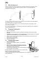
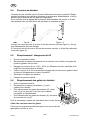
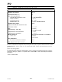
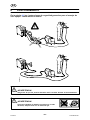
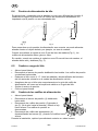
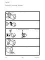
7.4 Wire feed pressure
Start by making sure that the wire moves smoothly through the wire guide. Then
set the pressure of the wire feeder's pressure rollers. It is important that the
pressure is not too great.
Fig 1 Fig 2
To check that the feed pressure is set correctly, you can feed out the wire against
an insolated object, e.g. a piece of wood.
When you hold the gun approx. 0.2” (5 mm) from the piece of wood (fig. 1) the
feed rollers should slip.
If you hold the gun approx. 2” (50 mm) from the piece of wood, the wire should be
fed out and bend (fig. 2).
7.5 Changing / loading wire
S Open the side panel.
S Disconnect the pressure sensor by folding it backwards, the pressure rollers
slide up.
S Straighten out the new wire 4 - 8”. File away burrs and sharp edges from the end
of the wire before inserting it into the wire feed unit.
S Make sure that the wire goes properly into the feed roller's track and into the
outlet nozzle or wire guide.
S Secure the pressure sensor.
S Close the side panel.
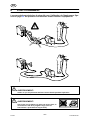
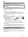
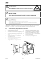
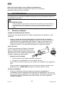
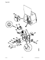
7.6 Changing feed rollers
S Open the side panel.
S Disconnect the pressure sensor (1) by folding it
backwards.
S Disconnect the pressure rollers (2) by turning the
axle (3) 1/4 turn clockwise and pulling out the axle.
The pressure rollers disconnect.
S Disconnect the feed rollers (4) by unscrewing the nuts
(5) and pulling out the rollers.
During installation, repeat the above in the reverse order.
Choice of tracks in the feed rollers
Turn the feed roller with the dimensioning mark for the required
track towards you.
US

© ESAB AB 2011
- 19 -
bm53da
8 MAINTENANCE
Regular maintenance is important for safe, reliable operation.
BE SURE THE BRANCH CIRCUIT OR MAIN DISCONNECT SWITCH IS OFF OR
ELECTRICAL INPUT CIRCUIT FUSES ARE REMOVED FROM THE POWER SOURCE
MAIN SUPPLY BEFORE ATTEMPTING ANY INSPECTION OR WORK ON THE
INSIDE OF THE WIRE FEEDER. PLACING THE POWER SWITCH ON THE WELDING
MACHINE IN THE OFF POSISION DOES NOT REMOVE ALL POWER FROM INSIDE
OF THE EQUIPMENT.
INSPECTION, TROUBLESHOOTING, AND REPAIR OF THIS EQUIPMENT SHOULD
BE UNDERTAKEN BY A COMPETENT INDIVIDUAL HAVING AT LEAST GENERAL
EXPERIENCE IN THE MAINTENANCE AND REPAIR OF SEMI-CONDUCTOR
ELECTRONIC EQUIPMENT. MAINTENANCE OR REPAIR SHOULD NOT BE
UNDERTAKEN BY ANYONE NOT HAVING SUCH QUALIFICATIONS.
Supplier warranty is void if customer attempts any work on product during the
warranty period.
8.1 Inspection and cleaning
IF UNINSULATED CABLE AND PARTS ARE NOT REPLACED, AN ARC CAUSED BY
A BARED CABLE OR PART TOUCHING A GROUNDED SURFACE MAY DAMAGE
UNPROTECTED EYES OR START A FIRE. BODY CONTACT WITH A BARED
CABLE, CONNECTOR, OR UNCOVERED CONDUCTOR CAN SHOCK, POSSIBLY
FATALLY.
Wire feed unit
Check regularly to insure that the wire feed unit is not clogged with dirt.
S Cleaning and replacement of the wire feed unit mechanism's worn parts should
take place at regular intervals in order to achieve trouble-free wire feed. Note
that if pre-tensioning is set too high, this can result in abnormal wear on the
pressure roller, feed roller and wire guide.
US

© ESAB AB 2011
- 20 -
bm53da
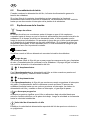
The brake hub
The hub is adjusted when delivered, if
readjustment is required, follow the instructions
below. Adjust the brake hub so that wire is slightly
slack when wire feed stops.
S Adjusting the braking torque:
S Turn the red handle to the locked position.
S Insert a screwdriver into the springs in the hub.
Turn the springs clockwise to reduce the braking torque
Turn the springs counter clockwise to increase the braking torque.
NB: Turn both springs the same amount.
Welding gun
S Cleaning and replacement of the welding gun's wear parts should take place at
regular intervals in order to achieve trouble-free wire feed. Blow the wire guide
clean regularly and clean the contact tip.
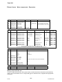
9 ORDERING SPARE PARTS
Do not make any repairs to equipment unless you are fully qualified, as described
in the maintenance section.
Origo Feed 304 is designed and tested in accordance with the international and Euro
pean standards 60974-5 and 60974-10 . It is the obligation of the service unit which
has carried out the service or repair work to make sure that the product still conforms
to the said standard.
When ordering replacement parts, order by part number and part name, as
illustrated on the figure. Always provide the series or serial number on the unit on
which the parts will be used. The serial number is stamped on the rating plate.
US
La page charge ...
La page charge ...
La page charge ...
La page charge ...
La page charge ...
La page charge ...
La page charge ...
La page charge ...
La page charge ...
La page charge ...
La page charge ...
La page charge ...
La page charge ...
La page charge ...
La page charge ...
La page charge ...
La page charge ...
La page charge ...
La page charge ...
La page charge ...
La page charge ...
La page charge ...
La page charge ...
La page charge ...
La page charge ...
La page charge ...
La page charge ...
La page charge ...
La page charge ...
La page charge ...
La page charge ...
La page charge ...
La page charge ...
La page charge ...
La page charge ...
La page charge ...
La page charge ...
La page charge ...
La page charge ...
La page charge ...
-
 1
1
-
 2
2
-
 3
3
-
 4
4
-
 5
5
-
 6
6
-
 7
7
-
 8
8
-
 9
9
-
 10
10
-
 11
11
-
 12
12
-
 13
13
-
 14
14
-
 15
15
-
 16
16
-
 17
17
-
 18
18
-
 19
19
-
 20
20
-
 21
21
-
 22
22
-
 23
23
-
 24
24
-
 25
25
-
 26
26
-
 27
27
-
 28
28
-
 29
29
-
 30
30
-
 31
31
-
 32
32
-
 33
33
-
 34
34
-
 35
35
-
 36
36
-
 37
37
-
 38
38
-
 39
39
-
 40
40
-
 41
41
-
 42
42
-
 43
43
-
 44
44
-
 45
45
-
 46
46
-
 47
47
-
 48
48
-
 49
49
-
 50
50
-
 51
51
-
 52
52
-
 53
53
-
 54
54
-
 55
55
-
 56
56
-
 57
57
-
 58
58
-
 59
59
-
 60
60


ESAB Origo™Feed 304 M13u Manuel utilisateur
- Catégorie
- Système de soudage
- Taper
- Manuel utilisateur
- Ce manuel convient également à
dans d''autres langues
Documents connexes
-
ESAB MultiPower 460 Pulse Control Panel Kit Mode d'emploi
-
-
-
ESAB Warrior™ Feed 304 Manuel utilisateur
-
-
-
ESAB PowerCut 700 PT-39 Manuel utilisateur
-
ESAB PowerCut 400 Manuel utilisateur
-
-
ESAB Mig 510 Origo™ Manuel utilisateur