La page est en cours de chargement...

Erklärung der
Bildsymbole
Das Blitzzeichen innerhalb eines
gleichseitigen Dreiecks warnt den
Benutzer vor nicht isolierter,
gefährlicher Spannung im Inneren
des Gerätes. Diese Spannung ist
hoch genug, um Personen durch
elektrischen Schlag zu gefährden.
Das Ausrufungszeichen innerhalb
eines gleichseitigen Dreiecks weist
den Benutzer auf wichtige
Bedienungs- und
Wartungsanweisungen hin, die in
den gerätebegleitenden Unterlagen
aufgeführt sind.
Explicación de
símbolos
El rayo dentro de un tríangulo
equilátero alerta al usuario de la
presencia de voltaje peligroso no
aislado dentro del producto, que
puede tener un nivel suficiente para
constitutuir un riesgo de descarga
eléctrica para el usario.
El signo de exclamación inscrito en
un triángulo equilátero alerta a los
usuarios de la presencia de
instrucciones importantes de
funcionamiento y mantenimiento
(servicio) en la literatura que
acompaña al producto.
Explanation of
graphical symbols
The lightning flash with arrowhead
symbol, within an equilateral
triangle, is intended to alert the user
to the presence of uninsulated
“dangerous voltage” within the
product’s enclosure that may be of
sufficient magnitude to constitute a
risk of electric shock to humans.
The exclamation point within an
equilateral triangle is intended to
alert the users to the presence of
important operating and
maintenance (servicing) instructions
in the literature accompanying the
product.
Explication des
symboles graphiques
Le symbole éclair avec pointe de
flèche à l'intérieur d'un triangle
équilatéral est utilisé pour alerter
l'utilisateur de la présence à
l'intérieur du coffret de "tension non-
isolée dangereuse" d'ampleur
suffisante pour constituer un risque
de choc électrique pour l'être
humain.
Le point d'exclamation à l'intérieur
d'un triangle équilatéral est employé
pour alerter les utilisateur de la
présence d'instructions importantes
pour le fonctionnement et l'entretien
(service) dans les documents
accompagnant l'appareil.
CAUTION: To reduce the risk of
electric shock, do not remove
the cover. No user-serviceable
parts inside. Refer servicing to
qualified service personnel.
WARNING: To prevent fire or
electric shock, do not expose
this equipment to rain or mois-
ture.
ATTENTION: Pour éviter les
risques de choc électrique, ne
pas enlever le couvercle. Cet
appareil ne comporte aucune
pièce pouvant être réparée par
l'utilisateur. Confier l'entretien
à un technicien qualifié.
AVERTISSEMENT: Pour éviter le
risque de choc électrique ou
d'incendie, n'exposez cet
appareil ni à l'humidité exces-
sive ni aux projections d'eau
(pluie, ruissellement, etc …)
VORSICHT: Um Gefährdung
durch elektrischen Schlag zu
vermeiden, darf das Gehäuse
nicht geöffnet werden. Es
befinden sich keine vom
Benutzer reparierbaren Teile im
Inneren des Gerätes. Über-
lassen Sie jegliche Reparatur
dem qualifizierten Fachmann.
WARNUNG: Um die Gefahr eines
Brandes bzw. eine Verletzung
durch elektrischen Schlag zu
vermeiden, sollten Sie das Gerät
niemals Regen oder Feuchtig-
keit aussetzen.
PRECAUCIÓN: Para reducir el
riesgo de alguna descarga
eléctrica, no quite la tapa. El
usario no debe ajustar los
componentes internos. Para
mantenimiento solicite la ayuda
de personal cualificado.
AVISO: Para evitar un incendio
o una descarga eléctrica, no
exponga este equipo a la lluvia
o humedad.
CAUTION
RISK OF ELECTRIC SHOCK
DO NOT OPEN
ATTENTION!
RISQUE DE CHOC ÉLECTRIQUE
NE PAS OUVRIR
VORSICHT
GEFAHR EINES ELEKTRISCHEN
SCHLAGES. NICHT ÖFFNEN!
PRECAUCIÓN
RIESGO DE DESCARGA ELÉCTRICA.
NO LO ABRA.
2

3
Safe operating levels ........................................... 26
Niveaux d'utilisation sécuritaires
Betriebspegel
Niveles adecuados de operación
APPLICATIONS ................................................. 27–29
APPLICATIONS
ANWENDUNGSBEISPIELE
APLICACIONES
TROUBLESHOOTING ....................................... 30–33
DÉPANNAGE
FEHLERBEHEBUNG
SOLUCIÓN DE PROBLEMAS
Problem:
no sound ........................................... 30-31
Problème:
pas de son
Problem:
kein Ton
Problema:
no hay sonido
Problem:
distorted sound .................................... 32
Problème:
son distortionné
Problem:
Verzerrungen
Problema:
sonido distorsionado
Problem:
no channel separation ....................... 32
Problème:
pas de séparation des canaux
Problem:
keine Kanaltrennung
Problema:
no hay separación entre los canales
Problem:
hum ......................................................... 33
Problème:
ronflement
Problem:
Brummen
Problema:
zumbidos
Problem:
hiss ......................................................... 33
Problème:
sifflement
Problem:
Rauschen/Zischen
Problema:
ruido (
hiss
)
Problem:
squeals and feedback ........................ 33
Problème:
bruits et effet Larsen
Problem:
Pfeifen und Rückkopplungen
Problema:
chillidos y retroalimentación
INNER WORKINGS ............................................ 34-35
SOUS LE CAPOT
INNERER AUFBAU
OPERACIÓN INTERNA
SPECIFICATIONS .............................................. 36–37
SPÉCIFICATIONS
TECHNISCHE DATEN
ESPECIFICACIONES
WARRANTY INFORMATION ................................. 38
INFORMATIONS DE GARANTIE
GARANTIE-BEDINGUNGEN
INFORMACIÓN DE GARANTÍA
ADDRESS & TELEPHONE INFORMATION ........... 39
ADRESSE POSTALE ET NUMÉROS
ADRESSE UND TELEFONNUMMERN
DIRECCIÓN Y TELÉFONO
Explanation of graphical symbols...................... 2
Explication des symboles graphiques
Erklärung der Bildsymbole
Explicación de símbolos
TABLE OF CONTENTS .............................................. 3
Table des matières
Inhaltsverzeichnis
Tabla de las materias
FCC Interference Statement ................................. 4
INTRODUCTION ........................................ 5–8
AVANT-PROPOS
EINFÜHRUNG
INTRODUCCIÓN
Front panel .................................................................7
Panneau avant
Vorderseite
Panel frontal
Rear panel ................................................................. 8
Panneau arrière
Rückseite
Panel posterior
FEATURES & SETUP............................... 9–15
CARACTÉRISTIQUES ET LEUR UTILISATION
AUSSTATTUNG & EINSTELLUNGEN
CARACTERÍSTICAS Y AJUSTES
Clip limiter ................................................................. 9
Limiteur d'écrêtement
Clip Limiter
Limitador de picos
Input filter ................................................................10
Filtres d'entrée
Eingangsfilter
Filtro de entrada
Parallel input mode................................................11
Mode entrées parallèles
Eingangsparallelschaltung
Modo de entradas paralelas
Bridge mono mode .......................................... 12-13
Mode ponté mono
Monobrückenbetrieb
Modo puenteado en mono
What are the differences among Stereo,
Parallel Input, and Bridge
Mono modes? .......................................... 14-15
Modes stéréo, parallèle et ponté, quelles sont
les différences?
Unterschiede zwischen Stereo-, Parallel- und
Monobrückenbetrieb
¿Cuáles son las diferencias entre los modos Estéreo,
Entradas Paralelas y Puenteado en Mono?
INSTALLATION ...................................... 16-17
INSTALLATION
EINBAU
INSTALACIÓN
CONNECTIONS ......................................18–22
CONNEXIONS
ANSCHLÜSSE
CONEXIONES
Inputs....................................................................... 18
Entrées
Eingänge
Entradas
Speakon™ outputs ............................................... 20
Sorties Speakon™
Speakon™ Ausgänge
Salidas Speakon™
Binding post outputs ............................................ 21
Bornes à écrou
Anschlussklemmen
Terminales con tornillo
Operating voltage (AC mains) ............................. 22
Tension d’utilisation (alimentation CA)
Netzanschluß
Voltaje de operación (CA principal)
DataPort .................................................................. 22
Port de données
DataPort
Puerto de datos
OPERATION ............................................23–26
UTILISATION
BETRIEB
OPERACIÓN
AC power switch .................................................. 23
Interrupteur d'alimentation CA
Netzschalter
Interruptor de encendido
LED indicators ....................................................... 23
Indicateurs DEL
LED-Anzeige
Indicadores LED
Gain controls ......................................................... 23
Contrôles de gain
Verstärkungsregler
Controles de ganancia
Security panel .................................................. 24-25
Panneau de securité
Sicherheitsabdeckung
Panel de seguridad
Fan cooling ............................................................ 26
Ventilation
Lüfterkühlung
Ventilación
TABLE OF CONTENTS • TABLE DES MATIÈRES • INHALTSVERZEICHNIS • TABLA DE LAS MATERIAS
3
La page est en cours de chargement...
La page est en cours de chargement...
La page est en cours de chargement...

7
Front panel
1. Power switch
2. Cooling vents
3. Gain control (1 per channel)
4.
CLIP
,
-10 dB
,
-20 dB
and
SIGNAL
indicator LEDs, 1 per
channel
5.
POWER
,
BRIDGE
, and
PARALLEL
indicator LEDs
6. Handles
Panel frontal
1. Interruptor de encendido
2. Rejillas de ventilación
3. Control de ganancia (1 por canal)
4. Indicadores LED para
CLIP
,
-10 dB
,
-20 dB
y
SIGNAL
(en
todos los canales)
5. Indicadores LED de
POWER
(encendido),
BRIDGE
(puenteado en mono) y
PARALLEL
(entradas paralelas)
6. Asas
Panneau avant
1. Commande marche/arrêt
2. Bouches de ventilation
3. Commande de gain (1 par canal)
4. DELs
CLIP
(écrêtage),
-10 dB
,
-20 dB
, et
SIGNAL
(tous les
canaux)
5. DELs
POWER
(alimentation),
BRIDGE
(mode mono ponté), et
PARALLEL
(entrées parallèles)
6. Poignées
Vorderseite
1. Netzschalter
2. Abluftöffnungen
3. Pegelsteller (1 pro Kanal)
4. LED-Anzeige für
CLIP
,
-10 dB
,
-20 dB
und
SIGNAL
(alle
Kanäle)
5. LED-Anzeige für
POWER
(Betrieb),
BRIDGE
(Mono-Brückenschaltung)
und
PARALLEL
(Eingangsparallelschaltung)
6. Griffe
INTRODUCTION
EINFÜHRUNG
INTRODUCCIÓNAVANT-PROPOS
POWERLIGHT 2 Front Panel
7

Rear panel
1. DataPort
2. Terminal block inputs
3. XLR inputs
4. TRS inputs
5. Configuration switch
6. Configuration switch chart
7. Speakon output, Channel 1
plus Channel 2 (4-wire)
8. Speakon output, Channel 2
9. Binding post outputs
10. Cooling air inlet vents
11. Serial number label
12. IEC connector for AC power cord
12a. Power cord retaining clip (install
on item 12)
Panneau arrière
1. DataPort (port de données)
2. Entrées sur blocs détachables
3. Entrées XLR
4. Entrées TRS
5. Sélecteur de configuration
6. Diagramme au sélecteur de
configuration
7. Sortie Speakon, Canal 1 plus
Canal 2 (4-fils)
8. Sortie Speakon (Canal 2)
9. Sorties sur bornes à écrou
10. Bouches de ventilation
11. Étiquette du numéro en série
12. Connecteur IEC pour cordon
d'alimentaion
12a.
Rückseite
1. DataPort
2. Euroblock (Phönix)
Anschlußstecker
3. XLR-Eingänge
4. Stereoklinken
5. Konfigurationsschalter
6. Erläuterung des
Konfigurationsschalters
7. Speakon-Ausgang, Kanal 1 mit
Kanal 2
8. Speakon-Ausgang (Kanal 2)
9. Anschlussklemmen
10. Lufteinlaßöffnung
11. Seriennummer
12. IEC Kaltgeräteanschluß
12a.
Panel posterior
1. DataPort (puerto de datos)
2. Entradas terminales de bloque
3. Entradas XLR
4. Entradas TRS
5. Selector de configuración
6. Esquema del selector de
configuración
7. Salida Speakon (canal 1 y
canal 2) (4 cables)
8. Salida Speakon (Canal 2)
9. Salidas de sujeción
10. Rejillas de ventilación
11. Etiqueta del número de serie
12. Conector IEC para cable de
poder CA
12a.
INTRODUCTION
EINFÜHRUNG
INTRODUCCIÓNAVANT-PROPOS
POWERLIGHT 2 Rear Panel
1
2
3
4
5
6
7
8
9
10
1
1
MODE SWITCH SETTINGS
TM
2
1
3
3
5
4
4
7
8
9
9
10
6
11
12
2
8

9
Clip limiter
DESCRIPTION
When the audio signal drives the
amp's output circuit beyond its power
capability, the amp clips and flattens
the peaks of the waveform. The clip
limiter detects this and quickly
reduces the gain to minimize the
amount of overdrive. To preserve as
much of the program dynamics as
possible, limiting occurs only during
actual clipping.
Each channel has its own clip limiter
that can be switched on or off
independently, as shown at left.
WHEN TO USE IT
When driving full-range speakers,
clip limiting reduces high frequency
distortion caused by bass overloads.
It also protects high frequency
drivers from excess overdrive and
harsh clipping harmonics.
We recommend using the clip
limiters in all applications.
FEATURES & SETUP CARACTERÍSTICAS
Y AJUSTES
Limitador de picos
DESCRIPCIÓN
Cuando la señal de audio estimula el
circuito de salida del amplificador más
allá de su capacidad de potencia se
satura con los picos de la forma de
onda. El limitador de picos detecta este
fenómeno y rápidamente reduce la
ganancia para minimizar la cantidad de
sobresaturación. Para conservar las
dinámicas del programa al máximo,
la limitación sólo ocurrira durante el
instante mismo de la saturación.
Cada canal tiene su propio limitador
de picos, usted los puede activar o
desactivar independientemente,
como se muestra a la izquierda.
¿CUÁNDO USARLO?
Cuando se usan bocinas de rango
completo, el limitador de picos reduce
la distorsión de las frecuencias agudas
causada por la sobrecarga de graves.
También protege a los drivers de fre-
cuencias agudas del exceso de satura-
ción y armónicos descontrolados.
CARACTÉRISTIQUES
ET LEUR UTILISATION
Limiteur d'écrêtement
DESCRIPTION
Quand le signal audio dépasse la
capacité de puissance du circuit de
sortie de l'amplificateur, le signal est
écrêté, tronquant les pointes de la
forme d'onde. Le circuit limiteur
d'écrêtement détecte cette condition
et réduit rapidement le gain de
l'amplificateur pour minimiser la
surtension. Afin de préserver le
maximum de la dynamique du signal,
le limiteur ne reste en fonction que
pour la durée de l'écrêtement.
Chaque canal est muni de son propre
limiteur, que vous pouvez activer et
désactiver indépendamment, tel
qu'illustré à gauche.
UTILISATION
Lors de l'utilisation de l'amplificateur
avec un signal plein registre, le circuit
limiteur réduit la distorsion des hautes
fréquences causée par les surtensions
des basses fréquences. Le circuit
protège aussi les haut-parleurs de
hautes fréquences des surtensions et
des harmoniques dues aux écrêtements.
Nous recommandons l'urilisation des
limiteurs pour toutes les applications.
AUSSTATTUNG &
EINSTELLUNGEN
Clip Limiter
BESCHREIBUNG
Wenn das Audiosignal die Ausgangs-
verstärker übersteuert, wird das Signal
geklippt, was zu einer Abflachung der
Wellenspitzen führt. Der Clip Limiter
(Spitzenbegrenzer) erkennt dies und
verringert schnell die Verstärkung um
die Stärke der Übersteuerung zu
reduzieren. Um dabei gleichzeitig aber
soviel Dynamik als möglich zu erhalten,
spricht der Spitzenbegrenzer nur
während echter Übersteuerungen an.
Jeder Kanal hat seinen eigenen Limiter,
der wahlweise zu- oder abgeschaltet
werden kann (siehe Zeichnung).
EINSATZ DES LIMITERS
Bei der Verwendung von Breitband-
Lautsprechersystemen reduziert der
Einsatz eines Spitzenbegrenzers die
Hochfrequenzverzerrungen, welche von
Übersteuerungen im Bassbereich ver-
ursacht werden. Außerdem werden die
Höhentreiber vor Übersteuerung und
hart geklippten Harmonischen geschützt.
Wir empfehlen die Verwendung
eines Spitzenbegrenzers für alle
applikationen.
CAUTION: Clip limiting reduces
extreme overdrive peaks,
allowing a higher average signal
level without audible distortion.
However, increasing the gain
with the clip limiter engaged, until
clipping is again audible, can
double the average output power.
Be careful not to exceed the
power rating of your speakers.
ATTENTION; le circuit de limiteur
d'écrêtement réduit les pointes
de surtension, augmentant le
niveau moyen du signal sans
distortion audible. On peut ainsi
facilement doubler la puissance
moyenne livrée aux haut-
parleurs. Il faut prendre soin
de ne pas excéder la puissance
admissible des haut-parleurs.
ACHTUNG: Der Einsatz eines
Spitzenbegrenzers ermöglicht
eine höheres Durchschnitts-
signal ohne hörbare Verzer-
rungen. Eine Erhöhung der
Verstärkung mit eingeschalt-
etem Clip Limiter kann die durch-
schnittliche Ausgangsleistung
auf das Doppelte erhöhen. Bitte
achten Sie daher darauf, die
Leistungsangaben Ihrer Laut-
sprecher nicht zu überschreiten.
ADVERTENCIA: El limitador de
picos reduce señales extremas
de saturación, permitiendo un
nivel de señal más alto sin
distorsión audible. Sin embargo,
aumentar la ganancia con el
limitador de picos activado
puede doblar la capacidad de
salida. Tenga cuidado de no
rebasar el límite de potencia
de sus bocinas.
Recomendamos usar los limitadores de
clip para todas las aplicaciones.
Clip Limiter Configuration
Switch Settings
9

Input filter
DESCRIPTION
The low-frequency (LF) filter rolls off
signals below either 30 Hz or 50 Hz.
This improves bass performance by
limiting sub-audio cone motion,
making more power available for the
speaker's rated frequency range.
The filter settings for each channel are
controlled individually through the DIP
switch settings shown. When the filter
is turned off, a 5 Hz rolloff protects
against DC or deep sub-audio inputs.
WHEN TO USE IT
As a rule, your speakers will sound
better with proper filtering. Unless
you already have filtering in a
preceding device, match the setting
to the low frequency rating of your
speakers. Vented (bass reflex,
ported, etc.) speakers are especially
sensitive to cone over-excursion at
frequencies below their rated limit.
The 50 Hz filter works well with most
compact full-range speakers. It has a
slight boost at 100 Hz for greater
fullness. The 30 Hz filter is intended for
woofers and large full-range
speakers. The "off" position should
be used only for subwoofer systems
capable of response below 30 Hz, or if
preceding devices such as crossovers
already provide adequate filtering.
FEATURES & SETUP
Filtro de entrada
DESCRIPCIÓN
El filtro de frecuencias graves (LF) le
permite atenuar señales abajo de los
30 Hz ó 50 Hz. Esto mejora el
rendimiento de las frecuencias graves
limitando una porción de audio no
audible que mueve el cono, dejando
más potencia disponible para el
rango de frecuencia de las bocinas.
Los ajustes del filtro para cada canal
se controlan individualmente con el
interruptor tipo DIP, como se describe.
Un atenuador de 5 Hz ofrece protección
contra DC o entradas de frecuencias
ultragraves cuando se apaga el filtro.
¿CUÁNDO USARLO?
Por regla, sus bocinas sonarán mejor
con el filtro apropiado. A menos que
anteriormente haya utilizado otro
aparato para filtrar y haya igualado las
frecuencias graves de sus bocinas. Las
bocinas con ventilación (como la bass
reflex, ported, etc …) son especial-
mente sensibles al desplazamiento
exagerado de los conos causado por
frecuencias por debajo de su límite.
Los filtros de 50 Hz funcionan bien con
la mayoría de bocinas compactas de
rango completo, como sistemas
suround. Tiene un pequeño aumento en
100 Hz para hacerlo mas completo.
El filtro de 30 Hz está pensado para
woofers y para bocinas de alto
rendimiento con rejillas. La posición
de apagado (off) debe ser usada
únicamente para sistemas de sub-
woofers capaces de una respuesta
inferior a los 30 Hz, o si procesadores
posteriores, como crossovers,
ofrecen filtros apropiados.
CARACTERÍSTICAS
Y AJUSTES
Filtres d'entrée
DESCRIPTION
Le filtre passe-haut, lorsqu'activé, réduit
le niveau de signal sous 30 Hz ou 50 Hz.
Ce filtre améliore la performance du
système en limitant le mouvement
excessif du cône du haut-parleur de
basses à des fréquences infrasoniques,
donnant plus de puissance
disponible dans le spectre audible.
Les ajustements des filtres pour chaque
canal se font séparément sur les
interrupteurs tel que montré ci-contre.
Lorsque les filtres sont désactivés, un
filtre passe-haut à 5 Hz entre en
fonction afin de protéger le haut-
parleur contre les tensions continues,
et contre les signaux infrasoniques.
UTILISATION
En règle générale, les haut-parleurs
fonctionnent mieux avec un filtre
bien ajusté. A moins que d'autres
équipements en amont dans la
chaîne soient munis de filtre, ajustez
le filtre de votre amplificateur en
accord avec votre haut-parleur. Les
enceintes à évent (bass reflex, etc)
sont particulièrement sensibles aux
surexcursion des cônes aux
fréquences inférieures à la
fréquence d'accord de l'enceinte.
Le filtre à 50 Hz fonctionne bien avec la
majorité des enceintes compactes, tel
les haut-parleurs de surround. Le filtre
fournit une légère hausse autour de
100 Hz, ce qui donne un son plus plein.
Le filtre à 30 Hz est conçu pour les
enceintes de basses et pour les haut-
parleurs principaux derrière l’écran. La
position “dérivation” ne devrait ètre
utilisée qu’avec des haut-parleurs
conçus pour reproduire les signaux
sous 30 Hz, ou encore si un autre
appareil dans a cha”ne est muni d’un
filtre adéquat.
CARACTÉRISTIQUES
ET LEUR UTILISATION
Eingangsfilter
BESCHREIBUNG
Ein LF- oder Hochpassfilter schneidet
Frequenzen unterhalb 30 Hz, bzw. 50 Hz
ab. Hierdurch wird die Basswieder-
gabe verbessert, da ultratiefe, störende
Frequenzen abgeschnitten werden, und
hierdurch mehr Leistung für die normale
Wiedergabe zur Verfügung steht.
Die Filtereinstellungen werden durch
den links abgebildeten DIP-Schalter
eingestellt. Bei abgeschaltetem Filter
werden die Frequenzen unterhalb
5 Hz unterdrückt, damit ein Schutz
von Gleichspannung und
Infraschallanteilen besteht.
EINSATZ DES EINGANGSFILTERS
In der Regel werden Ihre Lautsprecher
bei richtiger Filterung besser klingen.
Falls nicht schon an anderer Stelle eine
entsprechende Filterung stattgefunden
hat, stellen Sie die Filterung entsprech-
end dem Frequenzgang Ihrer Laut-
sprecher ein. Belüftete Lautsprecher
(z.B. Bassreflex, etc.) sind ausge-
sprochen empfindlich gegen zu große
Auslenkungen der Membran unterhalb
des spezifizierten Frequenzbereichs.
Der 50 Hz Hochpass arbeitet zufrieden-
stellend mit den meisten Breitband-
lautsprechern, wie sie in Surround-
systemeneingesetzt werden. Er weist
eine leichte Überhöhung bei 100 Hz
auf um einen klanglich volleren Eindruck
zu erzeugen. Das 30 Hz Filter ist für
Woofer und große Breitbandsysteme
gedacht. Die Schalterstellung “OFF”
sollte nur zusammen mit Subwoofer
Systemen verwendet werden, die
tiefere Frequenzen als 30 Hz
verarbeiten können, oder falls eine
entsprechende Filterung in den
vorgeschalteten Frequenzweichen
vorgenommen wurde.
AUSSTATTUNG &
EINSTELLUNGEN
100 20020 Hz 40040
80 1 kHz50050 30030 60
0 dB
-1
-2
-3
-4
-5
-6
+1
Ch. 1
Ch. 2
12345678910
LF OFF
12345678910
LF OFF
100 20020 Hz 40040
80 1 kHz50050 30030 60
0 dB
-1
-2
-3
-4
-5
-6
+1
Ch. 1
Ch. 2
30 HZ
LF ON
1234567891012345678910
30 HZ
LF ON
100 20020 Hz 40040
80 1 kHz50050 30030 60
0 dB
-1
-2
-3
-4
-5
-6
+1
Ch. 1
Ch. 2
1234567891012345678910
50 HZ
LF ON
50 HZ
LF ON
LF Filter Frequency Response- 50 Hertz filter on
LF Filter Frequency Response- 30 Hertz filter on
Input Filter Selection Switch Settings
LF Filter Frequency Response- filter off
10

11
FEATURES & SETUP
Modo de entradas paralelas
¿QUÉ ES?
El interruptor "Parallel Input" le permite
operar el amplificador en modo
paralelo, enviando la misma señal
hacia ambos canales sin necesidad
de utilizar un cable tipo "Y". Cada
canal controla su propia carga de
bocinas, con ganancia independiente,
filtros y limitador de picos.
Ajuste los selectores 4, 5 y 6 en la
posición de "ON", para acoplar las
entradas. Coloque los interruptores
en la posición de "OFF" para trabajar
en el modo estéreo, biamplificado, o
cualquier otro modo de 2 canales. El
indicador LED amarillo para el modo
PARALLEL
del panel frontal, le
advierte cuando el interruptor ha
sido ajustado en el modo paralelo.
CARACTERÍSTICAS
Y AJUSTES
Mode entrées parallèles
DESCRIPTION
Les interrupteurs "Parallel Inputs" vous
permettent d'utiliser l'amplificateur
en mode parallèle, où le même signal
est livré aux deux canaux sans avoir
à utiliser un câble "Y". Chaque canal
amplifie le signal indépendamment,
avec ajustements propres de gain,
de filtre, et de limiteur.
Ajustez les interrupteurs 4, 5, et 6 en
position "on" pour joindre les entrées des
deux canaux. Laissez les interrupteurs
en position "off" pour utilisation en
mode stéréo, bi-amplification, ou toute
autre application 2 canaux. La DEL
jaune
PARALLEL
sur le panneau avant
allume pour indiquer que l'amplificateur
est réglé en mode parallèle.
CARACTÉRISTIQUES
ET LEUR UTILISATION
AUSSTATTUNG &
EINSTELLUNGEN
Parallelbetrieb
BESCHREIBUNG
Durch die "Parallel Input" Schalter kann
der Verstärker parallel betrieben werden,
wobei das gleiche Signal beiden Kanälen
zugeführt wird. Jeder Verstärkerkanal
treibt dabei seinen eigenen Lautsprecher
mit unabhängiger Verstärkung,
Filterung und Spitzenbegrenzung.
Stellen Sie die Schalterpositionen 4,
5 und 6 auf "ON" um die Eingänge zu
verkoppeln. Schalten Sie die Schalter
aus für Stereo-, Bi-Amping- oder einen
anderen 2-Kanalbetrieb. Die gelbe
PARALLEL
-LED auf der Frontplatte
leuchtet auf, wenn Parallelbetrieb
gewählt wurde.
Mit parallelgeschalteten Eingängen
können die anderen Eingangsstecker
benutzt werden, um das Signal an
weitere Verstärker zu liefern.
1 SIGNAL —> 2 KANÄLE
Schalten Sie die Eingänge parallel,
wenn zwei Lautsprecher mit einem
Signal angefahren, und dabei aber
separate Verstärkung, Filterung oder
Begrenzung benutzt werden soll.
1 SEÑAL —> 2 CANALES
Utilice la entrada paralela cuando se
alimentan dos bocinas con una sola
señal de entrada (modo paralelo)
mientras se mantiene control por
separado de la ganancia, los filtros y
la limitación de ambos canales. Use
el modo "puenteado" en mono para
conectar la señal a amplificadores
adicionales por medio de los
conectores extra de entrada.
1 SIGNAL —> 2 CANAUX
Joignez les entrées (mode parallèle)
quand vous voulez contrôler deux
haut-parleurs avec des ajustements
spécifiques de gain, de filtre et de
limiteur à partir d'un même signal,
comme dans un système
ambiophonique (surround).
1 SIGNAL INTO 2 CHANNELS
Parallel the inputs when you need to
drive two amp channels with one
input signal
(parallel mode)
while
keeping separate control of both
channels' gain, filtering, and limiting.
Parallel input mode
DESCRIPTION
The "Parallel Input" switches let you
operate the amplifier in parallel
mode, delivering the same signal to
two channels without using a
Y-cable. Each channel drives its own
speaker load, with independent gain,
filtering, and clip limiting.
Set switch positions 4, 5, and 6
"ON"
to couple the inputs together.
Turn
the switches off for stereo,
bi-amping, or other 2-channel
modes.
The orange
PARALLEL
LED indicator on the front panel
warns you when the switches are set
to parallel.
Branching to other amps
In addition to parallel mode, you can
parallel the inputs in
bridged mono
mode
to carry the signal to additional
amplifiers through the unused extra
input jacks. This is often called a
"daisy-chain." See page 14 for an
explanation of amp operating
modes.
NOTE: If you're using a
balanced signal, use only
balanced patch cables; even
one unbalanced cable will
unbalance the entire signal
chain, possibly causing hum.
NOTE: Turn off the "Parallel
Inputs" switches when
feeding two separate signals
to the two channels.
"Daisy-Chaining" upper amplifier's input signal
to lower amplifier's input. Use one of the connection
methods shown (XLR, 1/4 "TRS or terminal block).
BITTE BEACHTEN SIE: Wenn Sie
ein symmetrisches Eingangssig-
nal anlegen, benutzen Sie auch
ausschließlich symmetrische
Kabel zur Weiterverbindung, da
auch nur ein einziges unsymmet-
risches Kabel das Gesamtsignal
unsymmetrisch werden läßt,
was möglicherweise Brummen
verursachen kann.
BITTE BEACHTEN SIE: Schalten
Sie den Parallelbetrieb aus,
wenn zwei separate Signale
eingespeist werden sollen.
NOTA: Si usa una señal balan-
ceada, utilice únicamente
cables adecuados. Un solo
cable no balanceado puede
afectar el recorrido de la
señal y producir zumbidos.
NOTA: Cuando alimente el
amplificador con dos señales
independientes, coloque el
interruptor "Parallel Inputs" en
la posición de apagado—"Off".
NOTE; désengager les inter-
rupteurs "parallel inputs"
quand vous amenez des signaux
différents aux deux canaux.
Mode Selection Switch Location and Settings
11

12
FEATURES & SETUP
Bridge mono mode
DESCRIPTION
Bridged mono mode combines the
power of both amplifier channels into
one speaker load, resulting in twice
the voltage swing, four times the
peak power, and approximately three
times the sustained power of a
single channel. This mode uses the
input, gain control, input filter, and
clip limiter of Channel 1; Channel 2's
filter and limiter have no effect.
The yellow
BRIDGE
LED on the
front panel indicates when the amp
is in bridged mono mode.
WHEN TO USE IT
Use bridged mono to deliver the power
of two channels to a
single
8- or
4-ohm load, such as a subwoofer.
Set switch position 7 to
BRIDGE
ON
. Use Channel 1's input, and
connect the speaker as shown.
Using the parallel inputs and bridge
mono together will illuminate both
the yellow
BRIDGE
and orange
PARALLEL
LEDs on the front panel.
Modo puenteado en mono
¿QUÉ ES?
El modo puenteado en mono combina
la potencia de dos canales de
amplificador (canales 1 y 2 y/ó 3 y 4 )
hacia una bocina, aumentando dos
veces el consumo de voltaje, cuatro
veces la potencia de picos y
aproximadamente tres veces la
potencia de sostenimiento de un solo
canal. Este modo utiliza la entrada, el
control de ganancia, filtro y limitador
del canal 1 (ó canal 3). Los controles del
canal 2 ó el 4 no producen ningún efecto.
El LED marcado BRIDGE en el panel
frontal, indica la posición del
amplificador en el modo
"puenteado" en mono.
CARACTERÍSTICAS
Y AJUSTES
Mode ponté mono
DESCRIPTION
Le mode ponté mono combine la
puissance de deux canaux de
l'amplificateur (canaux 1 et 2) pour
utilisation sur une seule charge de
hautparleur, doublant ainsi le
tension, quadruplant la puissance de
crête, et donnant environ trois fois la
puissance continue par rapport à un
canal simple. En mode ponté, utiliser
l'entrée, le contrôle de gain, le filtre
et le limiteur du canal 1, les contrôle
du canal 2 étant sans effet.
La DEL
BRIDGE
sur le panneau
avant allume pour indiquer que
l'amplificateur est réglé en mode
ponté mono.
UTILISATION
CARACTÉRISTIQUES
ET LEUR UTILISATION
AUSSTATTUNG &
EINSTELLUNGEN
Monobrückenbetrieb
BESCHREIBUNG
Monobrückenbetrieb vereint die
Leistung von zwei Verstärkerkanälen
(Kanal 1 & 2, und/oder 3 & 4) in eine
Lautsprecherlast, resultierend in
doppelter Verstärkerspannung,
vervierfachter Spitzenleistung, und
etwa verdreifachter Dauerleistung
eines einzelnen Kanals. Dieser
Modus benutzt den Eingang, den
Verstärkungsregler, den
Eingangsfilter und den Clip Limiter
von Kanal 1 oder Kanal 3. Die
entsprechenden Komponenten von
Kanal 2 und/oder Kanal 4 werden
nicht benutzt.
Die „BRIDGE"-LED auf der
Frontplatte leuchtet im
Monobrückenbetrieb auf.
Utilisez le mode ponté mono pour
amener la puissance de deux des
canaux sur une seule charge de 8 ou 4
ohms, tel un haut-parleur de sous-
graves. Ajustez l'interrupteur 7 en
position "on". Utilisez l'entrée du canal
1 et branchez la charge tel qu'indiqué
ci-contre.
ANWENDUNG
Sie benötigen diese Anwendung,
wenn Sie die Leistung von zwei
Kanälen auf eine einzelne 8- oder 4
Ohm Last geben wollen, z.B. auf
einen Subwoofer.
Schalter Nr. 7 auf Bridge Mode On.
Benutzen Sie den Eingang von
Kanal 1, und verbinden Sie den
Lautsprecher wie gezeigt.
¿CUÁNDO (O CUÁNDO NO)
USARLO?
Utilice el modo puenteado en mono
para pasar la potencia de dos
canales, a una sola carga de 8 ó 4
ohmios. Ajuste el selector número 7
en la posición "BRIDGE MONO ON".
Use las entradas del canal 1 y
conecte la bocina como se muestra
en la figura.
Setting DIP switch #7 for bridge mono operation
Setting DIP switches #4, 5 and 6 so that channel 1's
input is available for "daisy-chaining" on channel
2's input connectors.
12

FEATURES & SETUP
CARACTERÍSTICAS
Y AJUSTES
CARACTÉRISTIQUES
ET LEUR UTILISATION
AUSSTATTUNG &
EINSTELLUNGEN
Monobrückenbetrieb
(Fortsetzung)
Modo puenteado en
mono (continuación)
BRIDGED-MONO PRECAUTIONS:
This mode puts a high demand
on the amplifier and speaker.
Excessive clipping may cause
protective muting or speaker
damage. Ensure the speaker
has a sufficient power rating.
Output voltages greater than
100 volts rms are available
between the amplifier's
bridged terminals. CLASS 3
wiring methods, as specified
in accordance with national
(NEC) and local codes, must be
used to connect the speaker.
PRÉCAUTIONS EN MODE
MONO PONTÉ:
Le mode ponté mono place un
stress supplémentaire sur
l'amplificateur et le haut-parleur.
L'écrêtage excessif peut causer
la mise en sourdine par le
circuit de protection et/ou peut
endommager le haut-parleur.
Veuillez vous assurer que le
haut-parleur peut accepter la
puissance de l'amplificateur.
Des pointes de tension de plus
de 100 Vrms sont possibles
entre les bornes de sortie de
l'amplificateur en mode ponté
mono. Installez votre système
selon les codes électriques
local et national du site
d'installation.
Bridge mono mode
(continued)
Mode ponté mono
(suite)
BRÜCKENBETRIEB
VORSICHTSMAßNAHMEN:
Diese Betriebsart stellt hohe An-
forderungen an Verstärker und
Lautsprecher. Übermäßige Über-
steuerung kann zu Abschalten
des Verstärkers oder auch
Lautsprecherbeschädigungen
führen. Stellen Sie sicher, daß
der Lautsprecher entsprechende
Leistungen verarbeiten kann.
Ausgangsspannungen von mehr
als 100 Volt rms liegen zwischen
den Ausgangsanschlüssen an.
Daher müssen die einschlägigen
Sicherheitsmaßnahmen beim
Anschluß der Lautsprecher
beachtet werden.
PRECAUCIONES DEL MODO
PUENTEADO EN MONO
Este modo implica un gran
requerimiento para el amplifi-
cador y las bocinas. La
saturación excesiva puede
provocar un silencio para
proteger de cualquier daño a
la bocina. Asegúrese de que
ésta tenga el rango de
potencia necesario.
Los voltajes de salida mayores
a 100 voltios RMS están
disponibles entre las
terminales "puenteadas" del
amplificador. Los métodos de
conexión CLASS 3 (NEC), se
especifican de acuerdo a los
códigos locales o nacionales,
y deben utilizarse para
conectar la bocina.
Bridged mono output connection uses channel 1's Speakon only
• Mono ponté • Monobrückenbetrieb • Mono puente
Bridge mono operation- Binding post output connection uses
Ch.1 and Ch.2 "+" terminals.
BRIDGE MONO OUTPUT
CONNECTION-
Note that speaker connection for
bridge mono mode is different than
other modes. The illustrations to the
left show proper bridge mono
connections for both Speakon and
binding post connectors.
13

14
FEATURES & SETUP
What are the differences
among Stereo, Parallel
Input, and Bridge
Mono modes?
STEREO MODE
This is the "normal" way of using the
amplifier, in which each channel is
fully independent. Separate signals
connect at the inputs, the gain knobs
control their respective channels,
and separate speakers connect to
each output.
Examples:
• Two-channel (stereo) or multi-
channel playback.
• Bi-amp operation, with the low
frequencies in one channel and
the highs in the other.
PARALLEL INPUT MODE
This mode is just like Stereo mode,
except that the inputs for Channels 1
and 2 are internally connected
together. A signal into any input jack
will therefore drive both channels
directly. Each channel's gain control
and filter still functions
independantly, and each channel
feeds its own speaker load.
You can patch the input signal on to
additional amplifiers by using any of
the remaining input jacks.
Example:
• One program signal driving both
channels, with independent gain
control for each speaker system.
¿Cuáles son las diferen-
cias entre los modos
Estéreo, Entradas
Paralelas y Puenteado
en Mono?
MODO ESTÉREO
Esta es la manera "normal" de usar el
amplificador, donde cada canal
funciona independientemente. Con
señales separadas conectadas a las
entradas, botones de ganancia que
controlan su respectivo canal y
bocinas separadas conectadas a
cada salida.
Ejemplos:
• Reproducción multicanal o de dos
canales (estéreo)
• Operación bi-amplificada, con las
frecuencias graves por el canal 1
y las frecuencias agudas por el
canal 2 .
CARACTERÍSTICAS
Y AJUSTES
Modes stéréo, parallèle
et ponté, quelles sont
les différences?
MODE STÉRÉO
C'est la façon "normale" d'utiliser
l'amplificateur, où les des canaux sont
distincts. Des signaux différents peuvent
se trouver aux deux entrées, des
ajustements de gain, de filtre et de
limiteur sont possibles, et des haut-
parleurs distincts sont branchés aux
deux sorties.
Exemples:
• Réécoute deux canaux (stéréo) ou
canaux multiples
• Utilisation en mode bi-amplifié, avec
les basses fréquences amplifiées
par le canal 1 et les hautes par le
canal 2 . (recquiert l'utilisation
d'un séparateur de fréquences
électronique vendu séparément)
MODE PARALLÈLE
CARACTÉRISTIQUES
ET LEUR UTILISATION
AUSSTATTUNG &
EINSTELLUNGEN
Unterschiede zwischen
Stereo-, Parallel- und
Monobrücken-Betrieb
STEREOBETRIEB
Das ist die normale Betriebsart. Jeder
Kanal arbeitet unabhängig. Separate
Eingangssignalverbindungen, die
Verstärkungsregler werden für ihren
jeweiligen Kanal benutzt und separate
Lautsprecher werden an den Ausgangs-
verbindungen angeschlossen.
Beispiele:
• Zwei-Kanal- oder Stereo-, oder
Mehrkanal-Wiedergabe.
• Bi-Amp Betrieb: Tieffrequenter
Lautsprecher an Kanal 1,
hochfrequenter Lautsprecher an
Kanal 2.
Similaire au mode stéréo, sauf que
les entrées des canaux 1 et 2 sont
reliées à l'intérieur. Un signal amené
à l'une ou l'autre des entrées sera
donc amplifié par la paire de canaux.
Les contrôles de gain individuels
fonctionnent comme d'habitude, et
chaque canal alimente sa sortie de
haut-parleur.
Vous pouvez envoyer le signal vers
un autre amplificateur en vous
servant de la seconde entrée comme
sortie.
Exemple:
• Un seul signal d'ambiophonie
(surround) alimente les deux
canaux, avec contrôles de gain et
filtres indépendants pour chaque
systeme de haut-parleurs.
PARALLELBETRIEB
Wie Stereomodus, außer daß die
Eingänge von Kanal 1 und 2 intern
zusammengeschaltet sind. Ein Signal
in einen der Eingangsbuchsen wird
daher auf beide Kanäle gleichförmig
gegeben. Jeder der beiden
Verstärkerregler reagiert nach wie
vor separat und jeder Kanal liefert
separat Leistung an die
Lautsprecher.
Sie können das Eingangssignal an
weitere Verstärker weiterschleifen,
indem Sie einen der noch verfügbar
freien Eingangsbuchsen hierzu
benutzen.
Beispiel:
• Ein Surround-Kanal-Signal geht auf
beide Kanäle, mit unabhängigen
Verstärkungsreglern für jedes
Lautsprechersystem.
MODO DE ENTRADAS PARALELAS
Este modo es como el modo estéreo,
excepto por las entradas del canal 1 y
2 están unidas internamente. Una
señal conectada a cualquiera de las
entradas alimentará a ambos
canales directamente. Los controles de
ganancia de cada canal funcionarán
de una manera normal, y cada canal
lleva su propia carga para la bocina.
Usted puede conectar la señal de
entrada a otros amplificadores,
usando el conector que queda libre.
Ejemplo:
• Señal de canal surround
alimentando a los dos canales con
controles de ganancia
independientes para cada sistema
de bocinas.
14
Stereo, bi-amp, 2 channel mode
Parallel input mode

FEATURES & SETUP
BRIDGE MONO MODE
This mode combines the full power
capabilities of both channels into a
single speaker system. The amplifier
internally re-configures so that the
drive signal is applied to both
channels with the correct phase
relationship. This delivers double the
output voltage, resulting in four
times the peak power and three
times the sustained power into a
single 8- or 4-ohm speaker load. The
Bridge Mono mode section on pages
12 and 13 describes the special
speaker connection used.
Examples:
• Driving a single 8-ohm speaker
with the combined 4-ohm power
of two channels.
• Driving a single 4-ohm speaker
with the combined 2-ohm power
of both channels.
Precautions:
• Bridge Mono mode makes it
possible to drive thousands of
watts into a single speaker. AC
current consumption will usually
be higher. Avoid excessive signal
level, and make sure the wiring
and speaker can handle the
power.
• If the load is less than 4 ohms, or
prolonged overloads occur, the
amplifier will probably mute for
several seconds during peaks.
• Do not use 2-ohm loads.
MODO PUENTEADO EN MONO
Este modo combina la capacidad
total de potencia de ambos canales,
en un solo sistema de bocinas. El
amplificador se reconfigura
internamente de manera que ambos
canales operen como uno. Esto
produce el doble de voltaje de salida,
cuatro veces la potencia en picos y
tres veces la potencia de sosteni-
miento en cargas de 8 y 4 ohmios. La
sección del modo "Puenteado en
Mono" en la página 12-13 describe
la conexión usada para las bocinas.
LEA LAS PRECAUCIONES
ADICIONALES PARA EL MODO
DE PUENTEADO EN MONO EN
LA PÁGINA 12 y 13.
CARACTERÍSTICAS
Y AJUSTES
Ejemplos:
• Para alimentar una bocina de 8-
ohmios, con la potencia de dos
canales de 4-ohms.
• Para alimentar una bocina de 4-
ohmios, con la potencia de dos
canales de 2-ohms.
Precauciones:
• El modo de puenteado en mono
puede mandar miles de watts a
una sola bocina. El consumo de
corriente alterna (AC) también
será mayor. Evite niveles de
señales excesivos, y asegurese
que el cableado y las bocinas
resistan la potencia.
• Si la carga es menor a 4 ohms, ó
la saturación es muy frecuente, el
amplificador puede enmudecerse
(función Mute) durante los picos
por varios segundos.
• No use cargas de 2 ohmios.
MODE PONTÉ MONO
Ce mode combine la puissance des
deux canaux vers une seule sortie.
L'amplificateur est rebranché de
façon à ce que les deux canaux
fonctionnent en tant qu'unité. Ce
branchement double la tension de
sortie, ce qui multiplie par un facteur
de 4 la puissance en pointe et triple
la puissance en continu par rapport à
un canal simple dans un charge de 4
ou de 8 ohms. La section Mode
ponté mono en page 12-13 décrit les
branchements spéciaux des haut-
parleurs en ce mode.
Exemples:
• faire fonctionner un haut-parleur de
8 ohms avec la puissance combinée
à 4 ohms des deux canaux
• faire fonctionner un haut-parleur de
4 ohms avec la puissance combinée
à 2 ohms des deux canaux
Précautions:
• Le mode ponté mono permet
d'envoyer des milliers de watts de
puissance vers un seul haut-parleur.
La consommation de courant sera
plus élevée. S'assurer que le câblage
et le haut-parleur peuvent
supporter la puissance générée.
• Si la charge (haut-parleur) est de
moins de 4 ohms ou que des
surtensions prolongées se
produisent, il est possible que
l'amplificateur passe en mode
protection pour quelques
secondes lors de surtensions.
• Ne pas utiliser de charges de 2 ohms.
CARACTÉRISTIQUES
ET LEUR UTILISATION
VOIR LES INSTRUCTIONS
ADDITIONNELLES POUR
UTILISATION EN MODE PONTÉ
MONO EN PAGE 12-13.
AUSSTATTUNG &
EINSTELLUNGEN
MONOBRÜCKENBETRIEB
Diese Betriebsart addiert die volle
Verstärkung beider Kanäle für eine
einzelnes Lautsprechersystem. Der
Verstärker wird intern so umkonfiguriert,
so daß beide Kanäle wie ein einzelner
Kanal funktionieren. Hierdurch steht
ungefähr die doppelte Ausgangsspan-
nung, die vierfache Spitzenleistung
und ungefähr die dreifache Dauer-
leistung eines Einzelkanals in eine 8
oder 4 Ohm Last zur Verfügung.
Weitere Erläuterungen zur
besonderen Art des Anschlusses der
Lautsprecher finden Sie auf Seite 12
und 13.
Beispiele:
• Betrieb eines einzelnen 8 Ohm
Laut-sprecher mit der addierten 4
Ohm Leistung der zwei Kanäle
• Betrieb eines einzelnen 4 Ohm
Laut-sprecher mit der addierten 2
Ohm Leistung beider Kanäle
Vorsichtsmaßnahmen:
• Im Monobrückenbetrieb können
tausende Watt Leistung an einen
einzelnen Lautsprecher abgegeben
werden. Die Stromaufnahme des
Verstärkers wird höher als normal
sein. Vermeiden Sie daher über-
höhte Signalpegel und stellen Sie
sicher, daß die Verkabelung und
der Lautsprecher die hohe
Leistung verarbeiten können.
• Bei Lasten kleiner als 4 Ohm, oder
zu langen Übersteuerungen kann
der Verstärker für einige
Sekunden abschalten.
• 2 Ohm Lasten dürfen nicht
betrieben werden.
BITTE BEACHTEN SIE DIE
WARNHINWEISE AUF SEITE 12
UND 13.
SEE THE ADDITIONAL BRIDGE
MONO MODE WARNINGS ON
PAGES 12 AND 13.
Minimum bridge mono load on PL2 amplifiers is 4 ohms.
L'impedance de charge minimum au modèle PL2 en le mode ponté
mono est 4 ohms.
Minimale Lastimpedanz bei Monobrückenbetrieb der PL2 ist 4 Ohm.
La impedancia de carga mínima del amplificador PL2 en el modo
puenteado en mono es 4 ohmios.
15
Bridge mono mode with configuration switch set for "Stereo"
Bridge mono mode with configuration switch set for "Parallel Inputs"

16
INSTALLATION
Utiliser les quatre vis et rondelles de
montage pour fixer le devant de
l'amplificateur sur les rails de montage.
Il est recommandé de supporter
l'arrière de l'amplificateur, tout
particulièrement pour applications
mobiles et de tournée; des ensembles
de support sont disponibles du
service à la clientèle de QSC, ou en
commande spéciale chez votre
marchand ou distributeur local.
EINBAU
Benutzen Sie vier Befestigungs-
schrauben und Unterlegscheiben
zum Fronteinbau in das Rack.
Stützen Sie den Verstärker auch an
seiner Rückseite ab. Dies gilt besonders
für den mobilen Einsatz. Rückwärtige
Einbausätze können direkt bei QSC
oder den jeweiligen Händlern oder
Distributoren bestellt werden.
INSTALACIÓN
Utilice cuatro tornillos con rondanas
cuando coloque el amplificador en la
parte frontal del rack.
De la misma manera apoye la parte
posterior, especialmente cuando
vaya a transportar el equipo. Las
asas de montaje están disponibles
en el departamento de servicios
técnicos de QSC o pídalas
directamente a su distribuidor.
INSTALLATION
Use four screws and washers when
mounting the amplifier to the front
rack rails. Support the amplifier while
securing to the rails to avoid
distorting the front ears.
Supporting the amp at the rear is
important, especially for mobile and
touring use. Rear rack mounting ear
kits are available from QSC’s
technical services department or by
special order from your dealer or
distributor.
16
PL2 rack mounting installation
and major dimensions
PL2 dimensional information
La page est en cours de chargement...

or
ou
oder
ó
CONEXIONESCONNEXIONS ANSCHLÜSSE
EntradasEntrées
Chaque canal est muni de prises
XLR, ¼” (6.3 mm) et bloc détachable
“Euro-style” montés en parallèle,
avec branchement symétrique.
L’impédance d’entrée est de 12kOhm
en symétrique, et de 6kOhm en
branchement asymétrique.
Les signaux reçus en mode
symétrique sont moins sujets aux
ronflements dû aux interférences de
réseau électrique (hum), alors que les
branchements asymétriques peuvent
convenir pour les courtes distances.
L'impédance de sortie de la source
de signal devrait être de moins de
600 Ohm afin de réduire les pertes
en hautes fréquences avec de longs
câbles.
Eingänge
Jeder Kanal verfügt über electrisch
symmetrierte XLR Anschlüsse,
6,3 mm Stereo-Klinken und
Euroblock (Phönix) Anschlußstecker.
Die Eingangsim-pedanz beträgt
12 kOhm, symmetrisch und 6 kOhm
unsymmetrisch.
Symmetrische Signale verursachen
weniger Brummproblem, wobei
unsymmetrische Verbindungen
allerdings bei kurzen Kabelwegen
häufig ausreichen. Die
Quellimpedanz sollte dabei weniger
als 600 Ohm betragen, um einen
Höhenverlust bei längeren
Kabelwegen zu vermeiden.
Cada canal tiene una entrada activa
balanceada "Euro-style" tipo
terminal de bloque, XLR y TRS de 1/
4" (6.3mm) cableados en paralelo con
una impedancia de 12 kOhm
balanceada y 6 kOhm no
balanceada.
Las señales balanceadas son menos
propensas a inducir zumbidos debido
a la corriente alterna, pero para
cables cortos pueden usarse señales
no balanceadas. La impedancia de
salida debe ser menor de 600 ohms
para prevenir la pérdida de
frecuencias agudas en cables largos.
Inputs
Each channel has active balanced
"Euro-style" terminal block, XLR and
¼-inch (6.3 mm) TRS jacks wired in
parallel. The input impedance is
12 kOhm balanced or 6 kOhm
unbalanced. Each channel's three
input jacks are wired in parallel.
Unused input jacks may be daisy-
chained to additional amplifiers if
desired.
Balanced connection is
recommended. Balanced signals are
less prone to AC hum, but
unbalanced signals can be suitable
for short cable runs. The signal
source's output impedance should
be less than 600 Ohms to avoid high
frequency loss in long cables.
or
ou
oder
ó
Balanced inputs: Use the XLR, ¼-
inch (6.3 mm) TRS input jacks, or the
detachable terminal blocks.
Proper connection for all three
balanced input options are shown at
left.
Terminal block balanced • bloc détachable
symêtrique • symetrische Anschlußstecker
• Entrada de bloque balanceado
Use one of the three input connection options
1/4-inch (6.3mm) TRS and XLR connection
•Balanced•Symétrique•Symmetrisch•Balanceado
Entrées symétriques: Utiliser la
prise XLR, ¼” (6.3 mm) ou le bloc
détachable “Euro-style.”
Symmetrische Eingänge: Ver-
wenden Sie die XLR oder 6,3mm
Stereoklinkenbuchsen, oder die
Anschlußstecker.
Entradas balanceadas: Use las
entradas XLR o TRS de ¼ pulgada
(6.3 mm), o la terminal de bloque
modular.
shield
inverting
non-inverting
shield
CONNECTIONS
18

19
XLR unbalanced • XLR asymêtrique • unsymetrische XLR •
XLR no balanceado
TRS unbalanced • TRS
asymêtrique • unsyme-
trische Stereoklinke • TRS
no balanceado
Inputs (continued)
Unbalanced inputs: Connect the
unused side of the balanced input to
ground, as shown at left. A tip-sleeve
¼-inch (6.3 mm) connector will
correctly terminate the unused side
of the input without modification.
For two-channel (stereo) operation,
use the inputs for both Channel 1 and
Channel 2; for parallel or bridged
mono operation, use only the
Channel 1 input. See the section on
operating modes for more explanation.
To patch the audio signal to other
amps (parallel and bridged modes
only), see the instructions for using
parallel inputs on page 11.
CONNECTIONS CONEXIONESCONNEXIONS ANSCHLÜSSE
Entradas (continuado)
Entradas no balanceadas:
Conecte el lado libre de la salida
balanceada a tierra, como se muestra
a la izquierda. Con un conector tipo
tip-sleeve de ¼" (6.3mm) se llevará a
cabo la terminación apropiada del
conductor sin usar de la entrada sin
ninguna modificación.
Para operación en dos canales
(estéreo), use las entradas de los
canales 1 y 2. Para operación en
paralelo o puenteada en mono, use
la entrada del canal 1. Lea la sección
de los modos de operación para una
explicación más detallada. Para
enviar la señal de audio a otros
amplificadores (sólo en los modos
paralelo o puenteado en mono), lea
las instrucciones para entradas
paralelas en la página 11.
Eingänge (Fortsetzung)
Unsymmetrische Eingänge:
Verbinden Sie den ungenutzten Pin
des symmetrischen Steckers mit
Masse (siehe Abbildung). Bei einem
Mono-Klinkenstecker ist keine
Änderung nötig.
Im 2-Kanalbetrieb (Stereo), verwenden
Sie bitte beide Eingänge; im
Parallel-, bzw. Monobrückenbetrieb
verwenden Sie nur Eingang 1. Bitte
beachten sie die jeweiligen
Beschreibungen der ver-schiedenen
Betriebszustände. Um das Signal an
weitere Verstärker zu leiten (nur im
Parallel-, bzw. Monobrücken-
betrieb), beachten Sie bitte die
Beschreibungen auf Seite 11.
Entrées (suite)
Entrées asymétriques:
Connectez le côté non-utilisé de
l'entrée symétrique au châssis, tel
qu'illustré ci-contre. Une fiche ¼" (6.3
mm) mono (Tip Sleeve) fermera le
circuit sans modification.
En utilisation deux canaux (stéréo),
utilisez les prises des canaux 1 et 2;
en mode parallèle ou ponté mono,
utilisez la prise du canal 1. Voir les
explications dans les sections
appropriées du présent manuel. Pour
relier le signal audio de cet
amplificateur vers d'autres
amplificateurs (mode parallèle et
ponté mono seulement), voyez les
instructions en page 11.
jumper
jumper
1/4-inch (6.3mm) phone plug connection
•Unbalanced•Asymétrique•Unsymmetrisch•No Balanceado
Terminal block unbalanced •
bloc détachable asymêtrique •
unsymetrische Anschlußstecker
• Entrada de bloque no
balanceado
shield and
inverting
non-inverting
shield
jumper from
— to shield
19

2 channels/canaux/Kanäle/canales & 2 Speakons
(Stereo, bi-amp, or parallel mode; Modes stéreo, bi-amp ou parallèle; Stereo-, Bi-
amp- oder Parallelbetrieb; Modos estéreo, bi-amp o paralelo)
2 channels/canaux/Kanäle/canales & 1 Speakon
(Stereo, bi-amp, or parallel mode; Modes stéreo, bi-amp ou parallèle; Stereo-, Bi-
Amp- oder Parallelbetrieb; Modos estéreo, bi-amp o paralelo)
Bridged mono • Mono ponté • Monobrückenbetrieb • Mono puente
CONNECTIONS CONEXIONESCONNEXIONS ANSCHLÜSSE
CÂBLAGE DU HAUT-PARLEUR
Les câbles de fort calibres et les courtes
distances minimisent à la fois les pertes
de puissance et la dégradation du
coefficient d'amortissement. Evitez
de placer les câbles de haut-parleurs
à proximité des câbles d'entrée.
CABLEADO DE BOCINAS
Los cables gruesos y los trayectos cortos
minimizan la pérdida de potencia y
degradación por el factor de amorti-
guación. No coloque los cables de las
bocinas cercanos a los de entrada.
Para facilitar la inserción de los
conectores, le recomendamos que
use los nuevos conectores Speakon
NL4FC con retén.
Sorties Speakon™
Les amplificateurs de série PL2 vous
offrent un choix de connexion de
sortie: deux prises Speakon et des
bornes à écrou.
Les prises Speakon sont conçues
spécifiquement pour la connexion de
haut-parleurs de haute puissance. Elles
verrouillent en place, préviennent les
risques de choc électrique, et assurent
le branchement avec polarité correcte.
La prise Speakon du haut porte les
signaux de sortie des deux canaux, elle
est donc très utile lors de branchement
en modes parallèle, bi-amplifié, ou
ponté mono (voir les instructions et
précautions à suivre pour le branchement
en mode ponté mono en page 13). La
prise du bas ne porte que le signal du
canal 2. Voir les illustrations ci-contre.
Pour insertion plus facile, utiliser la
nouvelle génération des Speakon
NL4FC avec loquet à ressort.
Speakon™ Ausgänge
Die verstärker der PL2-Serie bieten
zwei verschiedene
Ausgangsanschlüsse: zwei Neutrik
NL4MD Speakonstecker und
anschlussklemmen.
Der Speakonanschluß wurde speziell
für den Anschluß von Hochleistungs-
lautsprechern konzipiert. Er rastet
ein, verhindert elektrischen Schlag
und sorgt für die richtige Polarität.
Die obere Speakonbuchse enthält
beide Kanäle, so daß sie besonders für
Parallel-, Biamp- oder Monobrücken-
betrieb geeignet ist (bitte beachten
Sie die Vorsichtsmaßnahmen wie
auf Seite 13 beschrieben). Die
andere Speakonbuchse enthält nur
die Signale von Kanal 2 (siehe auch
nebenstehende Zeichnung).
LAUTSPRECHERKABEL
Dickere und kürzere Kabel verringern
sowohl Leistungsverlust wie eine Ver-
schlechterung des Dämpfungsfaktors.
Verlegen Sie keine Ausgangskabel
neben den Eingangskabeln.
Salidas Speakon™
Los amplificadores PL2 ofrecen
diferentes opciones para conexiones
de salida: dos conectores Speakon
NL4MD de Neutrik y por medio de
las terminales con tornillo.
El conector Speakon está diseñado
especialmente para conexiones de
bocinas de alta potencia. Se ajusta
fijamente, previene cortos eléctricos
y asegura una correcta polaridad.
El conector Speakon superior tiene
las salidas de los canales 1 y 2, y se
usa para una operación en paralelo,
biamplificada, o puenteada en mono
(lea las recomendaciones de la
página 13). El otro conector Speakon
sólo tiene la salida del canal 2.
Observe las ilustraciones a la
izquierda.
Für eine leichtere Anbindung,
verwenden Sie die NL4FC-Speakon-
stecker der neueren Generation.
Outputs
The PL2 amplifier offers a choice of
output connections: two Neutrik
NL4MD Speakon jacks and "touch-
proof" binding post outputs.
Speakon™ Outputs
The Speakon connector is designed
specially for high-power speaker
connections. It locks in place,
prevents shock hazard, and assures
the correct polarity.
The upper Speakon jack has both
Channel 1 and Channel 2 outputs, so
it is especially useful for parallel, bi-
amp, or bridged mono operation (see
bridged mono operating precautions
on page 13). The other Speakon
carries only Channel 2’s output. See
the illustrations at left.
For easier insertion, use the newer-
style NL4FC Speakon connectors
with quicklock thumb latches.
SPEAKER CABLING
Always use the largest wire size and
shortest length of wire practical for
any given inatallation. Larger wire
sizes and shorter lengths minimize
both loss of power and degradation
of damping factor.
Do not place
speaker cables next to input
wiring.
WARNING: To prevent electric
shock, do not operate the am-
plifier with any of the conductor
portion of the speaker wire ex-
posed.
AVERTISSEMENT: Afin de
prévenir les risques de choc
électrique, ne pas utiliser
l'amplificateur si une portion de
conducteur du fil de haut-
parleur est exposée.
WARNUNG: Um elektrische
Schläge zu vermeiden, sollte der
Verstärker nicht betrieben
werden, wenn blanke Kabel-
enden sichtbar sind.
¡AVISO! Para evitar una
descarga eléctrica, no opere el
amplificador si alguno de los
cables de la bocina está
expuesto.
20

21
Connections for stereo and parallel
operations.
Connections for bridged mono
operation. See bridged mono
operating precautions on page 13.
CONNECTIONS
SPEAKER CABLING
Always use the largest wire size and
shortest length of wire practical for
any given installation. Larger wire
sizes and shorter lengths minimize
both loss of power and degradation
of damping factor.
Do not place
speaker cables next to input
wiring.
WARNING: To prevent electric
shock, do not operate the am-
plifier with any of the conduc-
tor portion of the speaker wire
exposed.
¡AVISO! Para evitar una
descarga eléctrica, no opere el
amplificador si alguno de los
cables de la bocina está
expuesto.
AVERTISSEMENT: Afin de
prévenir les risques de choc
électrique, ne pas utiliser
l'amplificateur si une portion de
conducteur du fil de haut-
parleur est exposée.
WARNUNG: Um elektrische
Schläge zu vermeiden, sollte
der Verstärker nicht betrieben
werden, wenn blanke Kabel-
enden sichtbar sind.
CONEXIONESCONNEXIONS ANSCHLÜSSE
CÂBLAGE DU HAUT-PARLEUR
Les câbles de fort calibres et les
courtes distances minimisent à la fois
les pertes de puissance et la
dégradation du coefficient
d'amortissement. Evitez de placer les
câbles de haut-parleurs à proximité
des câbles d'entrée.
LAUTSPRECHERKABEL
Dickere und kürzere Kabel verringern
sowohl Leistungsverlust wie eine Ver-
schlechterung des Dämpfungsfaktors.
Verlegen Sie keine Ausgangskabel
neben den Eingangskabeln.
CABLEADO DE BOCINAS
Los cables gruesos y los trayectos cortos
minimizan la pérdida de potencia y
degradación por el factor de amorti-
guación. No coloque los cables de las
bocinas cercanos a los de entrada.
Conexiones para operación en
estéreo o paralelo.
Conexiones para operación
puenteada en mono. Lea las
recomendaciones de la página 13.
Connexions pour utilisation en
modes stéréo ou parallèle.
Connexions pour utilisation en mode
ponté mono. Voir les instructions et
précautions à suivre pour le branche-
ment en mode ponté mono en page 13.
Anschlüsse für Stereo-, bzw.
Parallelbetrieb.
Anschluß im Monobrückenbetrieb.
Bitte beachten Sie die
Erläuterungen auf Seite 13.
Anschlussklemmen Terminales con tornillo
Bornes à écrou
Binding post outputs
Three connection methods may be
used to connect to the binding post
output terminals:
• bare wire inserted from the side
and passed through the hole in the
binding post shaft, then the knurled
retaining nut is tightened.
• spade terminal (1/4-inch stud size)
inserted from the side and then
secured by tightening the knurled
retaining nut.
• banana plug (single or dual)
inserted direcly into the post's top
hole. Ensure the knurled retaining
nut is tightened down to allow the
banana plug to be fully inserted.
Banana plug capability is
provided on
non-European
models ONLY!
21
La page est en cours de chargement...

23
OPERATION
AC power switch
Before applying power, check all
connections and turn down the gain
controls. The "soft start" sequence
starts with the
POWER
indicator
LED at half brightness. A few
seconds later the fan starts, the
POWER
indicator fully illuminates
and the amplifier mutes for two
seconds. The
CLIP
LEDs will glow
bright red. When the CLIP LEDs go
out, the amplifier is ready for
operation.
UTILISATION BETRIEBOPERACIÓN
Interrupteur
d'alimentation CA
Avant de mettre l'amplificateur en
marche, vérifiez toutes les connexions
et fermez les contrôles de gain. A la
mise en marche, la fonction "Soft
start" est activée, avec comme indication
l'allumage de la DEL
POWER
à demi-
intensité. Quelques secondes plus tard
le ventilateur démarre et l'amplificateur
passe en mode protection pour une
seconde, tel qu'indiqué par la DEL
CLIP
qui passe au rouge. La DEL
POWER
passe alors à pleine intensité et
l'amplificateur est prêt à fonctionner.
Netzschalter
Bevor Sie einschalten, überprüfen
Sie alle Verbindungen und drehen
Sie die Verstärkung zurück. Die
Softstart-Sequenz beginnt mit
halber Helligkeit der
POWER
LED.
Einige Sekunden später beginnt der
Ventilator zu laufen und der
Verstärker schaltet für etwa eine
Sekunde stumm, wobei die rote
CLIP
LED hell aufleuchtet. Danach
erscheint die
POWER
-Anzeige in
voller Helligkeit und der Verstärker
ist betriebsbereit.
Interruptor de encendio
Antes de encender el equipo, revise
las conexiones y baje los controles
de ganancia. La secuencia de
encendido "suave" inicia con el
indicador LED
POWER
a media luz.
Un par de segundos después el
ventilador se enciende y el
amplificador hace un silencio
momentáneo de protección, que se
puede visualizar en los indicadores
LED rojos de
CLIP
. Después el
indicador
POWER
se enciende
completamente y el amplificador
está listo para operar.
LED indicators
At full brightness, the green
POWER
LED indicates that the
amplifier is operating. Half
brightness means the amp is in its
startup sequence or that the
amplifier is in
STANDBY
mode.
As the input signal strength
increases, the green
SIGNAL,
-20dB,
and amber
-10dB
LED
indicators light respectively at 0.1%,
1% and 10% of full power.
The red
CLIP
LED indicator flashes
during overload (clipping). A bright,
steady glow indicates protective
muting. If this occurs during use, see
Troubleshooting.
The yellow
BRIDGE
LED illuminates
when the amp is in bridged mono
mode.
The orange
PARALLEL
LED
illuminates when the amp is in
Parallel Input mode.
Indicateurs DEL
Au fur et à mesure que le niveau de
signal augmente, les DEL vertes
SIGNAL
,
-20dB
, et
-10dB
allument
respectivement à 0.1%, 1%, et 10% de
la pleine puissance de l'amplificateur.
La DEL
CLIP
clignote lors de surcharges
(écrêtement). La DEL reste allumée à
pleine intensité pour indiquer la mise
en sourdine par le circuit de
protection. Si cette condition se
présentait lors de l'utilisation, voir la
section dépannage de ce manuel.
La DEL jaune
BRIDGE
indique que
l'amplificateur a été réglé en mode
ponté mono.
La DEL jaune
PARALLEL
indique
que l'amplificateur a été réglé en
mode parallèle.
Indicadores LED
A medida de que la señal aumenta,
los indicadores verdes de
SIGNAL
,
los de
-20 dB
y
-10 dB
, se iluminan
respectivamente al 0.1%, 1%, y 10%
de la potencia máxima.
El indicador LED rojo de
CLIP
,
parpadea cuando hay saturación
(clips). Cuando permanece
encendido indica "enmudecimiento"
(función Mute) de protección. Si
ocurre durante el uso, lea la sección
Solución de Problemas.
El LED amarillo de
BRIDGE
indica
que el amplificador está en modo
puenteado en mono.
El LED amarillo de
PARALLEL
indica
que los interruptores de entrada
paralela se han activado.
LED-Anzeige
Bei steigendem Eingangssignal,
leuchten die grünen
SIGNAL
,
-20dB
und
-10dB
LEDs nacheinander auf
und zeigen 0,1%, 1% und 10% der
möglichen vollen Leistung an.
Die rote
CLIP
LED leuchtet während
Übersteuerungen (Clipping) auf. Ein
helles, gleichmäßiges Leuchten zeigt
außerdem schützendes Stummschalten
an. Falls dieser Zustand während des
Betriebs auftritt, lesen Sie bitte den
Abschnitt Fehlerbehebung.
Die gelbe
BRIDGE
LED leuchtet auf,
wenn der Verstärker Monobrücke
betrieben wird.
Die gelbe
PARALLEL
LED zeigt an,
daß die Parallel Input Schalter
eingestellt wurden.
Gain controls
The gain controls are detented (21
steps) for repeatable adjustment.
Surrounding the gain control knob,
the attenuation level is shown in dB.
Maximum gain differs by model and is
given in the table at the left.
Contrôles de gain
Les contrôles de gain à taquets
permet les réajustements répétés. Le
gain en tension de l'amplification est
indiqué en dB.
Verstärkungsregler
Die Regler wurden als Rastpotentio-
meter ausgelegt, um reproduzierbare
Einstellungen zu erlauben. Die
tatsächliche Verstärkung wird in dB
angezeigt.
Controles de ganancia
Los controles de ganancia han sido
diseñados para un ajuste continuo.
El voltaje de ganancia del amplificador
aparece en decibeles.
Front Panel (right side)- LED indicators and Gain controls
Model- PL218 PL224 PL230 PL236
Ma x imu m
Gain in dB
32 dB 34 dB 35 dB 36 dB
Maximum Gain (in dB) by Model Number
Power Switch Operation
LED indicators
Gain Control
Ch.1
Gain Control
Ch. 2
23

Security panel
After setting the gain controls, you
can install the security panel to
prevent tampering and accidental
misadjustment. After the knobs have
been removed and the gain setting
checked, install the security panel as
shown in the general illustration to
the left and on next page.
INSTALLING THE SECURITY
PANEL
NOTE! The numbered steps (below)
refer to the numbered
illustrations on this and the
following page.
1. Remove the gain control knobs by
firmly grasping each knob with
your fingers and firmly pulling
straight out. Do not pry on the
knob as damage to the gain
control could result.
2. Use a 9/64" or 3.5 mm hex key to
back the screw out several turns.
3. Slide the right end of the security
panel just under the screw head.
4. There are tabs on the left end of
the security panel. Insert them
into the keyed portion of the
rightmost ventilation slots, then
slide the panel to the right so it
locks in the slot.
5. Now insert the tabs on the right
end of the security panel into the
pair of slots at that end, then
tighten the screw to secure the
panel. Do not overtighten.
Panel de seguridad
Después de haber ajustado los con-
troles de ganancia, puede instalar el
panel de seguridad para prevenir
que estos sean reajustados o que los
ajustes sean cambiados por accidente.
INSTALACIÓN DEL PANEL DE
SEGURIDAD
1.
2. Use una llave Allen (hex) de 9/64"
ó 3.5 mm para girar el tornillo
varias vueltas.
3. Resbale la parte derecha del
panel de seguridad un poco abajo
de la cabeza del tornillo.
4. En la parte izquierda del panel de
seguridad encontrará lengüetas.
Insértelas en el espacio indicado en
las ranuras del ventilador, después
mueva el panel hacia la derecha
hasta que quede asegurado con
la ranura.
5. Ahora inserte las lengüetas en el
par de ranuras al final de la parte
derecha del panel, y después apriete
el tornillo para asegurarlo. No lo
apriete excesivamente.
Sicherheitsabdeckung
Nachdem die Verstärkung eingestellt
wurde, kann das Abdeckblech installiert
werden, um eine Fehlbedienung
auszuschließen oder unabsichtliches
Verstellen zu verhindern.
INSTALLATION DER
SICHERHEITSABDECKUNG
1.
2. Verwenden Sie einen 3,5 mm
Innensechskantschlüssel um die
Schraube zu lockern
3. Schieben Sie die rechte Seite der Ab-
deckung unter den Schraubenkopf
4. Auf der linken Seite des Abdeck-
ungsbleches befinden sich kleine
Halterungen. Schieben Sie diese
in den vorgesehenen Teil auf der
rechten Seite des Lüftungsgitters.
Schieben Sie die Abdeckung dann
nach rechts, so daß es sich in der
Öffnung verkeilt
5. Schieben Sie gleichzeitig die
Halterungen in die dafür
vorgesehenen Öffnungen auf der
rechten Seite und ziehen Sie die
Schrauben fest.
Plaquette de sécurité
Après avoir ajusté les contrôles de
gain, vous pouvez installer la
plaquette de sécurité afin de
prévenir l’altération ou les mauvais
ajustements accidentels.
INSTALLATION DE LA
PLAQUETTE DE SÉCURITÉ
1.
2. Utiliser une clé hexagonale de 9/64"
ou 3.5 mm pour desserrer la vis
3. Glisser l’extrémité droite de la
plaquette sous la vis
4. Passer les griffes de l’autre
extrémité de la plaquette par la
dernière bouche de ventilation,
puis glisser vers la droite jusqu’à
ce que la plaquette s’aligne dans
les ouvertures prévues à cet effet.
5. Pousser les chevilles de l’extrémité
droite de la plaquette dans les
ouvertures prévues à cet effet,
puis resserrer la vis. Prendre soin
de ne pas trop serrer.
Security Panel Installation: Step 1
OPERATION
UTILISATION BETRIEBOPERACIÓN
Security Panel Installation: Step 2
24

Security Panel Installation: Step 3
OPERATION
Security Panel
UTILISATION
Plaquette de sécurité
BETRIEB
Sicherheitsabdeckung
OPERACIÓN
Panel de seguridad
REMOVING THE SECURITY
PANEL
1. Use an angle 9/64" or 3.5 mm hex
key to back the screw out several
turns.
2. Use a small flat screwdriver to lift
the right end of the security panel
so that its tabs are free of the
slots in the front panel.
3. Slide the security panel to the left
until you can lift the left end free
of the slots, then slide the panel
to the left to remove it from
behind the screw.
4. Re-install the gain control knobs
by alligning the flat spot on the
conrol shaft with the flat spot on
the knob's shaft opening and
pushing the knob firmly onto the
shaft.
POUR ENLEVER LA PLAQUETTE
DE SÉCURITÉ
1. Utiliser une clé hexagonale de 9/64"
ou 3.5 mm pour desserrer la vis
sur plusieurs tours.
2. Utiliser un petit tournevis pour lever
l’extrémité droite de la plaquette,
afin de dégager les chevilles.
3. Glisser la plaquette vers la gauche
pour dégager les griffes, puis
retirer la plaquette.
4.
AUSBAU DER
SICHERHEITSABDECKUNG
1. Verwenden Sie den 3,5 mm
abgewinkelten Innensechskant,
um die Schraube zu lockern.
2. Heben Sie die rechte Seite der
Abdeckung mit einem kleinen,
flachen Schraubenzieher heraus.
3. Schieben Sie die Abdeckung
unter der Schraube so weit nach
links, daß sie problemlos entfernt
werden kann.
4.
PARA QUITAR EL PANEL DE
SEGURIDAD
1. Use una llave Allen (hex) de 9/64"
ó 3.5 mm para girar el tornillo
varias vueltas.
2. Use un destornillador pequeño
para levantar la parte derecha del
panel de manera que las
lengüetas sean liberadas de las
ranuras en el panel frontal.
3. Mueva el panel de seguridad
hacia la izquierda hasta que lo
pueda sacar de las ranuras,
después resbalelo hacia la
izquierda para sacarlo detrás del
tornillo.
4.
Security Panel Installation: Step 4
Security Panel Installation: Step 5
25

26
OPERATION
Fan cooling
The fan varies speed automatically
to maintain safe internal
temperatures and minimize noise.
Keep the front and rear vents clear
to allow full air flow.
Hot air exhausts out the front of the
amp so it does not heat the interior
of the rack. Make sure that plenty of
cool air can enter the rack, especially
if there are other units which
exhaust hot air into it.
UTILISATION BETRIEBOPERACIÓN
Ventilación
Para minimizar el ruido, el ventilador
varía su velocidad automáticamente
haciendo que se mantengan
temperaturas operativas internas
seguras. Mantenga las ranuras de
respiración libres para permitir que
el aire fluya libremente.
El aire caliente sale por la parte frontal
del amplificador para no calentar el
rack. Asegúrese de que circule aire
fresco en el rack, especialmente si
hay otras unidades que generan aire
caliente hacio adentro.
Niveles adecuados de
operación
El sistema de "enmudecimiento"
(función
Mute
) de protección, se activa
con temperaturas altas internas. Con
una ventilación normal y cargas de 4 y
8 ohmios, el amplificador puede manejar
cualquier nivel de señal incluyendo la
saturación—pero verifique que sus
bocinas puedan manejar esa potencia.
Sin embargo, las bajas impedancias y
los altos niveles de señal producen calor
interno. En cargas de 2 ohmios, con
'clipeo'
frecuente o prolongado (indi-
cado por el parpadeo del LED
CLIP
)
puede ocurrir un corte de corriente o
un "enmudecimiento" de protección.
El modo puenteado en mono duplica la
impedancia de salida del amplificador;
4 ohmios es la mínima impedancia de
carga. La saturación extrema puede
causar paro total. Si ocurriese ésto
lea la sección Solución de
Problemas.
Ventilation
La vitesse de rotation du ventilateur
est proportionnelle à la température
du radiateur, afin de maintenir la
température interne à un niveau
acceptable et de réduire le bruit.
S’assurer de ne pas bloquer les
entrées ou sorties d’air de
l’amplificateur.
L'air chaud sort par le devant de
l'amplificateur afin de pas surchauffer
l'intérieur du coffret d'équipement.
Assurez vous que beaucoup d'air
frais puisse entrer dans le coffret,
tout particulièrement si vous utilisez
d'autres appareils qui soufflent leur
air chaud à l'intérieur du coffret.
Niveaux d'utilisation
sécuritaire
Le circuit de protection de l'amplificateur
entre en fonction et met le signal en
sourdine lors de température excessive.
Avec une charge de 4 ou de 8 ohms et
avec une ventilation normale, l'ampli-
ficateur fonctionnera sans arrêt avec
tout signal, incluant les surcharges—
assurez vous cependant que les haut-
parleurs peuvent accepter toute la puis-
sance de l'amplificateur. Il est possible
que des charges d'impédance plus faible
ou que des niveaux de signal plus élevés
génèrent plus de chaleur. Ainsi, une
charge de 2 ohms accompagnée de
surcharges constantes, tel qu'indiqué
par l'allumage continuel de la DEL
CLIP
, pourrait amener l'amplificateur
à réduire le niveau de puissance,
voire à amener le passage en mode
protection, avec mise en sourdine.
Le mode ponté mono double l'impédance
de sortie de l'amplificateur; 4 Ohm
devient donc la charge minimum.
L'écrêtage continuel pourrait entraîner
la mise en sourdine. Si cette condition
se présentait lors de l'utilisation, voir la
section dépannage de ce manuel.
Lüfterkühlung
Die Lüftergeschwindigkeit ist geregelt,
um immer einen sicheren Betrieb zu
gewährleisten und Störgeräusche zu
vermindern. Stellen Sie sicher, daß die
Lufteintritts- und -austrittsöffnungen
nicht verlegt sind.
Die heiße Abluft tritt aus der Front
des Verstärkers aus, damit das Rack
nicht aufgeheizt wird. Stellen Sie
sicher, daß ausreichend kühle Luft in
das Rack gelangen kann. Dies gilt
besonders dann, wenn andere Geräte
warme Kühlluft in das Rack leiten.
Betriebspegel
Die Schutzabschaltung des Verstärkers
schützt vor übermäßigen internen
Temperaturen. Bei normaler Lüftung und
Lasten von 4–8 Ohm kann der
Verstärker jedes Signal,
einschließlich Über-steuerungen
problemlos verarbeiten—stellen Sie
aber sicher, daß die
angeschlossenen Lautsprecher die
Leistung verarbeiten können.
Niedrigere Impedanzen und höhere
Signalpegel führen zu größerer Ab-
wärme. Häufige oder lange Übersteuer-
ungen (erkennbar durch dauerndes
Aufflackern der roten
CLIP
LED) mit
Lasten von 2 Ohm können eine
Leistungs-verringerung oder sogar
eine Abschalt-ung der Endstufe zur
Folge haben.
Der Monobrückenbetrieb verdoppelt die
Ausgangsimpedanz des Verstärkers.
Daher dürfen in dieser Betriebsart
keine Lasten kleiner 4 Ohm
angeschlossen werden. Erhebliche
Übersteuerungen können ein
Abschalten zur Folge haben. In
diesem Fall lesen Sie bitte den
Abschnitt Fehlerbehebung.
Rear-to-Front Air Flow of QSC Amplifiers
Safe operating levels
The amp's protective muting system
guards against excessive internal
temperatures. With normal
ventilation and 4- to 8-ohm loads,
the amplifier will handle any signal
level including overdrive—but make
sure that the speakers can handle
the full power! However, lower load
impedances and higher signal levels
produce more internal heating. Into
2-ohm loads, frequent or prolonged
clipping (indicated by constant
flashing of the red
CLIP
LED) may
trigger power cutback or even
protective muting.
Bridged mono
mode doubles the
output impedance of the amp;
4 ohms is the minimum load
impedance. Heavy clipping may
cause muting. If this happens, see
Troubleshooting section.
26
La page est en cours de chargement...
La page est en cours de chargement...
La page est en cours de chargement...
La page est en cours de chargement...
La page est en cours de chargement...
La page est en cours de chargement...
La page est en cours de chargement...
La page est en cours de chargement...
La page est en cours de chargement...
La page est en cours de chargement...
La page est en cours de chargement...
La page est en cours de chargement...
La page est en cours de chargement...
La page est en cours de chargement...
-
 1
1
-
 2
2
-
 3
3
-
 4
4
-
 5
5
-
 6
6
-
 7
7
-
 8
8
-
 9
9
-
 10
10
-
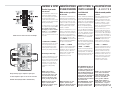 11
11
-
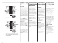 12
12
-
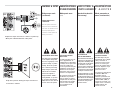 13
13
-
 14
14
-
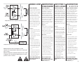 15
15
-
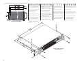 16
16
-
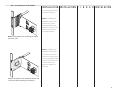 17
17
-
 18
18
-
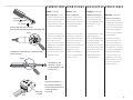 19
19
-
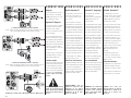 20
20
-
 21
21
-
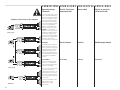 22
22
-
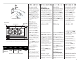 23
23
-
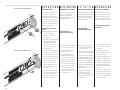 24
24
-
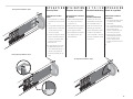 25
25
-
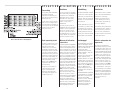 26
26
-
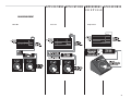 27
27
-
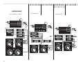 28
28
-
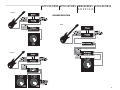 29
29
-
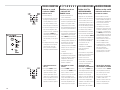 30
30
-
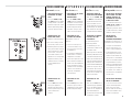 31
31
-
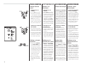 32
32
-
 33
33
-
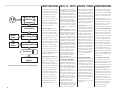 34
34
-
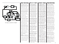 35
35
-
 36
36
-
 37
37
-
 38
38
-
 39
39
-
 40
40


QSC PL-4.0 Manuel utilisateur
- Catégorie
- Amplificateurs audio
- Taper
- Manuel utilisateur
dans d''autres langues
- English: QSC PL-4.0 User manual
- español: QSC PL-4.0 Manual de usuario
- Deutsch: QSC PL-4.0 Benutzerhandbuch
Documents connexes
-
QSC User Manual for CMX2000V Manuel utilisateur
-
QSC CMX 2000V Le manuel du propriétaire
-
QSC DCA 3422 Manuel utilisateur
-
-
QSC CX108V Manuel utilisateur
-
QSC CX1102 Manuel utilisateur
-
-
-
QSC POWERLIGHT PL340 Manuel utilisateur
-
QSC PL340 Manuel utilisateur
Autres documents
-
QSC Audio CX702 Manuel utilisateur
-
-
IMG Stage Line STA-1000 Manuel utilisateur
-
VocoPro VP-300 PRO Le manuel du propriétaire
-
Unika DSP4000 Le manuel du propriétaire
-
 Benchmark AHB2 Black Manuel utilisateur
-
IMG STAGELINE STA-2400 Le manuel du propriétaire
-
Stageline STA-250 Manuel utilisateur
-
Monacor WANTED-4/320 Manuel utilisateur
-
JVC CS-AW8040 - Arsenal 10" 4ohm 3000W DVC Subwoofer Manuel utilisateur
