Frigidaire 137111800B Manuel utilisateur
- Catégorie
- Laveuses sécheuses
- Taper
- Manuel utilisateur
Ce manuel convient également à

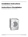
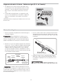
Installation Instructions
Gas & Electric Dryer
Instructions d’Installation
Sécheuse à Gaz ou Électrique
www.frigidaire.com P/N 137111800B (0903)

2
Important Safety Instructions ................................................2
Pre-installation Requirements ................................................2
Installation Requirements .................................................. 3-7
Installed Dimensions .............................................................8
Installation Instructions ................................................... 9-13
Reversing door .............................................................. 14-15
Accessories/Replacement parts ............................................16
Français ..............................................................................17
Table of Contents
Important Safety Instructions
- RISK OF FIRE - Read all of the following instructions before installing and using this appliance:
Destroy the carton and plastic bags after the dryer is unpacked. Children might use them for play. Cartons covered with •
rugs, bedspreads, or plastic sheets can become airtight chambers causing suffocation. Place all materials in a garbage
container or make materials inaccessible to children.
Clothes dryer installation and service must be performed by a qualifi ed installer, service agency or the gas supplier.•
Install the clothes dryer according to the manufacturer’s instructions and local codes.•
The electrical service to the dryer must conform with local codes and ordinances and the latest edition of the National •
Electrical Code, ANSI/NFPA 70, or in Canada, the Canadian electrical code C22.1 part 1.
The gas service to the dryer must conform with local codes and ordinances and the latest edition of the National Fuel Gas •
Code ANSI Z223.1, or in Canada, CAN/ACG B149.1-2000.
The dryer is designed under ANSI Z 21.5.1 or ANSI/UL 2158 - CAN/CSA C22.2 No. 112 (latest editions) for HOME USE •
only. This dryer is not recommended for commercial applications such as restaurants, beauty salons, etc.
Do not install a clothes dryer with fl exible plastic venting material. Flexible venting materials are known to collapse, be eas-•
ily crushed and trap lint. These conditions will obstruct clothes dryer airfl ow and increase the risk of fi re.
The instructions in this manual and all other literature included with this dryer are not meant to cover every possible •
condition and situation that may occur. Good safe practice and caution MUST be applied when installing, operating and
maintaining any appliance.
WHAT TO DO IF YOU SMELL GAS:
Do not try to light any appliance.•
Do not touch any electrical switch; do not use any phone in your building.•
Clear the room, building or area of all occupants.•
Immediately call your gas supplier from a neighbor’s phone. Follow the gas supplier’s instructions.•
If you cannot reach your gas supplier, call the fi re department.•
Save these instructions for future reference.
Pre-Installation Requirements
For your safety the information in this manual must be followed to minimize the risk of fi re or explosion or to
prevent property damage, personal injury or loss of life. Do not store or use gasoline or other fl ammable vapors and liquids in
the vicinity of this or any other appliance.
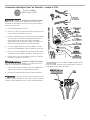
Tools and materials needed for installation:
Adjustable pliers•
Phillips, straight, & square bit screw-•
drivers
Adjustable wrench•
Pipe wrench for gas supply (gas dryer)•
LP-resistant thread tape (for natural •
gas or LP supply, gas dryer)
Carpenter’s level•
External vent hood•
4-inch (10.2 cm), rigid metal or semi-•
rigid metal exhaust duct work
3-wire or 4-wire 240 volt cord kit •
(electric dryer)
4 in. (10.2 cm) clamp•
Gas line shutoff valve (gas dryer)•
½ NPT union fl are adapters (x2) and •
fl exible gas supply line (gas dryer)
Metal foil tape (not duct tape)•
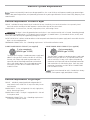
Recognize safety symbols, words and labels
Safety items throughout this manual are labeled with a
WARNING or CAUTION based on the risk type as described:
This symbol alerts you to situations that
may cause serious body harm, death or property damage.
This symbol alerts you to situations that may
cause bodily injury or property damage.

This dryer is internally grounded to neutral unless it was manufactured for sale in Canada. Grounding through
the neutral link is prohibited for: (1) new branch circuit installations, (2) mobile homes, (3) recreational vehicles, and (4) areas
where local codes do not permit grounding through the neutral.
3
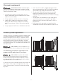
Electrical System Requirements
Electrical requirements for electric dryer
CIRCUIT - Individual 30 amp. branch circuit fused with 30 amp. time delay fuses or circuit breakers. Use separately fused
circuits for washer and dryer. DO NOT operate a washer and a dryer on the same circuit.
POWER SUPPLY - 3-wire or 4-wire, 240 volt, single phase, 60 Hz, Alternating Current.
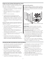
3-WIRE POWER SUPPLY CORD KIT (not supplied)
OUTLET RECEPTACLE - NEMA 10-30R or NEMA 14-30R receptacle to be located so the power supply cord is accessible when the
dryer is in the installed position.
GROUNDING CONNECTION - See “Grounding requirements” in Electrical Installation section.
The dryer MUST employ a 3-conductor power supply cord
NEMA 10-30 type SRDT rated at 240 volt AC minimum,
30 amp, with 3 open end spade lug connectors with
upturned ends or closed loop connectors and marked
for use with clothes dryers. For 3-wire cord connection
instructions see ELECTRICAL CONNECTIONS FOR A
3-WIRE SYSTEM.
4-WIRE POWER SUPPLY CORD KIT (not supplied)
The dryer MUST employ a 4-conductor power supply cord
NEMA 14-30 type SRDT or ST (as required) rated at 240
volt AC minimum, 30 amp, with 4 open end spade lug
connectors with upturned ends or closed loop connectors
and marked for use with clothes dryers. For 4-wire cord
connection instructions see ELECTRICAL CONNECTIONS
FOR A 4-WIRE SYSTEM.
Electrical requirements for gas dryer
CIRCUIT - Individual, properly polarized and grounded 15
amp. branch circuit fused with 15 amp. time delay fuse or
circuit breaker.
POWER SUPPLY - 2-wire, with ground, 120 volt, single phase,
60 Hz, Alternating Current.
POWER SUPPLY CORD - The dryer is equipped with a 120 volt
3-wire power cord.
GROUNDING CONNECTION - See “Grounding requirements”
in Electrical Installation section.
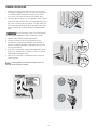
Grounding type
Grounding type
wa
wa
ll receptacl
ll receptacle
Po
Po
wer cord with
wer cord with
3-prong
3-prong
gr
gr
ounded plug
ounded plug
Do not,
Do not,
under
under
an
an
y cir
y cir
cumstances,
cumstances,
cut,
cut,
remo
remo
ve
ve,
or b
or b
ypass th
ypass the
gr
gr
ounding pr
ounding pr
ong.
ong.
3-wire receptacle
(NEMA type 10-30R)
4-wire receptacle
(NEMA type 14-30R)
Because of potentially inconsistent voltage capabilities, the use of this dryer with power created by gas powered gen-
erators, solar powered generators, wind powered generators or any other generator other than the local utility company is not
recommended.
Dryers manufactured for sale in Canada have factory-
installed, 4-wire power supply cord (NEMA 14-30R).

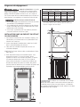
Exhaust system requirements
If your present system is made up of plastic duct or metal foil
duct, replace it with a rigid or semi-rigid metal duct. Also,
ensure the present duct is free of any lint prior to installing
dryer duct.
Use only 4 inch (10.2 cm) diameter (minimum) rigid or fl exible
metal duct and approved vent hood which has a swing-out
damper(s) that open when the dryer is in operation. When
the dryer stops, the dampers automatically close to prevent
drafts and the entrance of insects and rodents. To avoid
restricting the outlet, maintain a minimum of 12 inches (30.5
cm) clearance between the vent hood and the ground or any
other obstruction.
Correct Incorrect
Correct Incorrect
The following are specifi c requirements for
proper and safe operation of your dryer.
Gas supply requirements
1. Installation MUST conform with local codes, or in the
absence of local codes, with the National Fuel Gas Code,
ANSI Z223.1 (latest edition).
2. The gas supply line should be 1/2 inch (1.27 cm) pipe.
3. If codes allow, fl exible metal tubing may be used to
connect your dryer to the gas supply line. The tubing
MUST be constructed of stainless steel or plastic-coated
brass.
4. The gas supply line MUST have an individual shutoff valve.
5. A 1/8 inch (0.32 cm) N.P.T. plugged tapping, accessible
for test gauge connection, MUST be installed immediately
upstream of the gas supply connection to the dryer.
6. The dryer MUST be disconnected from the gas supply
piping system during any pressure testing of the gas
supply piping system at test pressures in excess of 1/2 psig
(3.45 kPa).
7. The dryer MUST be isolated from the gas supply piping
system during any pressure testing of the gas supply
piping system at test pressures equal to or less than 1/2
psig (3.45 kPa).
8. Connections for the gas supply must comply with the
Standard for Connectors for Gas Appliances, ANSI Z21.24.
4
- EXPLOSION HAZARD - Uncoated copper
tubing will corrode when subjected to natural gas, causing
gas leaks. Use ONLY black iron, stainless steel, or plastic-coat-
ed brass piping for gas supply.
- FIRE HAZARD - Failure to follow these in-
structions can create excessive drying times and fi re hazards.
- FIRE HAZARD - Do not install a clothes
dryer with fl exible plastic or metal foil venting materials.
Flexible venting materials are known to collapse, be easily
crushed and trap lint. These conditions will obstruct clothes
dryer airfl ow and increase the risk of fi re.

5
- FIRE HAZARD -
Do not allow combustible materials (for example: clothing, •
draperies/curtains, paper) to come in contact with exhaust
system. The dryer MUST NOT be exhausted into a chim-
ney, a wall, a ceiling, or any concealed space of a building
which can accumulate lint, resulting in a fi re hazard.
Do not screen the exhaust ends of the vent system, or use •
any screws, rivets or other fasteners that extend into the
duct to assemble the exhaust system. Lint can become
caught in the screen, on the screws or rivets, clogging the
duct work and creating a fi re hazard as well as increasing
drying times. Use an approved vent hood to terminate the
duct outdoors, and seal all joints with duct tape. All male
duct pipe fi ttings MUST be installed downstream with the
fl ow of air.
- FIRE HAZARD - A clothes dryer must be
exhausted outdoors. Do not exhaust dryer into a chimney, a
wall, a ceiling, an attic, a crawl space or any concealed space
of a building. A clothes dryer produces combustible lint. If
the dryer is not exhausted outdoors, some fi ne lint will be
expelled into the laundry area. An accumulation of lint in any
area of the home can create a health and fi re hazard.
- FIRE HAZARD - Exceeding the length of
duct pipe or number of elbows allowed in the “MAXIMUM
LENGTH” charts can cause an accumulation of lint in the ex-
haust system. Plugging the system could create a fi re hazard,
as well as increase drying times.
The dryer must be connected to an exhaust outdoors.
Regularly inspect the outdoor exhaust opening and remove
any accumulation of lint around the outdoor exhaust opening
and in the surrounding area.
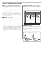
Exhaust system requirements, continued
Number of 90° turns
MAXIMUM LENGTH
of 4” (10.2cm) Rigid Metal Duct
VENT HOOD TYPE
(Preferred)
4”
(10.2cm) louvered
2.5”
(6.35cm)
0 64 ft. (19.5 m) 48 ft. (14.6 m)
1 52 ft. (15.9 m) 40 ft. (12.2 m)
2 44 ft. (13.5 m) 32 ft. (9.8 m)
3 32 ft. (9.8 m) 24 ft. (7.3 m)
4 28 ft. (9.5 m) 16 ft. (4.9 m)
Install male fi ttings in correct direction:
CORRECT
INCORRECT
- FIRE HAZARD -
Do not install fl exible plastic or fl exible foil venting mate-•
rial.
If installing semi-rigid venting, do not exceed 8 ft. (2.4 m) •
duct length.

See also CLEARANCE REQUIREMENTS on the next page.
Exhaust direction
Directional exhausting can be accomplished by installing a
quick-turn 90° dryer vent elbow directly to exhaust outlet of
dryer. Dryer vent elbows are available through your local parts
distributor or hardware store.
Exhaust system requirements, continued
In installations where the exhaust system is not described in
the charts, the following method must be used to determine
if the exhaust system is acceptable:
1. Connect an inclined or digital manometer between the
dryer and the point the exhaust connects to the dryer.
2. Set the dryer timer and temperature to air fl uff (cool
down) and start the dryer.
3. Read the measurement on the manometer.
4. The system back pressure MUST NOT be higher than
0.75 inches of water column. If the system back pressure
is less than 0.75 inches of water column, the system is
acceptable. If the manometer reading is higher than .075
inches of water column, the system is too restrictive and
the installation is unacceptable.
Although vertical orientation of the exhaust system is
acceptable, certain extenuating circumstances could affect
the performance of the dryer:
Only the rigid metal duct work should be used.•
Venting vertically through a roof may expose the exhaust •
system to down drafts causing an increase in vent
restriction.
Running the exhaust system through an uninsulated area •
may cause condensation and faster accumulation of lint.
Compression or crimping of the exhaust system will cause •
an increase in vent restriction.
The exhaust system should be inspected and cleaned a •
minimum of every 18 months with normal usage. The
more the dryer is used, the more often you should check
the exhaust system and vent hood for proper operation.
Manufactured or mobile home installation
Installation MUST conform to current Manufactured 1.
Home Construction & Safety Standard, Title 24 CFR, Part
32-80 (formerly the Federal Standard for Mobile Home
Construction and Safety, Title 24, HUD Part 280) or
Standard CAN/CSAZ240 MH.
Dryer MUST be exhausted outside (outdoors, not beneath 2.
the mobile home) using metal ducting that will not support
combustion. Metal ducting must be 4 inches (10.16 cm) in
diameter with no obstructions. Rigid metal duct is preferred.
If dryer is exhausted through the fl oor and area beneath 3.
the mobile home is enclosed, the exhaust system MUST
terminate outside the enclosure with the termination
securely fastened to the mobile home structure.
Refer to previous sections in this guide for other important 4.
exhaust venting system requirements.
When installing a gas dryer into a mobile home, a 5.
provision must be made for outside make up air. This
provision is to be not less than twice the area of the dryer
exhaust outlet.
Installer MUST anchor this (1) dryer or (2) dryer mounted 6.
on pedestal to the fl oor with approved Mobile Home
Installation Kit - P/N 137067200.
6
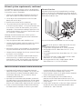
Use of 90° quick-turn elbow required to meet mini-
mum installation depth of free-standing dryer:
Straight back venting allows for 0” (0 cm) installation.•
Venting right with 90° elbow allows for 0.75” (2 cm) •
installation.
Venting downward with 90° elbow allows for 0.75” (2 cm) •
installation.
Venting left with short, straight adapter and 90° elbow •
allows for 3.75” (9.5 cm) installation.
Venting upward with short, straight adapter and 90° •
elbow allows for 4” (10.5 cm) installation.

7
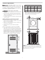
MINIMUM INSTALLATION CLEARANCES - Inches (cm)
SIDES REAR TOP FRONT
Alcove 0” (0 cm) 0” (0 cm)* 0” (0 cm) n/a
Under-
Counter
0” (0 cm) 0” (0 cm)* 0” (0 cm) n/a
Closet 0” (0 cm) 0” (0 cm)* 0” (0 cm) 1” (2.54 cm)
Clearance requirements
60 sq. in.
(387.1cm²)
3”
(7.6cm)
60 sq. in.
(387.1cm²)
3”
(7.6cm)
0”
(0cm)
0”
(0cm)
1”
(2.54cm)
0”
(0cm)
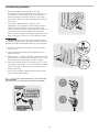
INSTALLATION IN A RECESS OR CLOSET
1. A dryer installed in a bedroom, bathroom, recess or closet,
MUST be exhausted outdoors.
2. No other fuel burning appliance shall be installed in the
same closet as the gas dryer.
3. Your dryer needs the space around it for proper
ventilation.
DO NOT install your dryer in a closet with a solid door.
4. Closet door ventilation required: A minimum of 120
square inches (774.2 cm²) of opening, equally divided at
the top and bottom of the door, is required. Openings
should be located 3 inches (7.6 cm) from bottom and top
of door. Openings are required to be unobstructed when
a door is installed. A louvered door with equivalent air
openings for the full length of the door is acceptable.
closet door
F*
or other than straight back venting, a quick-turn 90°
dryer vent elbow (vented right or down in free-standing
dryer or right on pedestal-mounted dryer) must be
installed to achieve 0” (0 cm) installation.
- EXPLOSION HAZARD - Do not install the
dryer where gasoline or other fl ammables are kept or stored.
If the dryer is installed in a garage, it must be a minimum
of 18 inches (45.7 cm) above the fl oor. Failure to do so can
result in death, explosion, fi re or burns.
DO NOT INSTALL YOUR DRYER:
In an area exposed to dripping water or outside weather 1.
conditions.
In an area where it will come in contact with curtains, 2.
drapes, or anything that will obstruct the fl ow of com-
bustion and ventilation air.
On carpet. Floor MUST be solid with a maximum slope of 3.
1 inch (2.54 cm).
To achieve an installation with 0” (0 cm) clearance
for the back of the dryer (for other than straight back vent-
ing), a quick-turn 90° dryer vent elbow must be installed as
described previously in this manual.

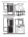
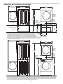
36.0”
(91.5cm)
16.9”
(43cm)
19.0”
(48cm)
51.25”
(130cm)
1.6”
(4cm)
3.75”
(9.5cm)
13.50”
(34.5cm)
to center of rear vent
3.7”
(9.5cm)
gas supply
pipe on rear
of gas unit
48.25” (122.5cm)*
to clear open door
30.5” (77.5cm)*
to front of closed door
27.0”
(68.5cm)
centerline
height for
rear vent
electrical
supply on
rear of unit
freestand dryer
on floor
floor line
floor line
dryer mounted on
optional pedestal
* To obtain these minimal depth dimensions, dryer must be vented straight back.
Using a quick-turn 90° elbow (right or down on freestanding dryer) adds approximately
0.75 in. (2.0 cm) to installation depth. Upward venting of exhaust on pedestal-mounted
or freestanding dryer adds approximately 4 in. (10.2 cm) to installation depth. Leftward
venting on pedestal-mounted or freestanding dryer adds approximately 3.75 in. (9.5 cm)
to installation depth. Downward venting of exhaust on pedestal-mounted dryer adds
approximately 2.25 in. (5.7 cm) to installation depth.
* To obtain these minimal depth dimensions, dryer must be vented straight back. Using a quick-turn 90° elbow (right) adds approximately 0.75 in. (2 cm) to
installation depth. Upward venting of exhaust on stacked dryer adds approximately 4 in. (10.2 cm) to installation depth. Downward venting of exhaust on
stacked dryer adds approximately 2.25 in. (6.5 cm) to installation depth. Leftward venting of exhaust on stacked dryer adds approximately 3.75 in. (9.5 cm) to
installation depth.
71.5”
(182cm)
39”
(99cm)
37”
(94cm)
gas supply
pipe on rear
of gas unit
48.25” (122.5cm)*
to clear open door
30.5” (77.5cm)*
to front of closed door
centerline
height for
rear vent
electrical
supply on
rear of unit
27.0”
(68.5cm)
Installed dryer dimensions
8

9
The following are specifi c requirements for proper and safe
electrical installation of your dryer. Failure to follow these
instructions can create electrical shock and/or a fi re hazard.
Grounding requirements - Electric dryer (USA)
Electrical installation
For a grounded, cord-connected dryer:
1. The dryer MUST be grounded. In the event of a
malfunction or breakdown, grounding will reduce the
risk of electrical shock by a path of least resistance for
electrical current.
2. After you purchase and install a 3 wire or 4 wire power
supply cord having an equipment-grounding conductor
and a grounding plug that matches you wiring system,
- ELECTRICAL SHOCK HAZARD -
This appliance MUST be properly grounded. Electrical •
shock can result if the dryer is not properly grounded.
Follow the instructions in this manual for proper ground-
ing.
Do not use an extension cord with this dryer. Some ex-•
tension cords are not designed to withstand the amounts
of electrical current this dryer utilizes and can melt, creat-
ing electrical shock and/or fi re hazard. Locate the dryer
within reach of the receptacle for the length power cord
to be purchased, allowing some slack in the cord. Refer
to the pre-installation requirements in this manual for the
proper power cord to be purchased.
- ELECTRICAL SHOCK HAZARD -
A U.L.-approved strain relief must be installed onto pow-•
er cord. If the strain relief is not attached, the cord can be
pulled out of the dryer and can be cut by any movement
of the cord, resulting in electrical shock.
Do not use an aluminum wired receptacle with a copper •
wired power cord and plug (or vice versa). A chemical
reaction occurs between copper and aluminum and can
cause electrical shorts. The proper wiring and receptacle
is a copper wired power cord with a copper wired recep-
tacle.
Dryers operating on 208 volt power supply will have
longer drying times than dryers operating on 240 volt power
supply.
- ELECTRICAL SHOCK HAZARD - Improper
connection of the equipment grounding conductor can result
in a risk of electrical shock. Check with a licensed electrician
if you are in doubt as to whether the appliance is properly
grounded.
the plug MUST be plugged into an appropriate, copper
wired receptacle that is properly installed and grounded
in accordance with all local codes and ordinances. If in
doubt, call a licensed electrician.
DO NOT modify the plug you’ve installed on this appliance.
For a permanently connected dryer:
1. The dryer MUST be connected to a grounded metal,
permanent wiring system; or an equipment grounding
conductor must be run with the circuit conductors and
connected to the equipment-grounding terminal or lead
on the appliance.
Grounding requirements - Electric dryer (Canada)
For a grounded, cord-connected dryer:
1. The dryer MUST be grounded. In the event of a
malfunction or breakdown, grounding will reduce the
risk of electrical shock by a path of least resistance for
electrical current.
- ELECTRICAL SHOCK HAZARD - Improper
connection of the equipment grounding conductor can result
in a risk of electrical shock. Check with a licensed electrician
if you are in doubt as to whether the appliance is properly
grounded.
2. Since your dryer is equipped with a power supply
cord having an equipment-grounding conductor and
a grounding plug, the plug must be plugged into an
appropriate outlet that is properly installed and grounded
in accordance with all local codes and ordinances. If in
doubt, call a licensed electrician.
DO NOT modify the plug provided with the appliance.

The dryer is equipped with a three-prong (grounding) plug 1.
for your protection against shock hazard and should be
plugged directly into a properly grounded three-prong
receptacle.
The plug must be plugged into an appropriate outlet that 2.
is properly installed and grounded in accordance with all
local codes and ordinances. If in doubt, call a licensed
electrician.
DO NOT cut or remove ground prong from the plug.
Grounding type
Grounding type
wa
wa
ll receptacl
ll receptacle
Po
Po
wer cord with
wer cord with
3-prong
3-prong
gr
gr
ounded plug
ounded plug
Do not,
Do not,
under
under
an
an
y cir
y cir
cumstances,
cumstances,
cut,
cut,
remo
remo
ve
ve,
or b
or b
ypass th
ypass the
gr
gr
ounding pr
ounding pr
ong.
ong.
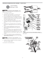
Grounding requirements - Gas dryer (USA and Canada)
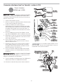
Gas connection
Remove the shipping cap from gas pipe at the rear of the 1.
dryer.
Connect a 1/2 inch (1.27 cm) I.D. semi-rigid or approved 2.
pipe from gas supply line to the 3/8 inch (0.96 cm) pipe
located on the back of the dryer. Use a 1/2 inch to 3/8
inch (1.27 cm to 0.96 cm) reducer for the connection.
Apply an approved thread sealer that is resistant to the
corrosive action of liquefi ed gases on all pipe connections.
Open the shutoff valve in the gas supply line to allow gas 3.
to fl ow through the pipe. Wait a few minutes for gas to
move through the gas line.
All connections must be wrench-tightened
Flare
Union
Flare
Union
GAS FLOW
Manual
Shuto
Valve
Closed
Open
Flexible
Connector
Inlet Pipe on
Back of Dryer
elppiN
Shuto Valve -
Open position
to dryer
from gas supply
Check for gas system leaks with a manometer. If a 4.
manometer is not available, test all connections by
brushing on a soapy water solution.
10
- EXPLOSION HAZARD - NEVER test for gas
leaks with an open fl ame.
The supply line must be equipped with an ap-
proved manual shutoff valve. This valve should be located in
the same room as the dryer and should be in a location that
allows ease of opening and closing. Do not block access to
the gas shutoff valve.
DO NOT connect the dryer to L.P. gas service
without converting the gas valve. An L.P. conversion kit must
be installed by a qualifi ed gas technician.

11
Electrical connection (non-Canada) - 3 wire cord
Turn off power supply to outlet. 1.
Remove the screw securing the terminal block access 2.
cover in the lower corner on the back of the dryer.
Install a UL-approved strain relief according to the power 3.
cord/strain relief manufacturer’s instructions in the power
cord entry hole below the access panel. At this time, the
strain relief should be loosely in place.
Thread an UNPLUGGED, UL-approved, 30 amp. power 4.
cord, NEMA 10-30 type SRDT, through the strain relief.
Attach the power cord neutral (center wire) conductor to 5.
the SILVER colored center terminal on the terminal block.
Tighten the screw securely.
Attach the remaining two power cord outer conductors 6.
to the outer, BRASS colored terminals on the terminal
block. Tighten both screws securely.
3-wire receptacle
(NEMA type 10-30R)
Internal ground
Internal ground
(GREEN screw)
(GREEN screw)
Install
Install
UL-approved
UL-approved
strain relief here
strain relief here
Terminal screw
Terminal screw
recovery slot
recovery slot
Line 1
Line 1
(BRASS terminal)
(BRASS terminal)
Neutral
Neutral
(SILVER terminal)
(SILVER terminal)
Line 2
Line 2
(BRASS terminal)
(BRASS terminal)
Access cover
Access cover
screw
screw
Terminal
Terminal
block
block
Neutral
Neutral
(center wire)
(center wire)
30 AMP
30 AMP
NEMA 10-30
NEMA 10-30
Follow manufacturer’s guidelines for fi rmly securing the 7.
strain relief and power cord.
Reinstall the terminal block cover.8.
DO NOT remove
DO NOT remove
internal ground in
internal ground in
a 3-wire system!!
a 3-wire system!!
Neutral
Neutral
terminal
terminal
- ELECTRICAL SHOCK HAZARD - Failure
to disconnect power source before servicing could result in
personal injury or even death.
- ELECTRICAL SHOCK HAZARD - Do not
make a sharp bend or crimp wiring/conductor at connections.
If moving dryer from a 4-wire system and
installing it in a 3-wire system, move the internal ground from
the center terminal back to the GREEN screw next to the
terminal block.
If a terminal screw falls during cord installation, it
can be retrieved in the terminal screw recovery slot below the
access panel.

4-wire receptacle
(NEMA type 14-30R)
Electrical connection (non-Canada) - 4 wire cord
Turn off power supply to outlet. 1.
Remove the screw securing the terminal block access 2.
cover in the lower corner on the back of the dryer.
Install a UL-approved strain relief according to the power 3.
cord/strain relief manufacturer’s instructions in the power
cord entry hole below the access panel. At this time, the
strain relief should be loosely in place.
Thread an UNPLUGGED, UL-approved, 30 amp. power 4.
cord, NEMA 14-30 type ST or SRDT, through the strain
relief.
Disconnect the internal (BLACK) dryer harness ground 5.
wire from the (GREEN) ground screw next to the terminal
block.
Attach the ground (GREEN) power cord wire to the 6.
cabinet with the ground (GREEN) screw. Tighten the
screw securely.
Move the internal dryer harness ground (BLACK) wire to 7.
the terminal block and attach it along with the neutral
(WHITE) power cord wire conductor to the center, SILVER
colored terminal on the terminal block. Tighten the screw
securely.
Attach the RED and BLACK power cord conductors to 8.
the outer, BRASS colored terminals on the terminal block.
Tighten both screws securely.
Internal ground
Internal ground
(GREEN screw)
(GREEN screw)
Install
Install
UL-approved
UL-approved
strain relief here
strain relief here
Terminal screw
Terminal screw
recovery slot
recovery slot
Line 1
Line 1
(BRASS terminal)
(BRASS terminal)
Neutral
Neutral
(SILVER terminal)
(SILVER terminal)
Line 2
Line 2
(BRASS terminal)
(BRASS terminal)
Access cover
Access cover
screw
screw
Terminal
Terminal
block
block
Neutral
Neutral
(WHITE wire)
(WHITE wire)
30 AMP
30 AMP
NEMA 14-30
NEMA 14-30
Ground
Ground
(GREEN wire)
(GREEN wire)
Follow manufacturer’s guidelines for fi rmly securing the 9.
strain relief and power cord.
Reinstall the terminal block cover.10.
Move internal ground (BLACK)
Move internal ground (BLACK)
wire to neutral (SILVER)
wire to neutral (SILVER)
terminal for 4-wire system.
terminal for 4-wire system.
Neutral
Neutral
terminal
terminal
GREEN
GREEN
ground screw
ground screw
BLACK or
BLACK or
RED power wire
RED power wire
BLACK
BLACK
or RED
or RED
power wire
power wire
GREEN
GREEN
ground wire
ground wire
WHITE
WHITE
neutral wire
neutral wire
12
- ELECTRICAL SHOCK HAZARD - Failure
to disconnect power source before servicing could result in
personal injury or even death.
- ELECTRICAL SHOCK HAZARD - Do not
make a sharp bend or crimp wiring/conductor at connections.
If a terminal screw falls during cord installation, it
can be retrieved in the terminal screw recovery slot below the
access panel.

13
General installation
Grounding type
Grounding type
wa
wa
ll receptacl
ll receptacle
Po
Po
wer cord with
wer cord with
3-prong
3-prong
gr
gr
ounded plug
ounded plug
Do not,
Do not,
under
under
an
an
y cir
y cir
cumstances,
cumstances,
cut,
cut,
remo
remo
ve
ve,
or b
or b
ypass th
ypass the
gr
gr
ounding pr
ounding pr
ong.
ong.
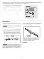
Connect the exhaust duct to the outside exhaust system 1.
(see pages 4 through 6). Use of a 4” (10.2 cm) clamp (item
A) is recommended to connect the dryer to the exhaust
vent system. Use metal foil tape to seal all other joints.
Carefully slide the dryer to its fi nal position. Adjust one or 2.
more of the legs until the dryer is resting solidly on all four
legs. Place a level on top of the dryer. The dryer MUST be
level and resting solidly on all four legs. Rock alternating
corners to check for stability. Remove and discard door
tape.
Plug the power cord into a grounded outlet.3.
Turn on the power at the circuit breaker/fuse box.4.
Read the5. Use & Care Guide provided with the dryer. It
contains valuable and helpful information that will save
you time and money.
If you have any questions during initial operation, please 6.
review the “Avoid Service Checklist” in your Use & Care
Guide before calling for service.
Place these instructions in a location near the dryer for 7.
future reference.
Be sure the power is off at a circuit breaker/
fuse box before plugging the power cord into an outlet.
A wiring diagram and technical data sheet are
located inside the dryer console.
A

14
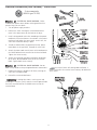
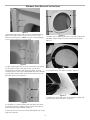
Figure 1
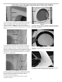
1.Open door and remove four (4) plugs in the door opening
opposite the hinges. Retain all parts for uses later, unless
otherwise noted. (Figure 1) Note: Use care in removing plugs
in not scratching paint on the front panel.
Figure 2
2. Begin removing the four (4) screws that attach the hinge to
the front panel. (Figure 2) For best results, start by only
removing one screw per hinge. Then only loosen the two
remaining screws while firmly holding door to prevent damage
to hinge, front panel or door. After the remaining screws are
loosened, continue to remove all.
Figure 3
3. Place door on a towel or pad handle side down to prevent
any possible scratches to door. Remove all remaining four (4)
screws between hinge and door. (Figure 3)
4. Remove four (4) screws from side of door opposite of where
hinge was mounted.
Figure 4
5. Remove two (2) door handle screws and two (2) hole plugs
from door. Again taking care not to scratch paint on door.
(Figure 4)
Figure 5
6. Pull handle away from door assembley. (Figure 5)
Figure 6
7. Separate the outer door from the inner door assembly with
a putty knife or flat screw driver. (Figure 6)
Window Door Reversal Instructions

15
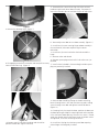
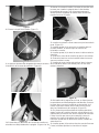
Figure 7
8. Remove lens locating screw. (Figure 7)
Figure 8
9. Disengaging several of the retention tabs and pull lens away
from the transition ring. (Figure 8)
Figure 9
Figure 10
10. Remove two (2) transition ring plugs and reinstall on
previous handle side. (Figures 9 and 10)
11. Reassemble lens to transition ring with holes to install
handle on right-hand side of door assembly. For proper fit
insure the retention tabs on transition ring are on top of lens
Figure 11
12. Reassembly outer door to inner door assembly. (Figure 11)
13. Install four (4) screws securing hinge to door assembly in
the new location, take note to place hinge in correct
orientation.
14. Install four (4) screws into holes that had secured the
hinge.
15. Remove striker and discard.
16. Remove square plug and reinstall in hole striker was just
removed.
17. Install striker (included in literature bag) into hole square
plug was previously installed.
Figure 12
18. Reinstall door handle by placing the handle mounting
bosses through holes in lens and transition ring and installing
screws through inner door and tighten into handle bosses.
(Figure 12).
19. Grasping firmly the top of the door, position the door near
the door opening and align the top hinge hole to the top hole
in the front panel door opening. Once the first screw is started,
attach the second screw to the lower hinge. Once both screws
are tightened, install the remaining two screws.
20. Install four (4) plugs into the front panel door opening
where hinges were originally installed.

26.44”
26.44”
(67.16cm)
(67.16cm)
15.00”
15.00”
(38.10cm)
(38.10cm)
27.00”
27.00”
(68.58cm)
(68.58cm)
16
Replacement parts: 1-800-944-9044 (in Canada 1-800-265-8352)
If replacements parts are needed for your dryer, contact
the source where you purchased your dryer, call 1-800-
944-9044 (au Canada 1-800-265-8352), or visit our
website, www.frigidaire.com, for the Frigidaire Authorized
Parts Distributor nearest you.
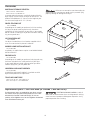
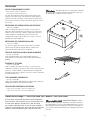
Accessories
MATCHING STORAGE PEDESTAL
White Pedestal - P/N NLPWD15
Black Pedestal - P/N NLPWD15E
A storage pedestal accessory, specifi cally designed for this
dryer may be used to elevate the dryer for ease of use. This
pedestal will add about 15” (38 cm) to the height of your
unit for a total height of 51.25” (130 cm).
DRYER STACKING KIT
P/N 134700600
Depending on the model you purchased, a kit for stacking
this dryer on top of matching washer may have been
included in the initial purchase of your dryer. If your model
did not include a stacking kit or you desire another stacking
kit, you may order one.
LP CONVERSION KIT
P/N PCK4200
Gas dryers intended for use in a location supplied with LP
must use a conversion kit prior to installation.
MOBILE HOME INSTALLATION KIT
P/N 137067200
Installations in mobile homes require use of MOBILE HOME
INSTALLATION KIT.
DRYING RACK
P/N 137067300
Depending on the model you purchased, a drying rack may
have been included in the initial purchase of your dryer.
If your model did not include a drying rack or you desire
another drying rack, you may order one.
UNIVERSAL APPLIANCE WRENCH
P/N 137019200
A UNIVERSAL APPLIANCE WRENCH is available to aid in
dryer/washer/pedestal feet adjustment.
TOUCH UP PAINT PENS
White Touch Up Pen - P/N 5303321319
Black Touch Up Pen - P/N 5304458932
Failure to use accessories manufactured by (or
approved by) the manufacturer could result in personal injury,
property damage or damage to the dryer.
- ELECTRICAL SHOCK HAZARD - Label all
wires prior to disconnection when servicing controls. Wiring
errors can cause improper and dangerous operation. Verify
proper operation after servicing.

17
Mesures de sécurité importantes
- RISQUE D’INCENDIE - Lisez toutes les instructions de sécurité suivantes avant d’installer et d’utili-
ser votre appareil :
Détruisez le carton d’emballage et les sacs en plastique après avoir déballé l’appareil. Les enfants pourraient les utiliser pour jouer. •
Le carton recouvert de tapis, les couvertures et les feuilles de plastique peuvent être étanches à l’air et provoquer la suffocation.
Déposez tous les matériaux d’emballage dans un conteneur à déchets ou faites en sorte que les enfants ne puissent y avoir accès.
L’installation et l’entretien de cette sécheuse doivent être réalisés par un installateur qualifi é, un technicien de service ou le •
fournisseur de gaz.
Installez l’appareil conformément aux instructions du fabricant et aux codes locaux.•
L’installation électrique de la sécheuse doit être conforme aux codes et aux règlements locaux ainsi qu’à la toute dernière •
édition du National Electrical Code (ANSI/NFPA 70), ou au Canada, au Code canadien de l’électricité (C22.1, article 1).
L’installation de gaz de la sécheuse doit être conforme aux codes et aux règlements locaux ainsi qu’à la toute dernière •
édition du Fuel Gas Code (ANSI Z223.1), ou au Canada, au CAN/ACG B149.1-2000.
La sécheuse est classée, en vertu des règlements ANSI Z 21.5.1 ou ANSI/UL 2158 - CAN/CSA C22.2 Nº 112 (dernières •
versions), pour un USAGE DOMESTIQUE uniquement. Il n’est pas recommandé d’utiliser cette sécheuse pour des usages
commerciaux, comme des restaurants, des salons de coiffure, etc.
N’installez pas une sécheuse avec du matériel d’évacuation en plastique ou en feuille métallique fl exible. Le matériel de •
ventilation fl exible peut s’écraser facilement et emprisonner la charpie. Ces conditions nuiraient à l’écoulement d’air de
votre sécheuse et pourraient accroître le risque d’incendie.
Les instructions comprises dans ce guide et toute autre documentation fournie avec cet appareil ne sont pas conçues pour •
couvrir toutes les éventualités ou situations qui pourraient survenir. Vous DEVEZ faire preuve de bon sens et de prudence
durant l’installation, l’utilisation et l’entretien de tout appareil ménager.
QUE FAIRE SI VOUS DÉTECTEZ UNE ODEUR DE GAZ :
Ne mettez pas d’appareil en marche.•
Ne touchez à aucun commutateur électrique; n’utilisez aucun téléphone de votre domicile.•
Évacuez la pièce, le bâtiment ou la zone touchée.•
En utilisant le téléphone d’un voisin, appelez immédiatement le fournisseur de gaz. Suivez ses instructions.•
Si vous ne pouvez joindre votre fournisseur de gaz, appelez les pompiers.•
Conservez ces instructions pour vous y reporter ultérieurement.
Exigences avant l’installation
Pour votre sécurité, l’information contenue dans ces instructions doit être suivie afi n de réduire les ris-
ques d’incendie ou d’explosion ou pour prévenir les dommages matériels, les blessures ou la mort. Vous ne devez ni entreposer, ni
utiliser d’essence ou d’autres vapeurs ou liquides infl ammables à proximité de cet appareil ou de tout autre appareil électroménager.
Outils et matériel nécessaires à l’installation :
Pince réglable•
Tournevis Phillips à pointe plate et à •
pointe carrée
Clé à molette•
Clé à tuyau pour l’alimentation en gaz•
Ruban à fi letage résistant au GPL •
(pour l’alimentation en gaz naturel ou
en GPL)
Niveau de charpentier•
Évent extérieur•
Conduit d’évacuation de 10,2 cm (4 •
po) en métal rigide ou semi-rigide
Ensemble pour cordon d’alimenta-•
tion de 240 V à 3 ou 4 fi ls (sécheuse
électrique)
Collier de 10,2 cm (4 po)•
Robinet d’arrêt pour conduite de gaz •
(sécheuse à gaz)
Deux raccords-unions à évasement de •
1/2 po (1,3 cm) NPT et une conduite
fl exible d’alimentation en gaz (sé-
cheuse à gaz)
Ruban métallique (et non du ruban à •
conduits)
Table des matières
Mesures de sécurité importantes .........................................17
Exigences avant l’installation ...............................................17
Exigences d’installation ................................................. 18-22
Dimensions, appareil installé ...............................................23
Instructions d’installation .............................................. 24-28
Inversion de la porte ..................................................... 29-30
Accessoires/Pièces de rechange ...........................................31
Sachez reconnaître les symboles, les avertisse-
ments et les étiquettes de sécurité.
Les mesures de sécurité présentées dans ce guide sont identi-
fi ées par le mot AVERTISSEMENT ou ATTENTION selon le type
de risque présenté.
Ce symbole vous avertit à propos
des situations pouvant causer des dommages matériels, des
blessures graves ou même la mort.
Ce symbole vous avertit à propos des
situations pouvant causer des dommages matériels ou des
blessures.

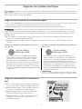
Prise murale avec
Prise murale avec
mise à la terre
mise à la terre
à la terre de cette che.
à la terre de cette che.
Ne coupez pas, n'enlevez
Ne coupez pas, n'enlevez
pas et ne mettez pas hors
pas et ne mettez pas hors
circuit la broche de mise
circuit la broche de mise
Cordon électrique muni
Cordon électrique muni
avec mise à la terre
avec mise à la terre
d’une che à trois broches
d’une che à trois broches
Cette sécheuse est mise à la terre par le fi l d’alimentation neutre, sauf si elle est destinée à la vente au Ca-
nada. La mise à la terre par le fi l d’alimentation neutre est interdit pour : (1) un nouveau circuit de dérivation, (2) les maisons
mobiles, (3) les véhicules récréatifs, et (4) les régions où les codes locaux ne permettent pas la mise à la terre par le fi l d’ali-
mentation neutre.
Exigences des systèmes électriques
Exigences électriques de la sécheuse électrique:
CIRCUIT - Circuit indépendant de 30 ampères avec fusible temporisé ou disjoncteur de 30 A. Utilisez des circuits indépendants
pour la laveuse et la sécheuse. NE BRANCHEZ PAS la laveuse et la sécheuse sur le même circuit.
ALIMENTATION ÉLECTRIQUE - Câble monophasé à trois ou quatre fi ls, 240 volts, 60 Hz; courant alternatif.
TROUSSE DE CORDON D’ALIMENTATION À TROIS FILS
(non fournie)
PRISE - Prise NEMA 10-30R ou NEMA 14-30R située de manière à permettre l’accès au cordon d’alimentation lorsque la
sécheuse est à sa position de fonctionnement.
CONNEXION DE MISE À LA TERRE - Consultez la rubrique « Exigences de mise à la terre » dans la section d’installation
électrique.
La sécheuse DOIT utiliser un cordon d’alimentation à
trois fi ls NEMA 10-30 de type SRDT d’une capacité de
240 volts (c.a.) et d’au moins 30 ampères, avec trois
connecteurs ouverts embrochables avec extrémités
renversées, ou connecteurs à boucle fermée, spécialement
indiqués pour une utilisation avec une sécheuse. Pour les
instructions de raccordement du cordon à 3 fi ls, consultez
la section CONNEXIONS ÉLECTRIQUES POUR UN SYSTÈME
À TROIS FILS.
TROUSSE DE CORDON D’ALIMENTATION À QUATRE FILS
(non fournie)
La sécheuse DOIT utiliser un cordon d’alimentation à
quatre fi ls NEMA 14-30 de type SRDT d’une capacité de
240 volts (c.a.) et d’au moins 30 ampères, avec quatre
connecteurs ouverts embrochables avec extrémités
renversées, ou connecteurs à boucle fermée, spécialement
indiqués pour une utilisation avec une sécheuse. Pour
les instructions de raccordement du cordon à quatre fi ls,
consultez la section CONNEXIONS ÉLECTRIQUES POUR UN
SYSTÈME À QUATRE FILS.
Exigences électriques de la sécheuse à
gaz:
CIRCUIT - Circuit indépendant de 15 ampères, polarisé et mis
à la terre, avec fusible temporisé ou disjoncteur de 15 A.
ALIMENTATION ÉLECTRIQUE - Câble monophasé à deux fi ls
mis à la terre, 120 volts, 60 Hz; courant alternatif.
CORDON D’ALIMENTATION - La sécheuse est dotée d’un
cordon d’alimentation de 120 volts à trois fi ls.
CONNEXION DE MISE À LA TERRE - Consultez la rubrique
« Exigences de mise à la terre » dans la section
d’installation électrique.
Prise à 3 alvéoles
(NEMA type 10-30R)
Prise à 4 alvéoles
(NEMA type 14-30R)
Étant donné les variations de tension possibles, l’utilisation de cette sécheuse avec une source d’alimentation
produite par une génératrice à essence, solaire ou éolienne ou par toute autre source d’alimentation différente de celle fournie
par les services publics n’est pas recommandée.
Les sécheuses destinées à la vente au Canada
sont munies d’un cordon d’alimentation à 4 fi ls (NEMA 14-30R).
18

19
19
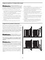
Exigences du système d’évacuation
Si votre système actuel utilise une conduite en plastique ou en
feuille métallique, remplacez-la par une conduite métallique
rigide ou semi-rigide. De plus, assurez-vous que la conduite
en place est libre de charpie avant d’installer la conduite de
sécheuse.
Utilisez seulement des conduites métalliques rigides ou fl exibles
d’au moins 10,2 cm (4 po) de diamètre, et une bouche
d’évacuation qui possède un ou des volets qui s’ouvrent lorsque
l’appareil est en fonction. Lorsque la sécheuse s’arrête, les volets
se ferment automatiquement pour empêcher les infi ltrations
d’air, d’insectes et de rongeurs. Pour éviter de bloquer la sortie,
gardez un espace minimal de 30,5 cm (12 po) entre le bas de la
bouche d’évacuation et le sol ou toute autre obstruction.
Correct Incorrect
Correct Incorrect
Vous trouverez ci-dessous les exigences pour
l’utilisation adéquate et sécuritaire de votre
appareil.
Exigences relatives à l’alimentation en gaz
1. L’installation DOIT être conforme aux codes locaux ou au
code national sur le combustible, ANSI Z223.1 (dernière
version), s’il n’existe pas de codes locaux.
2. Le tuyau d’alimentation en gaz doit être d’un diamètre
intérieur de 1,27 cm (1/2 po).
3. Si les codes le permettent, un tuyau métallique fl exible
peut être utilisé pour raccorder votre sécheuse au tuyau
d’alimentation en gaz. Le tuyau DOIT être fabriqué
en acier inoxydable ou en laiton avec revêtement en
plastique.
4. Le tuyau d’alimentation en gaz DOIT être muni d’un
robinet d’arrêt distinct.
5. Un orifi ce taraudé de 0,32 cm (1/8 po) bouché, accessible
pour le branchement de la jauge d’essai, DOIT être
installé directement en amont du branchement du tuyau
d’alimentation en gaz avec la sécheuse.
6. Cette sécheuse DOIT être débranchée de la canalisation
de gaz pendant toute vérifi cation de pression de la
canalisation de gaz à des pressions supérieures à 3,45 kPa
(1/2 lb/po2).
7. Cette sécheuse DOIT être isolée de la canalisation de gaz
pendant toute vérifi cation de pression de la canalisation
de gaz à des pressions égales ou inférieures à 3,45 kPa
(1/2 lb/po2).
8. Les branchements d’alimentation en gaz doivent être
conformes à la norme Connectors for Gas Appliances
(Raccords pour appareils au gaz) ANSI Z21.24.
- RISQUE D’EXPLOSION -
Un tuyau
en cuivre sans revêtement se corrode lorsqu’il entre en contact
avec le gaz naturel, entraînant des fuites. Utilisez SEULEMENT
des tuyaux en fer noir, en acier inoxydable ou encore en cuivre
avec revêtement en plastique pour l’alimentation en gaz.
- RISQUE D’INCENDIE - Le non-res-
pect de ces instructions pourrait augmenter démesurément
les temps de séchage et entraîner des risques d’incendie.
- RISQUE D’INCENDIE - N’installez
pas une sécheuse avec du matériel d’évacuation en plastique
ou en feuille métallique fl exible. Le matériel de ventilation
fl exible peut s’écraser facilement et emprisonner la charpie.
Ces conditions nuiraient à l’écoulement d’air de votre sécheu-
se et pourraient accroître le risque d’incendie.

20
- RISQUE D’INCENDIE -
Ne laissez pas de matière combustible (par exemple : des •
vêtements, des rideaux, du papier) entrer en contact avec
le système d’évacuation. La sécheuse NE DOIT PAS être
évacuée dans une cheminée, un mur, un plafond, ou dans
tout espace confi né d’un bâtiment qui pourrait accumuler
la charpie, entraînant un risque d’incendie.
Ne placez pas de grillage à l’extrémité du système d’éva-•
cuation, ni de vis, de rivet ou autre fi xation de manière à
ce qu’ils se prolongent dans la conduite du système d’éva-
cuation. De la charpie pourrait s’accumuler sur le grillage,
les vis ou les rivets, et obstruer l’écoulement d’air dans le
système, entraînant un risque d’incendie et l’augmenta-
tion des temps de séchage. Utilisez une bouche d’évacua-
tion approuvée pour terminer la conduite à l’extérieur, et
scellez tous les joints avec du ruban à conduits. Toutes les
extrémités mâles des conduites doivent être installées en
aval relativement au sens de l’écoulement d’air.
- RISQUE D’INCENDIE - Une sé-
cheuse doit être évacuée vers l’extérieur. N’évacuez pas une
sécheuse dans une cheminée, un mur, un plafond, un grenier,
un vide sanitaire ou dans tout espace clos d’un bâtiment. La
sécheuse produit de la charpie infl ammable. Si la sécheuse
n’est pas évacuée vers l’extérieur, de la charpie pourrait être
évacuée dans l’aire de buanderie. L’accumulation de charpie
dans toute pièce de la maison peut entraîner des risques pour
la santé et des risques d’incendie.
- RISQUE D’INCENDIE - Le fait de
dépasser la longueur de conduites ou le nombre de coudes
indiqués dans les tableaux de « LONGUEUR MAXIMALE »
peut entraîner l’accumulation de charpie dans le système.
Toute obstruction au système d’évacuation peut entraîner un
risque d’incendie, en plus d’accroître le temps de séchage.
La sécheuse doit être branchée à une évacuation extérieure.
Inspectez régulièrement l’ouverture de l’évacuation extérieure
et retirez toute accumulation de charpie près de l’ouverture et
de la région avoisinante.
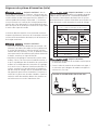
Exigences de système d’évacuation (suite)
Nombre de tours à 90°
LONGUEUR MAXIMALE
pour le conduit en métal rigide de 10,2 cm (4 po)
TYPE DE BOUCHE D’ÉVACUATION
(De préférence)
4”
(10.2cm) À volets
2.5”
(6.35cm)
0 64 ft. (19.5 m) 48 ft. (14.6 m)
1 52 ft. (15.9 m) 40 ft. (12.2 m)
2 44 ft. (13.5 m) 32 ft. (9.8 m)
3 32 ft. (9.8 m) 24 ft. (7.3 m)
4 28 ft. (9.5 m) 16 ft. (4.9 m)
Installez les raccords mâles dans le bon sens :
CORRECT
INCORRECT
- RISQUE D’INCENDIE -
N’installez pas de matériel de ventilation en plastique ou •
en aluminium fl exible.
Si vous installez du matériel de ventilation semi-rigide, il •
est nécessaire que la longueur du conduit soit égale ou
inférieure à 2,4 m (8 pi).
La page charge ...
La page charge ...
La page charge ...
La page charge ...
La page charge ...
La page charge ...
La page charge ...
La page charge ...
La page charge ...
La page charge ...
La page charge ...
La page charge ...
-
 1
1
-
 2
2
-
 3
3
-
 4
4
-
 5
5
-
 6
6
-
 7
7
-
 8
8
-
 9
9
-
 10
10
-
 11
11
-
 12
12
-
 13
13
-
 14
14
-
 15
15
-
 16
16
-
 17
17
-
 18
18
-
 19
19
-
 20
20
-
 21
21
-
 22
22
-
 23
23
-
 24
24
-
 25
25
-
 26
26
-
 27
27
-
 28
28
-
 29
29
-
 30
30
-
 31
31
-
 32
32


Frigidaire 137111800B Manuel utilisateur
- Catégorie
- Laveuses sécheuses
- Taper
- Manuel utilisateur
- Ce manuel convient également à
dans d''autres langues
- English: Frigidaire 137111800B User manual
Documents connexes
-
Frigidaire 137112300B Manuel utilisateur
-
-
-
-
-
Frigidaire FASG7073LA0 Guide d'installation
-
-
-
-
Crosley CDEC400FW1 Guide d'installation
Autres documents
-
-
-
Haier GDE450AW Manuel utilisateur
-
-
Kenmore 41781102000 Guide d'installation
-
-
Haier CHDE5000AW Manuel utilisateur
-
KitchenAid YKEHS01PMT0 Le manuel du propriétaire
-
Electrolux EIGD55H Manuel utilisateur
-
Electrolux EIGD55H Manuel utilisateur