Zanussi ZHC950ALU Manuel utilisateur
- Catégorie
- Hottes
- Taper
- Manuel utilisateur

Cappa
Cooker hood
Hotte de cuisine
Dunstabzugshaube
Dampkap
ZHC 950
MANUALE DI INSTALLAZIONE, USO E MANUTENZIONE
INSTALLATION, USE AND MAINTENANCE HANDBOOK
MANUEL D’INSTRUCTIONS POUR L’INSTALLATION, L’EMPLOI ET L’ENTRETIEN
HANDBUCH FÜR INSTALLATION, BEDIENUNG UND WARTUNG
INSTRUCTIES VOOR MONTAGE, GEBRUIK EN ONDERHOUD

10GB
CONTENTS
Dear Customer,
If you follow the recommendations
contained in this Instruction Manual,
your appliance will give you constant
high performance and will remain
efficient for many years to come.
RECOMMENDATIONS AND SUGGESTIONS 11
CHARACTERISTICS 12
INSTALLATION 13
USE 15
MAINTENANCE 16

11GB
RECOMMENDATIONS AND SUGGESTIONS
INSTALLATION
• The manufacturer will not be held liable for any damages resulting
from incorrect or improper installation.
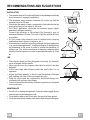
• The minimum safety distance between the cooker top and the
extractor hood is 650 mm.
• Check that the mains voltage corresponds to that indicated on the
rating plate fixed to the inside of the hood.
• For Class I appliances, check that the domestic power supply
guarantees adequate earthing.
Connect the extractor to the exhaust flue through a pipe of
minimum diameter 120 mm. The route of the flue must be as short
as possible.
• Do not connect the extractor hood to exhaust ducts carrying
combustion fumes (boilers, fireplaces, etc.).
• If the extractor is used in conjunction with non-electrical appliances
(e.g. gas burning appliances), a sufficient degree of aeration must
be guaranteed in the room in order to prevent the backflow of
exhaust gas. The kitchen must have an opening communicating
directly with the open air in order to guarantee the entry of clean
air.
USE
• The extractor hood has been designed exclusively for domestic
use to eliminate kitchen smells.
• Never use the hood for purposes other than for which it has ben
designed.
• Never leave high naked flames under the hood when it is in
operation.
• Adjust the flame intensity to direct it onto the bottom of the pan
only, making sure that it does not engulf the sides.
• Deep fat fryers must be continuously monitored during use:
overheated oil can burst into flames.
• The hood should not be used by children or persons not instructed
in its correct use.
MAINTENANCE
• Switch off or unplug the appliance from the mains supply before
carrying out any maintenance work.
• Clean and/or replace the Filters after the specified time period.
• Clean the hood using a damp cloth and a neutral liquid detergent.
650 mm min.

12GB
CHARACTERISTICS
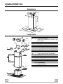
Dimensions
Components
Ref. Q.ty Product Components
1 1 Hood Body, complete with: Controls, Light,
Blower, Filters
2 1 Telescopic Chimney comprising:
2.1 1 Upper Section
2.2 1 Lower Section
9 1 Reducer Flange ø 150-120 mm
14.1 2 Air Outlet Connection Extension
15 1 Air Outlet Connection
Ref. Q.ty Installation Components
7.2.1 2 Upper Chimney Section Fixing Brackets
7.3 1 Air Outlet Connection Support
11 6 Wall Plugs
12a 6 Screws 4,2 x 44,4
12c 6 Screws 2,9 x 9,5
Q.ty Documentation
1 Instruction Manual
1 Warranty
2.1
2.2
2
12c
12a
7.2.1 11
11
12a
1
9
7.3
14.1
15
260
3
0
0
126
63
41
81
740
MIN.870-MAX.1200
6
46
420
520
5
3
0
598-898

13GB
INSTALLATION
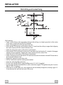
Wall drilling and bracket fixing
Wall marking:
• Draw a vertical line on the supporting wall up to the ceiling, or as high as practical, at the centre
of the area in which the hood will be installed.
• Draw a horizontal line at 650 mm above the hob.
• Place bracket 7.2.1 on the wall as shown about 1-2 mm from the ceiling or upper limit aligning
the centre (notch) with the vertical reference line.
• Mark the wall at the centres of the holes in the bracket.
• Place bracket 7.2.1 on the wall as shown at X mm below the first bracket (X = height of the upper
chimney section supplied), aligning the centre (notch) with the vertical line.
• Mark the wall at the centres of the holes in the bracket.
• Mark a reference point as indicated at 116 mm from the vertical reference line and 306 mm above
the horizontal reference line.
• Repeat this operation on the other side.
• Drill ø 8 mm holes at all the centre points marked.
• Insert the wall plugs 11 in the holes.
• Fix the lower bracket 7.2.1 using the 12a screws (4,2 x 44,4) supplied.
• Fix the upper bracket 7.2.1 and the air outlet connection support 7.3 together using the 2 screws
12a (4,2 x 44,4) supplied.
• Insert the two screws 12a (4,2 x 44,4) supplied in the hood body fixing holes, leaving a gap of 5-
6 mm between the wall and the head of the screw.
11
12a
306
X
116
1÷2
116
650 min.
7.2.1

14GB
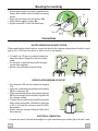
Mounting the hood body
• Before attaching the hood body, tighten the two
screws Vr located on the hood body mounting
points.
• Hook the hood body onto the screws 12a
• Fully tighten support screws 12a
• Adjust screws Vr to level the hood body.
Connections
DUCTED VERSION AIR EXHAUST SYSTEM
When installing the ducted version, connect the hood to the chimney using either a flexible or rigid
pipe ø 150 or 120 mm, the choice of which is left to the installer.
• To install a ø 120 mm air exhaust connection,
insert the reducer flange 9 on the hood body
outlet.
• Fix the pipe in position using sufficient pipe
clamps (not supplied).
• Remove any activated charcoal filters.
RECIRCULATION VERSION AIR OUTLET
• Put connection 15 into the connection support
7.3.
• Insert the connection extension pieces laterally
14.1 in connection 15.
• Make sure that the outlet of the extension pieces
14.1 is horizontally and vertically aligned with
the chimney outlets.
• Connect the air outlet connection 15 to the hood
body outlet using either a flexible or rigid pipe
ø 150 or 120 mm, the choice of which is left to
the installer.
• Ensure that the activated charcoal filters have
been inserted.
ELECTRICAL CONNECTION
• Connect the hood to the mains through a two-pole switch having a contact gap of at least 3 mm.
12a
Vr
9
ø 120ø 150
ø 150
14.1
15

15GB
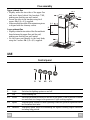
Flue assembly
Upper exhaust flue
• Slightly widen the two sides of the upper flue
and hook them behind the brackets 7.2.1,
making sure that they are well seated.
• Secure the sides to the brackets using the 4
screws 12c (2,9 x 9,5) supplied.
• Make sure that the outlet of the extensions pieces
is aligned with the chimney outlets.
Lower exhaust flue
• Slightly widen the two sides of the flue and hook
them between the upper flue and the wall,
making sure that they are well seated.
• Fix the lower part laterally to the hood body
using the 2 screws 12c (2,9 x 9,5) supplied.
USE
Control panel
L Light Switches the lighting system on and off.
S Led Motor running led.
V1 Motor Switches the extractor motor on and off at low speed. Used to provide a contin-
uos and silent air change in the presence of light cooking vapours.
V2 Speed Medium speed, suitable for most operating conditions given the optimum treated
air flox/noise level ratio.
V3 Intensive Maximum speed, used for eliminating the highest cooking vapour emission,
including long periods.
12c
2.1
2.2
2
7.2.1
12c
L
V1 V2 V3
S

16GB
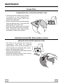
MAINTENANCE
Grease filters
CLEANING METAL SELF- SUPPORTING GREASE FILTERS
• The filters must be cleaned every 2 months
of operation, or more frequently for
particularly heavy usage, and can be
washed in a dishwasher.
• Remove the filters one at a time by pushing
them towards the back of the group and
pulling down at the same time.
• Wash the filters, taking care not to bend
them. Allow them to dry before refitting.
• When refitting the filters, make sure that
the handle is visible on the outside.
Activated charcoal filter (Recirculation version)
REPLACING THE ACTIVATED CHARCOAL FILTER
• The filter is not washable and cannot be
regenerated, and must be replaced
approximately every 4 months of operation, or
more frequently for particularly heavy usage.
• Remove the metal grease filters
• Remove the saturated activated carbon filter by
releasing the fixing hooks
• Fit the new filter by hooking it into its seating
• Replace the metal grease filters.

17GB
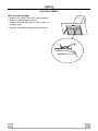
Lighting
LIGHT REPLACEMENT
40 W incandescent light.
• Remove the screw fixing the Lighting support.
• Pull the Lighting support down.
• Extract the lamp and replace with another of
the same type.
• Replace the lighting support in reverse order.

Quest’apparecchio é conforme alla norma europea sulla bassa tensione C.E.E. 73/23 relativa
alla sicurezza elettrica e alle norme europee: C.E.E. 89/336 relativa alla compatibilità elettro-
magnetica e C.E.E. 93/68 relativa alla marcatura CE.
This appliance complies with European regulations on low voltages, EEC Directive 73/23 on
electrical safety, and with the following European regulations: EEC Directive 89/336 on
electromagnetic compatibility and EEC Directive 93/68 on EC marking.
Cet équipement est conforme à la norme européenne sur la basse tension C.E.E. 73/23 relati-
ve à la sécurité électrique et aux normes européennes: C.E.E. 89/336 relative à la compatibilité
électromagnétique et C.E.E. 93/68 relative au marquage CE.
Dieses Gerät entspricht den europäischen Niederspannungsrichtlinien 73/23/EWG zur
elektrischen Sicherheit, den europäischen Richtlinien 89/336/EWG zur elektromagnetischen
Verträglichkeit und den Richtlinien 93/68/EWG zur CE-Kennzeichnung
Dit apparaat voldoet aan de Europese Laagspanningsrichtlijn 72/23/EEG inzake de elektrische
veiligheid en aan de Europese normen 89/336/EEG inzake de elektromagnetische compatibiliteit
en 93/68/EEG inzake de CE-markering.
436000715 01 020523
-
 1
1
-
 2
2
-
 3
3
-
 4
4
-
 5
5
-
 6
6
-
 7
7
-
 8
8
-
 9
9
-
 10
10


Zanussi ZHC950ALU Manuel utilisateur
- Catégorie
- Hottes
- Taper
- Manuel utilisateur
dans d''autres langues
- English: Zanussi ZHC950ALU User manual