Hoover 33801476 Manuel utilisateur
- Catégorie
- Hottes
- Taper
- Manuel utilisateur
Ce manuel convient également à

- 3 -
M
max 90 cm
20
235
Fig.4
Fig.2 Fig.3
Fig.1

- 4 -
B
C
A
Fig.8
Fig.5 Fig.7
Fig.6
Fig.9
Fig.6

- 18 -
ctionnement en cours s’acheront, de manière alternative, sur
l’écran, les ltres au charbon doivent être remplacés.
En appuyant pendant quelques secondes sur la touche “A” , la
fonction est réinitialisée.
SERVICE ASSISTANCE CLIENTS
Avant de faire appel au service d’assistance technique.
En cas de non fonctionnement du produit, nous vous con-
seillons de:
- Vérier que la che est bien enfoncée dans la prise de courant.
Si vous n’arrivez pas à identier la cause du mauvais fonction-
nement: mettez l’appareil hors tension et appelez le service
d’assistance technique. N’essayez surtout pas de le réparer
vous-même.
NUMÉRO DE SÉRIE DU PRODUIT. Où se trouve-t-il?
Il est important de communiquer au service d’assistance
technique le sigle du produit ainsi que son numéro de série
(16 caractères commençant par le chire 3) que vous trouverez
dans le certicat de garantie ou bien sur la plaque d’immatri-
culation située à l’intérieur de l’appareil.
Vous éviterez ainsi que le technicien n’eectue des déplace-
ments inutiles et économiserez par la même occasion sur les
frais correspondants.
NOUS DECLINOS TOUTE RESPONSABILI TE POUR LES
EVENTUELS DÉGATS PROVOQUÉS PAR L’INOBSERVATION
DES SUSDITES INSTRUCTIONS.
ENGLISH
GB
GENERAL
Carefully read the following important information regarding
installation safety and maintenance. Keep this information
booklet accessible for further consultations. The appliance
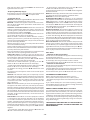
has been designed for use in the ducting version (air exhaust
to the outside - Fig.1B), filtering version (air circulation on the
inside - Fig.1A) or with external motor (Fig.1C).
SAFETY PRECAUTION
1. Take care when the cooker hood is operating simultaneously
with an open fireplace or burner that depend on the air in the
environment and are supplied by other than electrical energy,
as the cooker hood removes the air from the environment
which a burner or fireplace need for combustion. The negative
pressure in the environment must not exceed 4Pa (4x10⁻⁵ bar).
Provide adequate ventilation in the environment for a safe
operation of the cooker hood. Follow the local laws applicable
for external air evacuation.
Before connecting the model to the electricity network:
- Control the data plate (positioned inside the appliance)
to ascertain that the voltage and power correspond to the
network and the socket is suitable. If in doubt ask a qualified
electrician.
- If the power supply cable is damaged, it must be replaced with
another cable or a special assembly, which may be obtained
direct from the manufacturer or from the Technical Assistance
Centre.
- This device must be connected to the supply network through
either a plug fused 3A or hardwired to a 2 fase spur protected
by 3A fuse.
2. Warning!
In certain circumstances electrical appliances may be a
danger hazard.
A) Do not check the status of the filters while the cooker
hood is operating.
B) Do not touch bulbs or adjacent areas, during or straight
after prolonged use of the lighting installation.
C) Flambè cooking is prohibited underneath the cooker
hood.
D) Avoid free flame, as it is damaging for the filters and a
fire hazard.
E) Constantly check food frying to avoid that the
overheated oil may become a fire hazard.
F) Disconnect the electrical plug prior to any maintenance.
G) This appliance is not intended for use by young children
or infirm persons without supervision.
H) Young children should be supervised to ensure they do
not play with the appliance.
I) There shall be adequate ventilation of the room when
the rangehood is used at the same time as appliances
burning gas or other fuels.
L) There is a risk of fire if cleaning is not carried out in
accordance with the instructions.
This appliance conforms to the European Directive EC/2002/96,
Waste Electrical and Electronic Equipment (WEEE). By making
sure that this appliance is disposed of in a suitable manner,
the user is helping to prevent potential damage to the
environment or to public health.
The symbol on the product or on the accompanying
paperwork indicates that the appliance should not be
treated as domestic waste, but should be delivered to
a suitable electric and electronic appliance recycling collection
point. Follow local guidelines when disposing of waste. For
more information on the treatment, re-use and recycling of
this product, please contact your local authority, domestic
waste collection service or the shop where the appliance was
purchased.
INSTALLATION INSTRUCTIONS
•Assemblyandelectricalconnectionsmustbecarriedout
by specialised personnel.
•Wearprotectiveglovesbeforeproceedingwith the
installation.
•ElectricConnection:
Note! Verify the data label placed inside the appliance:
- If the symbol
appears on the plate, it means that no earth
connection must be made on the appliance, therefore follow
the instructions concerning insulation class II.
- If the symbol
DOES NOT appear on the plate, follow the
instructions concerning insulation class I.
Insulation class II
- The appliance has been manufactured as a class II, therefore
no earth cable is necessary. The plug must be easily accessible
after the installation of the appliance. If the appliance
is equipped with power cord without plug, a suitably
dimensioned omnipolar switch with 3 mm minimum opening
between contacts must be fitted between the appliance and
the electricity supply in compliance with the load and current
regulations.
- The connection to the mains is carried out as follows:
BROWN = L line
BLUE = N neutral.

- 19 -
Insulation class I
This is a class I, appliance and must therefore be connected to
an effiecient earthing system.
- The appliance must be connected to the electricity supply as
follows:
BROWN = L line
BLUE = N neutral
YELLOW/GREEN =
earth.
The neutral wire must be connected to the terminal with the
N symbol while the YELLOW/GREEN, wire must be connected
to the terminal by the earth symbol .
When connecting the appliance to the electricity supply, make
sure that the mains socket has an earth connection. After fitting
the ducted cooker hood, make sure that the electrical plug is
in a position where it can be accessed easily. If the appliance
is connected directly to the electricity supply, an omnipolar
switch with a minimum contact opening of 3 mm must be
placed in between the two; its size must be suitable for the
load required and it must comply with current legislation.
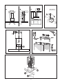
• If the hob is electric, gas, or induction, the minimum distance
between the same and the lower part of the hood must be at
least 65 cm. If a connection tube composed of two parts is
used, the upper part must be placed outside the lower part. Do
not connect the cooker hood exhaust to the same conductor
used to circulate hot air or for evacuating fumes from other
appliances generated by other than an electrical source. Before
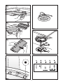
proceeding with the assembly operations, remove the anti-
grease filter(s) (Fig.5A) so that the unit is easier to handle.
- In the case of assembly of the appliance in the suction version
prepare the hole for evacuation of the air.
• We recommend the use of an air exhaust tube which has the
same diameter as the air exhaust outlet hole. If a pipe with a
smaller diameter is used, the efficiency of the product may be
reduced and its operation may become noisier.
•Fixingtothewall:
- Drill the holes A respecting the distances indicated (Fig.2).
- Fix the appliance to the wall and align it in horizontal position
to the wall units.
- When the appliance has been adjusted, definitely fix the hood
using the screws A (Fig.4).
For the various installations use screws and screw anchors
suited to the type of wall (e.g. reinforced concrete, plasterboard,
etc.). If the screws and screw anchors are provided with the
product, check that they are suitable for the type of wall on
which the hood is to be fixed.
•Fixingthedecorativetelescopicflue:
- Arrange the electrical power supply within the dimensions
of the decorative flue. If your appliance is to be installed in the
ducting version or in the version with external motor, prepare
the air exhaust opening.
- Adjust the width of the support bracket of the upper flue
(Fig.3).
- Then fix it to the ceiling using the screws A (Fig.3) in such a
way that it is in line with your hood and respecting the distance
from the ceiling indicated in Fig.2.
- Connect the flange C to the air exhaust hole using a
connection pipe (Fig.4).
- Insert the upper flue into the lower flue.
- Fix the lower flue to the hood using the screws B provided
(Fig.4), extract the upper flue up to the bracket and fix it with
the screws B (Fig.3).
To transform the hood from a ducting version into a filtering
version, ask your dealer for the charcoal filters and follow the
installation instructions.
•Filterhood:
Please note:
- In order to transform the hood from EXTRACTOR HOOD into
FILTER HOOD the active carbon filters must be ordered at your
distributor as accessory.
We have two different types of Kit, one with non-regenerable
active carbon filters (Fig.5B) and the other one with
regenerable active charcoal filters (washable) (Fig.5C).
- To replace the non-regenerable active carbon filters X, pull
lever outwards as shown in Fig.5B.
USE AND MAINTENANCE
• We recommend that the cooker hood is switched on before
any food is cooked. We also recommend that the appliance is
left running for 15 minutes after the food is cooked, in order
to thoroughly eliminate all contaminated air. The effective
performance of the cooker hood depends on constant
maintenance; the anti-grease filter and the active carbon filter
both require special attention.
•Theanti-greasefilter is responsible retaining the grease
particles suspended in the air, therefore it is subject to clogging
with variable frequency according to the use of the appliance.
- To prevent the danger of possible fires, at least every 2
months one must wash the anti-grease filters by hand using
non-abrasive neutral liquid detergents or in the dishwasher
at low temperatures and on short cycles.
- After a few washes, colour alterations may occur. This does
not give the right to claim their replacement.
•Theactivecarbonfilters are used to purify the air that is
sent back into the room and its function is to mitigate the
unpleasant odours produced by cooking.
- The non-regenerable active carbon filters must be replaced
at least every 4 months. The saturation of the active charcoal
depends on the more or less prolonged use of the appliance,
on the type of kitchen and on the frequency with which anti-
grease filter is cleaned.
- Regenerable active charcoal filters must be washed by hand,
with non abrasive neutral detergents, or in the dishwasher at
a maximum temperature of 65°C (the washing cycle must be
complete without dishware). Remove excess water without
damaging the filter, remove the plastic parts, and let the
mat dry in the oven for at least 15 minutes approximately at
a maximum temperature of 100°C. To keep the regenerable
charcoal filter functioning efficient this operation must be
repeated every 2 months. These must be replaced at least
every 3 years or when the mat is damaged.
•Beforeremountingtheanti-greasefiltersand the
regenerable active charcoal filters it is important that they
are completely dry.
•Cleanthehoodfrequently,bothinternallyandexternally,
using a cloth dampened with denatured alcohol or neutral
liquid detergents that are non abrasive.
• The lighting .system is designed for use during cooking
and not for the prolonged general lighting of the room. The
prolonged use of the lighting system significantly decreases
the average duration of the bulbs.
• If the appliance is equipped with courtesy lights it is possible
to use them for general room lighting for a prolonged amount
of time.
•Attention: the non compliance with the hood cleaning
warnings and with the replacement and cleaning of the filters
entails risk of fires. One therefore recommends keeping to the
suggested instructions.
•Replacinghalogenlightbulbs(Fig.7):
To replace the halogen light bulbs B, remove the glass pane
C using a lever action on the relevant cracks. Replace the bulbs

- 20 -
with new ones of the same type. Caution: do not touch the
light bulb with bare hands.
•ReplacingLEDlamps(Fig.6):
If the appliance version is with LED lamps, the intervention of
a specialised technician is necessary to replace them.
•Commands(Fig.9):
Button A = Switches the lights On/O. The “lter alarm” can be
reset by pressing the button for a few seconds.
Button B = Switches the appliance on/Decreases the extrac-
tion rate of the motor. If the speed of the cooker hood is set
to 1, it switches o.
Automaticextraction function: With this function the
appliance automatically adjusts the motor’s extraction rate
according to the quality of the air below thanks to the sensor
located under the cooker hood (Fig.8).
To activate this function, press the “B” button for a few secon-
ds. The letter “S“ will appear on the display.
When the hood is switched on, before automatic suction is
enabled, you must wait a period of time depending on the
sensor's type of setting. When this is not yet active, the decimal
point on the display will ash.
When the function is active, the suction power of the motor
cannot be modied manually.
At the end of the motor's operating cycle, with the automatic
function active, if the hood does not re-start within 10 minutes
it will be permanently switched o.
This same situation occurs if the function is activated and the
motor does not start operating within 10 minutes.
Setting the sensor: According to the type of hob (gas or
electric) it is possible to increase the eectiveness of the sensor
by matching the cooker hood with the right hob.
To carry out this operation, press the “B” and “D” buttons
together for a few seconds with the motor o.
- To match the cooker hood with a gas hob, press the “B“
button. A “P” and a “0” will alternate on the display.
- To match the cooker hood with an electric hob, press the “D“
button. A “P” and a “1” will alternate on the display.
To complete the setting, press the “B+D” buttons for a few
seconds.
The appliance has already been set for an electric hob by the
manufacturer.
Intensive: This function allows you to temporarily increase
the motor’s extraction rate for about 6 minutes. To activate the
function, press the “D“ button after selecting extraction rate
level 3. After 6 minutes, the appliance will return to operate
at extraction rate level 3. During this function the letter "P"
will be displayed.
Timer: This function allows you to set the operating time of
the appliance to about 15 minutes, even if the speed is modi-
ed later, which then switches o at the end. To activate the
function press the “E” button; the decimal point on the display
will start to ash. The timer and the intensive function cannot
be activated at the same time. The timer does not interact with
the lights. To deactivate the function, set the extraction rate
level back to “0”.
Carbon lter: Carbon lters are used to purify the air which
is released back into the room. The lters are not washable
or re-usable and must be replaced at least once every four
months. Saturation levels of carbon lters depend on the fre-
quency with which the appliance is used, the type of cooking
performed and how often the anti-grease lters are cleaned.
To activate the lter alarm function, press the “A+E“ buttons
together.
- To activate the carbon lter alarm, press the “D“ button. An
“A” and a “1”will alternate on the display.
- To deactivate the carbon lter alarm, press the “B“ button.
An “A” and a “0” will alternate on the display.
To deactivate this function, press the “A+E“ buttons together
with the motor o.
Button C = The display shows the extraction rate of the motor
and all the functions of the buttons mentioned above.
Button D = Increases the motor speed.
Enabling/disabling WiFi: The appliance can be controlled
remotely with external devices. To enable the function press
"D+E" buttons for 3 seconds. "0" will be displayed and the
"Read only" function is active. If "D+E" buttons are pressed for
6 seconds, the "write" function is activated and "1" is displayed.
If the WiFi module has to be Reset, press "D+E" for at least 10
seconds; "R" will be displayed.
Monitoring function: This function allows the appliance to
monitor the environment for an indenite time. In case of
sudden variations in the status of the air or unexpected com-
bustions, the hood will send to the connected external devices
an alarm and a ashing "A" will be displayed. To activate the
function keep "E" pressed and three horizontal lines will be di-
splayed. A decimal point will ash until the sensor is stabilised.
Press any key to deactivate the function.
Deterrent function: This function simulates the presence of
people in the residence. The appliance will switch the lights
on and o with cyclic repetitions (lights on for 25 minutes and
lights o for 5 minutes). To activate the function press "D" for 5
seconds with the hood o. Two vertical lines will be displayed.
Press any key to deactivate the function.
Filter Alarm:
•SaturationofAnti-greaseFilters:
This function is activated after the appliance has been running
for approximately 30 hours.
The letter “F” and the current extraction rate level will alternate
on the display. The anti-grease lters must be cleaned.
To reset the function, press the “A” button for a few seconds.
•SaturationofCarbonFilters:
This function is activated after the appliance has been running
for approximately 120 hours.
The letter “A” and the current extraction rate level will alternate
on the display. The carbon lters must be replaced.
To reset the function, press the “A” button for a few seconds.
CUSTOMER ASSISTANCE SERVICE
Before contacting the Technical Assistance Service.
If the product does not operate at all, we advise you to:
- Check that the plug has been inserted into the power socket
correctly.
If you cannot identify the cause of the operating anomaly:
switch o the appliance (do not subject it to rough treatment)
and contact the Assistance Service.
PRODUCT SERIAL NUMBER. Where can I nd it?
It is important that you inform the Assistance Service of your
product code and its serial number (a 16-character code which
begins with the number 3); this can be found on the guarantee
certicate or on the data plate located inside the appliance.
This will help to avoid wasted journeys being made by techni-
cians, thereby (and most signicantly) saving the correspon-
ding callout charges.
THE MANUFACTURER DECLINES ALL RESPONSIBILITY
FOR EVENTUAL DAMAGES CAUSED BY BREACHING THE
ABOVE WARNINGS.
-
 1
1
-
 2
2
-
 3
3
-
 4
4
-
 5
5


Hoover 33801476 Manuel utilisateur
- Catégorie
- Hottes
- Taper
- Manuel utilisateur
- Ce manuel convient également à
dans d''autres langues
- English: Hoover 33801476 User manual