Toro CCR 2000 Snowthrower Manuel utilisateur
- Catégorie
- Souffleuses à neige
- Taper
- Manuel utilisateur

Operator’s Manual
Manuel de l’Utilisateur
FORM NO. 3317–758 Rev. A
CCR 2000
Snowthrower
Model No. 38181 – 6900001 & Up
Model No. 38186 – 6900001 & Up
CCR 2000
Déneigeuse
Modèle No. 38181 – 6900001 et suivants
Modèle No. 38186 – 6900001 et suivants

The Toro Company – 1995
All Rights Reserved
Printed in USA
i
Figures
637
1
English
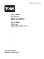
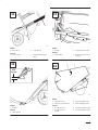
1. Model and serial number decal
Français
1. Décalcomanie de numéros de modèle et de série
637
1
2
3
English
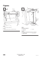
(Unit shown on right side)
1. Short spacer
2. Long spacer
3. Pushnut
Français
(La déneigeuse est montrée basculée sur son côté droit)
1. Entretoise courte
2. Entretoise longue
3. Ecrou–poussoir
1 2

ii
635/893
1
3
2
English
1. Chute crank
2. Mounting bracket
3. Gear
Français
1. Tige de commande de
l’éjecteur
2. Support de montage
3. Engrenage
636
2
1
English
1. Chute ring 2. Discharge chute
Français
1. Couronne de l’éjecteur 2. Ejecteur
633
4
1
2
3
English
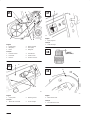
1. Lower handle
2. Upper handle
3. Handle bolt
4. Eyebolt
Français
1. Mancheron inférieur
2. Mancheron supérieur
3. Boulon du mancheron
4. Boulon à oeil
625
3
2
1
1/16”-1/8”
1,59-3,18 mm
English
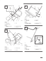
1. Eyebolt
2. Control bar bracket
3. Rear hole
Français
1. Boulon à oeil
2. Orifice arrière
3. Support de la barre de
commande
3
4
5
6

iii
111
1
2
3
English
1. Add oil to small amount of
gasoline
2. Install cap and shake can
to mix
3. Add remaining amount of
gasoline
Français
1. Versez l’huile dans une
petite quantité d’essence
2. Mettez le bouchon et
secouez bien pour
mélanger
3. Ajoutez le reste de
l’essence
642
6
5
3
21
4
English
1. Key switch
2. Primer
3. Recoil start
4. Choke
5. Elec. start button*
6. Cord connection*
* ELEC. START MODEL
Français
1. Clé d’allumage
2. Amorceur
3. Démarreur à rappel
4. Etrangleur
5. Bouton du démarreur
électrique*
6. Raccord du cordon*
* MODELE A
DEMARRAGE
ELECTRIQUE
629
3
2
1
English
1. Chute crank
2. Chute deflector handle
3. Deflector mounting nuts
Français
1. Tige de commande de
l’éjecteur
2. Mancheron du déflecteur
de l’éjecteur
3. Ecrous de montage du
déflecteur
625
3
2
1
1/16”-1/8”
1,59-3,18 mm
English
1. Eyebolt
2. Control bar bracket
3. Rear hole
Français
1. Boulon à oeil
2. Orifice arrière
3. Support de la barre de
commande
7
8
9
10

iv
630
2
1
English
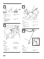
1. Spring cover 2. Cable adjuster
Français
1. Cache–ressort 2. Dispositif de réglage du
câble
634
1/16”
1
1,6 mm
English
1. Scraper
Français
1. Lame racleuse
644
1
2
English
1. Scraper 2. Carriage bolts & locknuts
Français
1. Lame racleuse 2. Boulons japy et écrous de
blocage
631
3
2
1
4
English
1. Capscrew and nut
2. Capscrew, nut and washer
3. Long self tapping screw
4. Short self tapping screw
Français
1. Vis à tête et écrou
2. Vis à tête, écrou et
rondelle
3. Vis autotaraudeuse longue
4. Vis autotaraudeuse courte
11
12
13
14

v
6
2
6
2
4
1
63
5
English
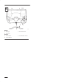
1. Engine pulley
2. Idler pulley
3. Roller
4. Brake assembly
5. Rotor pulley
6. Belt guide
Français
1. Poulie du moteur
2. Poulie folle
3. Rouleau
4. Unité de frein
5. Poulie du rotor
6. Guide de courroie
643
1
2
English
1. Control panel 2. Mounting screws
Français
1. Tableau de commande 2. Vis de montage
628
1
English
1. Spark plug wire
Français
1. Câble de bougie
110
0.032”
(0,813 mm)
716
1
English
1. Wear indicator hole
Français
1. Trou indicateur d’usure
15
16
17
18
19

vi
680
1
6
4
7
4
5
8
2
3
English
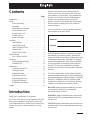
1. Rotor blade (2)
2. Rotor half (2)
3. Torx screw (8)
4. Locknut (13)
5. Hex-head capscrew (4)
6. Spacer (4)
7. Auger shaft assembly
8. Hex-head screw
Français
1. Lame du rotor (2)
2. Plaques d’acier
3. Vis Torx (8)
4. Ecrou de blocage (13)
5. Vis à tête hexagonale (4)
6. Entretoise (4)
7. Arbre de la tarière
8. Vis à tête hexagonale
20

vii
6812
1
3
English
1. Thin layer
2. Thick layer
3. Wear indicator hole
Français
1. Couche mince
2. Couche épaisse
3. Trou Indicateur d’usure
21

GB–1
Contents
Page
Introduction 1. . . . . . . . . . . . . . . . . . . . . . . . . . . .
Safety 2. . . . . . . . . . . . . . . . . . . . . . . . . . . . . . . . .
Before Operating 2. . . . . . . . . . . . . . . . . . . .
Operating 2. . . . . . . . . . . . . . . . . . . . . . . . . .
Maintenance and Storage 3. . . . . . . . . . . . . .
Sound Pressure Level 3. . . . . . . . . . . . . . . . .
Sound Power Level 3. . . . . . . . . . . . . . . . . .
Vibration Level 3. . . . . . . . . . . . . . . . . . . . . .
Symbol Glossary 4. . . . . . . . . . . . . . . . . . . .
Assembly 7. . . . . . . . . . . . . . . . . . . . . . . . . . . . . .
Install Wheels 7. . . . . . . . . . . . . . . . . . . . . . .
Install Chute Crank 7. . . . . . . . . . . . . . . . . .
Install Discharge Chute 8. . . . . . . . . . . . . . .
Install Handle 8. . . . . . . . . . . . . . . . . . . . . . .
Install Control Cable 8. . . . . . . . . . . . . . . . .
Before Starting 8. . . . . . . . . . . . . . . . . . . . . . . . . .
Mix Gasoline And Oil 8. . . . . . . . . . . . . . . .
Operation 9. . . . . . . . . . . . . . . . . . . . . . . . . . . . . .
Starting/Stopping Engine 9. . . . . . . . . . . . . .
Operating Tips 10. . . . . . . . . . . . . . . . . . . . . .
Maintenance 11. . . . . . . . . . . . . . . . . . . . . . . . . . . .
Adjusting Control Bar 11. . . . . . . . . . . . . . . .
Draining Gasoline 11. . . . . . . . . . . . . . . . . . .
Replacing Scraper 11. . . . . . . . . . . . . . . . . . .
Replacing Drive Belt 11. . . . . . . . . . . . . . . . .
Replacing Spark Plug 12. . . . . . . . . . . . . . . . .
Adjusting Carburetor 12. . . . . . . . . . . . . . . . .
Replacing Rotor Blades 12. . . . . . . . . . . . . . .
Storage 13. . . . . . . . . . . . . . . . . . . . . . . . . . . . . . . .
Introduction
Thank you for purchasing a Toro product.
All of us at Toro want you to be completely satisfied
with your new product, so feel free to contact your
local Authorized Service Dealer for help with service,
genuine Toro parts, or other information you may
require.
Whenever you contact your Authorized Service
Dealer or the factory, always know the model and
serial numbers of your product. These numbers will
help the Service Dealer or Service Representative
provide exact information about your specific
product. You will find the model and serial number
decal located in a unique place on the product as
shown in Figure 1.
For your convenience, write the product model and
serial numbers in the space below.
Model No:
Serial No.
Read this manual carefully to learn how to operate
and maintain your product correctly. Reading this
manual will help you and others avoid personal injury
and damage to the product. Although Toro designs,
produces and markets safe, state-of-the-art products,
you are responsible for using the product properly
and safely. You are also responsible for training
persons who you allow to use the product about safe
operation.
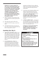
The Toro warning system in this manual identifies
potential hazards and has special safety messages that
help you and others avoid personal injury, even death.
DANGER, WARNING and CAUTION are signal
words used to identify the level of hazard. However,
regardless of the hazard, be extremely careful.
DANGER signals an extreme hazard that will cause
serious injury or death if the recommended
precautions are not followed.
WARNING signals a hazard that may cause serious
injury or death if the recommended precautions are
not followed.
CAUTION signals a hazard that may cause minor or
moderate injury if the recommended precautions are
not followed.

GB–2
Two other words are also used to highlight
information. “Important” calls attention to special
mechanical information and “Note” emphasizes
general information worthy of special attention.
The left and right side of the machine is determined
by standing behind the handle in the normal
operator’s position.
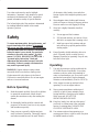
Safety
To ensure maximum safety, best performance, and
to gain knowledge of the product, it is essential
that you or any other operator of the snowthrower
read and understand the contents of this manual
before the motor is ever started. Pay particular
attention to the safety alert symbol
which
means CAUTION, WARNING OR DANGER —
“personal safety instruction.” Read and
understand the instruction because it has to do
with safety. Failure to comply with instruction
may result in personal injury.
WARNING: Engine exhaust contains carbon
monoxide which is an odorless, deadly poison.
Carbon monoxide is also known to the State of
California to cause birth defects. Do not run engine
indoors or in an enclosed area.
Before Operating
1. Read this manual carefully. Never allow children
to operate the snowthrower. Adults should
operate the snowthrower only after reading this
manual.
2. Be thoroughly familiar with the controls and
proper use of the unit. Know how to stop engine
and snowthrower quickly.
3. Keep everyone, especially children and pets,
away from area of operation. Thoroughly inspect
area where snowthrower will be used. Remove
all doormats, sleds, boards, wires and other
foreign objects which might be picked up and
thrown.
4. Wear adequate winter clothing and footwear
which will improve footing on slippery surfaces.
Exercise caution to avoid slipping or falling.
5. Since fuel is highly flammable, handle it
carefully.
A. Use an approved fuel container.
B. Fill fuel tank outdoors, not indoors. Never
add fuel to an engine that is running or hot.
C. Install gas cap on fuel container and gas
tank, and wipe up spilled gasoline before
starting engine.
6. Keep all guards, shields and safety devices in
place. If a guard, shield, or safety device is
damaged, repair before operating. Keep all nuts,
bolts and screws tight.
Operating
7. Use only the extension cord provided with the
CCR 2000 Electric Start Model. Do not plug
extension cord into outlet while standing in
water or when hands are wet. Do not use cord if
gasoline has been spilled. Replace damaged
extension cord immediately (Part No. 28-9170).
8. Allow engine to warm up outdoors before
operating. Do not run engine indoors.
9. Never operate snowthrower without good
visibility or light. Always maintain secure
footing and keep a firm grip on the handles.
Walk; never run. DO NOT USE
SNOWTHROWER ON ROOF.
10. Keep face, hands, feet, and any other part of
your body or clothing away from concealed,
moving, or rotating parts. ALWAYS STAY
CLEAR OF DISCHARGE AREA.
11. Use extreme caution when operating on or
crossing gravel drives, walks or roads. Stay alert
for hidden hazards or traffic.

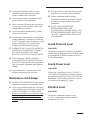
GB–3
12. Never direct discharge toward or operate
snowthrower near glass enclosures, motor
vehicles, window wells or drop-offs.
13. Never direct discharge at bystanders or allow
anyone in front of the snowthrower.
14. Never clear snow off steep slopes or across the
face of slopes. Exercise extreme caution when
changing direction on slopes.
15. Do not overload the snowthrower by clearing
snow at too fast a rate.
16. After striking a foreign object or if snowthrower
vibrates abnormally, stop engine by turning key
to OFF. Thoroughly inspect snowthrower for any
damage, obstruction or loose parts. Repair
damage before restarting and operating.
17. WHENEVER YOU LEAVE THE OPERATING
POSITION, STOP ENGINE BY TURNING
KEY TO OFF. REMOVE KEY FROM
SWITCH IF UNIT WILL BE UNATTENDED.
18. Before inspecting, adjusting, repairing or
cleaning snowthrower, stop engine by turning
key to OFF. Always wait for all moving parts to
stop. Do not make adjustments while engine is
running.
19. After clearing snow, let engine run for a few
minutes so moving parts do not freeze.
Maintenance and Storage
20. REMOVE KEY FROM SWITCH when storing
snowthrower. Store key in a memorable place.
21. Never store snowthrower with fuel in fuel tank
inside a building where open flame or sparks are
present. Allow engine to cool before storing.
Never store snowthrower in house (living area)
or basement because gasoline and fumes are
highly flammable, explosive, and dangerous if
inhaled.
22. Keep all nuts, bolts, and screws tight to ensure
snowthrower is in proper working condition.
23. Perform maintenance and use storage
instructions described in this manual. Reinstall
fuel tank cap if upper shroud is removed for
maintenance.
24. ALWAYS USE GENUINE TORO
REPLACEMENT PARTS AND
ACCESSORIES TO ASSURE SAFETY AND
OPTIMUM PERFORMANCE. NEVER USE
“WILL FIT” REPLACEMENT PARTS AND
ACCESSORIES.
Sound Pressure Level
Model 38181
This unit has an equivalent continuous A-weighted
sound pressure at the operator ear of: 89 dB(A), based
on measurements of identical machines per ANSI
B71.5-1984 procedures.
Sound Power Level
Model 38181
This unit has a sound power level of: 101 dB(A) /
1 pW, based on measurements of identical machines
per procedures outlined in Directive 79/113/EEC and
amendments. The test surface consisted of a surface
of coconut mat surrounded by 2” grass.
Vibration Level
Model 38181
This unit has a maximum vibration level of
11.3 m/s, based on measurement of identical
machines per ISO 5349.

GB–4
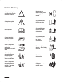
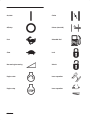
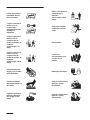
Symbol Glossary
Safety alert triangle —
symbol within triangle
indicates a hazard
Do not open or
remove safety shields
while engine is
running
Safety alert symbol
Stay a safe distance
from the machine
Read operator’s
manual
Stay a safe distance
from the machine –
single stage
snowthrower
Consult technical
manual for proper
service procedures
Stay a safe distance
from the machine –
two stage
snowthrower
Shut off engine and
remove key before
performing
maintenance or repair
work
Thrown or flying
objects — Whole body
exposure
Shut off engine and
remove key before
leaving operator
position – single
stage snowthrower
Electrical shock –
electrocution
Shut off engine and
remove key before
leaving operator
position – two stage
snowthrower
Cutting or
entanglement of foot –
rotating auger

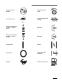
GB–5
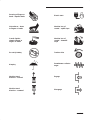
Severing of fingers or
hand – impeller blade
Electric start
Hot surfaces – burns
to fingers or hands
Machine loss of
control – uphill slope
Caustic liquids –
chemical burns to
fingers or hands
Machine loss of
control – downhill
slope
Do not tip battery Traction drive
Keep dry
Snowthrower collector
auger
Machine travel
direction – forward
Engage
Machine travel
direction – rearward
Disengage

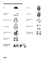
GB–6
On/start Choke
Off/stop Primer (start aid)
Fast Unleaded fuel
Slow Lock
Decreasing/Increasing Unlock
Engine start Lever operation
Engine stop Lever operation

GB–7
Snowthrower chute
direction
Throttle operation
Primer operation
PowerShift operation
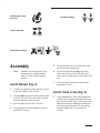
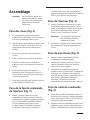
Assembly
Note: Determine left and right sides of the
snowthrower by standing behind it
while it is in the normal operating
position.
Install Wheels (Fig. 2)
1. Carefully turn machine onto its left side. Place a
wood block under the left axle end.
2. Slide the short spacer and a wheel onto the right
axle end. The side of the wheel with six spokes
must face the center of the machine.
3. Slide a pushnut onto the end of the axle.
4. Using a hammer, strike the pushnut to seat the
nut FIRMLY in place.
5. Turn the machine over on its right side so that
the left axle end is pointing up.
6. For the left side, slide the long spacer and a
wheel onto the left axle end. The side of the
wheel with six spokes must face the center of the
axle.
7. Place a wood block under the right axle end.
Repeat steps 3 and 4.
Install Chute Crank (Fig. 3)
1. Insert flattened end of chute crank through hole
in shroud while aligning mounting bracket with
holes in lower handle. Slowly rotate crank until
flattened end fits into hidden gear opening and
chute ring turns with crank. Secure mounting
bracket to handle with (2) capscrews and
locknuts.

GB–8
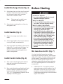
Install Discharge Chute (Fig. 4)
1. Set discharge chute onto chute ring. Secure back
of chute to center hole in ring with a carriage
bolt and sems locknut, but do not tighten.
Position nut on outside of chute.
Note: Chute ring may be rotated to ease
assembly of discharge chute.
2. Secure chute to remaining holes in chute ring
and tighten all nuts.
Install Handle (Fig. 5)
1. Remove tie securing control cable to lower
handle.
2. Position upper handle so that curved control bar
is on top of handle, not underneath it.
3. Secure upper and lower handles in place with (3)
handle bolts, (1) eyebolt, and (4) locknuts. Use
eyebolt to mount lower left side of handle.
Eyebolt must be positioned perpendicular to
handle when tightened.
Install Control Cable (Fig. 6)
1. Route control cable through eyebolt and hook
upper end in rear hole (hole with arrow) in
control bar bracket.
2. Move control bar back toward handle until slack
in cable is removed. Gap between control bar
bracket and handle should be approximately
1/16”–1/8”. If an adjustment is required, refer to
Adjusting Control Bar, page 11.
Before Starting
POTENTIAL HAZARD
• In certain conditions gasoline is extremely
flammable and highly explosive.
WHAT CAN HAPPEN
• A fire or explosion from gasoline can burn
you, others, and cause property damage.
HOW TO AVOID THE HAZARD
• Use a funnel and fill the fuel tank outdoors,
in an open area, when the engine is cold.
Wipe up any gasoline that spills.
• Do not fill the fuel tank completely full.
Add gasoline to the fuel tank until the level
is 1/4” to 1/2” (6 mm to 13 mm) below the
bottom of the filler neck. This empty space
in the tank allows gasoline to expand.
• Never smoke when handling gasoline, and
stay away from an open flame or where
gasoline fumes may be ignited by a spark.
• Store gasoline in an approved container
and keep it out of the reach of children.
• Never buy more than a 30-day supply of
gasoline.
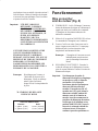
Mix Gasoline And Oil (Fig. 7)
Use clean, fresh lead-free gasoline, including
oxygenated or reformulated gasoline, with an octane
rating of 85 or higher. To ensure freshness, purchase
only the quantity of gasoline that can be used in 30
days. Use of lead-free gasoline results in fewer
combustion chamber deposits and longer spark plug
life. Use of premium grade fuel is not necessary or
recommended.
1. APPROVED OIL—For simplicity and best
engine performance, mix the contents of one 5.2
ounce bottle of Toro 50:1 Two–Cycle Oil with
two gallons of fresh, unleaded regular gasoline.
Leaded regular gasoline may be used if unleaded
regular is not available.

GB–9
Toro Two–Cycle Oil is specially formulated to
provide superior lubrication, make starting easy,
and prolong engine life. If Toro Two–Cycle Oil
is not available, mix two gallons of gasoline and
5.2 ounces of another high grade two–cycle oil
that has the NMMA or BIA–TCW certification
printed on the label.
IMPORTANT: YOU CAN ALSO USE TORO
“EASY–MIX” TWO–CYCLE OIL (3.2 OUNCE
BOTTLE MIXED ONE PER GALLON OF
GASOLINE; 40:1 RATIO) IN THIS TORO
TWO–CYCLE ENGINE.
NEVER USE AUTOMOTIVE OIL (i.e. SAE
30, 10W30 etc.), TWO–CYCLE OIL THAT IS
NOT CERTIFIED NMMA/BIA–TCW, OR THE
WRONG MIX RATIO BECAUSE THE
ENGINE CAN BE DAMAGED, AND IT
WOULD NOT BE COVERED BY THE TORO
WARRANTY.
2. Mixing Gasoline and Oil—Pour a half gallon of
gasoline into an approved gasoline container
(preferably plastic, not metal) and add the correct
amount of two–cycle oil. Install cap on gasoline
container and shake the container to mix oil and
gas thoroughly. Remove cap and add remaining
amount of gasoline.
Toro also recommends that Toro
Stabilizer/Conditioner be used regularly in all
Toro gasoline powered products during operation
and storage seasons. Toro Stabilizer/Conditioner
cleans the engine during operation and prevents
gum–like varnish deposits from forming in the
engine during periods of storage.
IMPORTANT: NEVER USE METHANOL
,
GASOLINE CONTAINING METHANOL,
GASOHOL CONTAINING MORE THAN
10% ETHANOL, PREMIUM GASOLINE,
OR WHITE GAS BECAUSE ENGINE
FUEL SYSTEM DAMAGE COULD
RESULT.
DO NOT USE FUEL ADDITIVES OTHER
THAN THOSE MANUFACTURED FOR
FUEL STABILIZATION DURING
STORAGE SUCH AS TORO’S
STABILIZER/CONDITIONER OR A
SIMILAR PRODUCT. TORO’S
STABILIZER/CONDITIONER IS A
PETROLEUM DISTILLATE BASED
CONDITIONER/STABILIZER. TORO
DOES NOT RECOMMEND STABILIZERS
WITH AN ALCOHOL BASE SUCH AS
ETHANOL, METHANOL OR ISOPROPYL.
ADDITIVES SHOULD NOT BE USED TO
TRY TO ENHANCE THE POWER OR
PERFORMANCE OF MACHINE.
Note: Do not mix gasoline and oil in the
product fuel tank. Oil that is at room
temperature mixes easier and more
thoroughly than cold oil.
50:1 GAS/OIL Mixing Chart
U.S. GALLON
Gasoline Oil
1 gallon 2.6 oz.
1.5 gallons 3.9 oz.
2 gallons 5.2 oz.
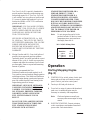
Operation
Starting/Stopping Engine
(Fig. 8)
1. CONTROLS–Key switch, primer, electric start
button and recoil start are located on control
panel. Choke is just below control panel.
2. Turn key to ON and pull choke out.
3. Cover hole in center of primer with thumb and
push once. An additional prime may be
necessary in extremely cold temperatures.
Note: Choke and primer are usually not
necessary when warm engine is being
started.
4. ELECTRIC STARTING–Connect extension
cord to snowthrower and standard household
power outlet. Push starter button.

GB–10
IMPORTANT: Excessive running of the
electric starter could damage the starter due
to overheating. To prevent possible damage,
do not run electric starter more than 10 times
at intervals of 5 seconds ON, 5 seconds OFF.
Then wait more than 40 minutes before
continuing to run starter to allow starter to
cool. Before repeating engine starting
procedure, check that ignition key switch is
ON, and make sure there is fresh fuel in fuel
tank. If engine continues to fail to start,
servicing may be needed.
5. RECOIL STARTING–Hold snowthrower with
one hand and pull recoil starter vigorously with
other hand.
6. When engine starts, push in choke slowly.
7. TO ENGAGE ROTOR–Squeeze control bar to
handle.
8. TO STOP ENGINE–Release control bar, turn
key to OFF, and wait for all moving parts to stop
before leaving operator’s position.
Operating Tips (Fig. 9)
1. ADJUSTING DISCHARGE CHUTE–Rotate
chute crank clockwise to move discharge chute
to the right and counterclockwise to move chute
to the left. Deflector handle on top of discharge
chute is used to control the height of the snow
stream. Do not overtighten deflector mounting
nuts so excessive force is required to operate
deflector.
2. SELF–PROPELLING ACTION–The
snowthrower clears down to the ground and
propels itself forward when the rotor blades
strike the ground. The wheels do not have to
touch the ground in order to self-propel. The
further you tilt the handle forward, the faster the
snowthrower self-propels. However, depth and
height of snow will affect forward speed. Always
overlap each swath and discharge downwind
when possible.
3. In some snow and cold weather conditions, some
controls and moving parts may freeze solid.
Therefore, when any control becomes hard to
operate, stop the engine; then check all parts for
excessive freeze up. DO NOT USE
EXCESSIVE FORCE WHEN TRYING TO
OPERATE THE CONTROLS IF FROZEN.
Free all controls and moving parts before
operating.
4. AFTER CLEARING SNOW — Let engine run
for a few minutes so ice does not freeze moving
parts solid. After engine is shut off, wipe ice and
snow off entire unit. Operate chute crank several
times to clear mechanism of snow.
IMPORTANT: STORE SNOWTHROWER
IN OPERATING POSITION ON ITS
WHEELS. TIPPING OR STORING UNIT
ON ITS NOSE MAY CAUSE HARD
STARTING.
POTENTIAL HAZARD
• When engine is running, discharge rotor is
turning.
WHAT CAN HAPPEN
• Objects thrown from discharge chute can
cause personal injury.
HOW TO AVOID THE HAZARD
• Keep yourself and other people away from
discharge opening when engine is running.
• Before leaving operating position, stop
engine by turning key to OFF.

GB–11
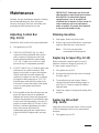
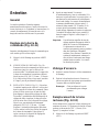
Maintenance
Normally, the only maintenance required is cleaning
the unit and tightening nuts, bolts, and screws.
However, the scraper, drive belt, rotor blades, and
spark plug should be checked once a year.
Adjusting Control Bar
(Fig. 10-11)
Periodically check control bar for proper adjustment.
1. Turn ignition key to OFF.
2. CHECK ADJUSTMENT (Fig. 10)–Move
control bar back toward handle until slack in
cable is removed. Gap between control bar
bracket and handle should be approximately
1/16”–1/8”. If cable is too loose or too tight,
proceed to step 3 for adjustment procedure.
3. ADJUST CABLE (Fig. 11)–Unhook upper cable
end from hole in control bar bracket. Slide
spring cover up cable to expose cable adjuster.
Unhook cable end from cable adjuster and
reposition in a higher or lower hole on adjuster
as required to attain proper gap of 1/16”–1/8”.
Reinstall upper cable end into rear hole (hole
with arrow) in control bar bracket. Slide spring
cover over cable adjuster and recheck
adjustment.
4. After extended use the drive belt may wear and
proper belt tension may not be maintained,
Improper belt tension causes belt slippage and
decreases the snowthrower’s performance under
a heavy load. Belt slippage may occur after 2-3
seasons of normal usage (10-15 hours). If drive
belt slips (continuous squealing noise) under
heavy load, increase belt tension by
repositioning spring end into forward hole in
control bar bracket. Readjust cable (see steps
2-3).
IMPORTANT: Unnecessary use of forward
adjusting hole in control bar bracket reduces
drive belt life. Occasional belt slippage
(squealing) may occur in extremely wet
conditions due to moisture in drive system. To
remove moisture, start rotor and operate
under no load for 30 seconds. Once moisture
is removed, belt should not slip.
Draining Gasoline
1. Stop engine. Remove key from switch.
2. Remove cap from fuel tank and use a pump-type
syphon to drain fuel into a clean gas can.
Note: This is the only procedure
recommended for draining fuel.
Replacing Scraper (Fig. 12-13)
Before each season, inspect scraper for wear. If
thickness of bottom of scraper is less than 1/16”
(1.6 mm), replace scraper (Fig. 11).
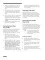
1. Turn ignition key to OFF.
2. Drain gasoline from fuel tank; refer to Draining
Gasoline, page 11.
3. Tip snowthrower up onto its nose. Remove
carriage bolts and locknuts holding scraper in
place (Fig. 13). Remove scraper by sliding to
right and down.
4. Install new scraper to housing with carriage bolts
and nuts.
Replacing Drive Belt
(Fig. 14-15)
Inspect drive belt before each season. If ribs on inside
of belt are damaged or belt is worn, replacement is
necessary.
1. Turn ignition key to OFF.

GB–12
2. Remove (3) self tapping screws, (2) capscrews,
(1) washer and (2) nuts securing belt cover to
snowthrower frame (Fig. 14). Set belt cover
aside.
3. REMOVING BELT (Fig. 15)–Push down on
idler pulley allowing belt to be removed from
rotor pulley, brake arm assembly, and engine
pulley.
4. INSTALLING BELT (Fig. 15)–Loop belt around
engine pulley, under idler pulley, over roller,
through brake assembly, and around rotor pulley.
IMPORTANT: Belt must be on top of roller
as shown.
5. Reinstall belt cover. Tighten fasteners securely,
but DO NOT OVERTIGHTEN.
Replacing Spark Plug
(Fig. 16-18)
Before each snow season, check the spark plug. If
electrodes in center of plug are dark or have
deteriorated, install a new plug. Use an NGK
BPMR4A spark plug and set gap at .032” (.81 mm).
1. REMOVE CONTROL PANEL
(Fig. 16)–Remove (3) capscrews securing
control panel to housing. Remove ignition key
and lift off panel, allowing it to hang on recoil
rope.
2. REMOVE SPARK PLUG (Fig. 17)–Pull wire
off spark plug and remove plug. Examine the
plug and replace if cracked, fouled or dirty. DO
NOT SANDBLAST, SCRAPE OR CLEAN
SPARK PLUG BECAUSE DIRT MAY
RELEASE AND FALL INTO CYLINDER
CAUSING ENGINE DAMAGE.
3. INSTALL SPARK PLUG–Set air gap (Fig. 18)
between electrodes at .032” (.81 mm). Install
plug and tighten to 15 ft–lb (20.4 Nm). If torque
wrench is not used, tighten plug firmly. Push
wire onto spark plug and reinstall control panel
with (3) capscrews.
Adjusting Carburetor
The carburetor has been factory set, and no
adjustment is required. However, when operating
snowthrower at altitudes of 5000 feet above sea level
or higher, carburetor jets may have to be changed.
Contact your local Authorized Toro Service Dealer
for assistance.
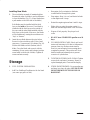
Replacing Rotor Blades
(Fig. 19-20)
Before each snow season, inspect rotor blades for
wear. When blade edge has worn to the wear indicator
hole (Fig. 19), the blades must be replaced to ensure
proper performance and prevent damage to underside
of snowthrower. Always replace both blades at the
same time.
Note: Whenever rotor blades are replaced,
scraper should also be replaced to
ensure proper snowthrower operation
and performance.
Removing Old Blade
1. Remove (4) torx screws and (4) locknuts
securing outer edges of rotor blade to rotor shaft
assembly (Fig. 20).
2. Next, remove (2) hex–head capscrews, spacers
and locknuts securing center of blade to steel
plates (Fig. 20).
3. Loosen the hex-head screw securing the rotor
halves to the auger shaft assembly (Fig. 20).
4. Slide the blade out from between the rotor halves
(Fig. 20).
La page est en cours de chargement...
La page est en cours de chargement...
La page est en cours de chargement...
La page est en cours de chargement...
La page est en cours de chargement...
La page est en cours de chargement...
La page est en cours de chargement...
La page est en cours de chargement...
La page est en cours de chargement...
La page est en cours de chargement...
La page est en cours de chargement...
La page est en cours de chargement...
La page est en cours de chargement...
La page est en cours de chargement...
La page est en cours de chargement...
La page est en cours de chargement...
-
 1
1
-
 2
2
-
 3
3
-
 4
4
-
 5
5
-
 6
6
-
 7
7
-
 8
8
-
 9
9
-
 10
10
-
 11
11
-
 12
12
-
 13
13
-
 14
14
-
 15
15
-
 16
16
-
 17
17
-
 18
18
-
 19
19
-
 20
20
-
 21
21
-
 22
22
-
 23
23
-
 24
24
-
 25
25
-
 26
26
-
 27
27
-
 28
28
-
 29
29
-
 30
30
-
 31
31
-
 32
32
-
 33
33
-
 34
34
-
 35
35
-
 36
36


Toro CCR 2000 Snowthrower Manuel utilisateur
- Catégorie
- Souffleuses à neige
- Taper
- Manuel utilisateur
dans d''autres langues
Documents connexes
-
Toro CCR 1000 Snowthrower Manuel utilisateur
-
-
-
-
Toro 724 Snowthrower Manuel utilisateur
-
-
-
-
-