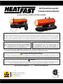
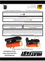
HEATFAST HeatFast Kerosene Forced Air Heater Series Le manuel du propriétaire
- Catégorie
- Cheminées
- Taper
- Le manuel du propriétaire

853556-1802i
®
HF45K / HF75K / HF125K / HF175K / HF215K
A Subsidiary of U.S. Stove Company
227
Industrial Dr., South Pittsburg, TN
PH: (423) 837-5155
www.powerfastproducts.com
READ AND SAVE THESE INSTRUCTIONS
Carefully read and understand these instrucons before assembling, operang, or servicing this heater. You may injure
yourself or others if you do not follow the instrucons. This manual has been designed to instruct you on the proper
manner in which to assemble, maintain, store, and most importantly, how to operate the heater in a safe and ecient
manner. Do not allow anyone who has not read these instrucons to assemble, light, adjust or operate the heater.
U. S. RESIDENTS:
THE INSTALLATION OF THIS HEATER SHALL BE
IN ACCORDANCE WITH THE REGULATION OF
AUTHORITIES HAVING JURISDICTION AND NFPA 31
CANADIAN RESIDENTS:
THIS HEATER SHALL BE OPERATED IN ACCORDANCE
WITH THE REGULATION OF AUTHORITIES HAVING
JURISDICTION AND CSA STANDARD B139.
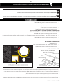
Not for Use in Living Areas • Suitable for Outdoor Use
Oil Fired Forced Air
Construction Heater
CALIFORNIA PROPOSITION 65 WARNING:
This product can expose you to chemicals including carbon monoxide, which is known to the State of California to cause
cancer, birth defects and/or other reproducve harm. For more informaon, go to www.P65warnings.ca.gov
DANGER:
THIS HEATER IS DESIGNED AND INTENDED FOR SPACE-HEATING OF BUILDINGS UNDER CONSTRUCTION AND
FOR SPOT HEATING WHEN THE PRODUCTS OF COMBUSTION ARE DISCHARGED OUTDOORS.

-2-
WARNING: Never leave the heater unattended while operating.
Disconnect the heater from its power source when not in use.
GENERAL HAZARD WARNING
FAILURE TO COMPLY WITH THE PRECAUTIONS AND INSTRUCTIONS PROVIDED WITH THIS HEATER CAN RESULT IN
DEATH, SERIOUS BODILY INJURY AND PROPERTY LOSS OR DAMAGE FROM HAZARDS OF FIRE, EXPLOSION, BURN,
ASPHYXIATION, CARBON MONOXIDE POISONING, AND / OR ELECTRICAL SHOCK.
ONLY PERSONS WHO CAN UNDERSTAND AND FOLLOW THESE INSTRUCTIONS SHOULD USE OR SERVICE THIS
HEATER.
IF YOU NEED ASSISTANCE OR HEATER INFORMATION SUCH AS AN INSTRUCTIONS MANUAL, LABEL, ETC. CONTACT
THE MANUFACTURER.
WARNING:
FIRE, BURN, INHALATION, AND EXPLOSION HAZARD. KEEP SOLID COMBUSTIBLES, SUCH AS BUILDING MATERIALS,
PAPER, OR CARDBOARD, A SAFE DISTANCE AWAY FROM THE HEATER AS RECOMMENDED BY THE INSTRUCTIONS.
NEVER USE THE HEATER IN SPACES WHICH DO OR MAY CONTAIN VOLATILE OR AIRBORNE COMBUSTIBLES, OR
PRODUCTS SUCH AS GASOLINE, SOLVENTS, PAINT THINNER, DUST PARTICLES OR UNKNOWN CHEMICALS.
WARNING: NOT FOR HOME OR RECREATIONAL VEHICLE USE.
WARNING: RISK OF CARBON MONOXIDE POISONING
• Use this heater only in well venlated areas! Provide at
least a three square feet (2,800 sq cm) opening of outside
air for every 45,000 BTU/Hr. of heater rang.
• People with breathing problems should consult a physician
before using the heater.
• Early signs of carbon monoxide poisoning resemble flu-like
symptoms such as headaches, dizziness, and/or nausea. If
you have these symptoms, your heater may not be working
properly.
• Get fresh air at once! Have the heater serviced.
• Some people are more affected by carbon monoxide than
others. These include pregnant women, those with heart
or lung problems, anemia, those under the influence of
alcohol, or at high altudes.
• Never use this heater in living or sleeping areas.
DANGER
WARNING
CAUTION
NOTICE
Residents of New York City, NY:
New York Fire Code prohibits the storage, handling and use
of kerosene fueled heaters for space heang. Any person
violang that provision may be punished by a ne of up to
$10,000 and a term of imprisonment of up to 6 months.
Residents of Massachuses:
Massachuses State Law prohibits the use of this heater
in any building which is used whole or in part for human
habitaon. Use of this device requires local re department
permit (M.G.L.C. 148, Secon 10A)

-3-
WARNING: Never leave the heater unattended while operating.
Disconnect the heater from its power source when not in use.
WARNING:
• DO NOT START HEATER WHEN CHAMBER IS HOT.
• DO NOT START HEATER WHEN EXCESS FUEL HAS
ACCUMULATED IN THE CHAMBER.
• NOT FOR USE WITH AN EXTERNAL FUEL TANK.
• DO NOT USE GASOLINE OR CRANKCASE DRAINING,
NAPHTHA OR VOLATILE FUELS.
• DO NOT FILL THE TANK WHILE THE UNIT IS OPERATING.
• FOR USE ON NON-COMBUSTIBLE FLOORING WITH
MINIMUM CLEARANCES TO COMBUSTIBLE MATERIALS.
• HOT WHILE IN OPERATION. DO NOT TOUCH.
• KEEP CHILDREN, CLOTHING, PETS AND COMBUSTIBLES
AWAY FROM HEATER.
• NEVER POINT THE HEATER TOWARD A PROPANE
CYLINDER.
• KEEP BULK FUEL STORAGE A MINIMUM OF 25 FEET (8
METERS) FROM HEATER.
• STORE FUEL ACCORDING TO FEDERAL, STATE, AND/OR
LOCAL AUTHORITIES.
• ALWAYS FILL THE HEATER OUTDOORS AND KEEP
AWAY FROM OPEN FLAME.
• EQUIPMENT MUST BE GROUNDED.
• NEVER HANDLE HEATER WHILE HOT.
• NEVER TRANSPORT HEATER WITH FUEL IN THE TANK.
• WHEN USED WITH AN OPTIONAL THERMOSTAT OR
IF EQUIPPED WITH A THERMOSTAT, THE HEATER MAY
START AT ANY TIME.
• ALWAYS LOCATE THE HEATER ON A STABLE AND LEVEL
SURFACE.
• ALLOW THE HEATER TO COOL BEFORE HANDLING OR
TRANSPORTING.
• BEFORE MOVING THE HEATER, WAIT UNTIL THE
HEATER HAS COMPLETELY COOLED AND BE CERTAIN
THE FUEL CAP IS SECURELY AND TIGHTLY CLOSED.
WARNING: RISK OF ELECTRIC SHOCK
• EQUIPMENT MUST BE GROUNDED.
• Use only the power (voltage) specied for this heater.
Refer to the model plate on the heater.
• Use only a three-prong grounded outlet and extension
cord.
• ALWAYS install heater so that it is not directly exposed to
water spray, rain, dripping water, or wind.
• ALWAYS disconnect the heater from its power source
when not in use.
WARNING:
Do Not Tamper With The Heater. Have A Competent
Serviceman Make Any Necessary Adjustments Or Repairs.
WARNING:
• NEVER block the air inlet (rear) or air outlet (front)
• NEVER aach duct work in front or in rear of the heater.

-4-
WARNING: Never leave the heater unattended while operating.
Disconnect the heater from its power source when not in use.
WARNING:
•
quarters.
•
CO
2
, And NO
2
•
•
2
•
•
•
•
•
2
, and NO
2
•
•
•
CO 50 ppm
CO
2
5000 ppm
NO
2
N/A
CO N/A
CO
2
N/A
NO
2
5 ppm
CO
CO
2
NO
2
5 ppm
CO 100 ppm
CO
2
15000 ppm (WSBC)
30000 ppm (Reg 833)
NO
2
1.0 ppm (WSBC)
5.0 ppm (Reg 833)

-5-
WARNING: Never leave the heater unattended while operating.
Disconnect the heater from its power source when not in use.
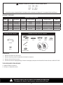
GENERAL SPECIFICATIONS
Model
Type of
Fuel
BTU Rang
Pump
Pressure
Fuel Tank Capacity
Fuel
Consumpon
Electrical Input Fuse
R45K Kerosene 45,000 BTU 3.3 PSI 5.3 Gal 0.32 gal/h 120V, 60Hz /1.2 Amp 250V/10 Amp
R75K Kerosene 75,000 BTU 3.2 PSI 5.3 Gal 0.55 gal/h 120V, 60Hz /1.3 Amp 250V/10 Amp
R125K Kerosene 125,000 BTU 5.2 PSI 10.6 Gal 0.95 gal/h 120V, 60Hz / 2.1 Amp 250V/10 Amp
R175K Kerosene 175,000 BTU 6.0 PSI 13.2 Gal 1.32 gal/h 120V, 60Hz / 2.5 Amp 250V/10 Amp
R215K Kerosene 210,000 BTU 7.0 PSI 13.2 Gal 1.58 gal/h 120V, 60Hz / 2.7 Amp 250V/10 Amp
UNPACKING
1. Remove the heater from the carton.
2. Remove all packing materials applied to the heater for shipment.
3. Remove all items from the carton.
4. Check the heater for shipping damage. If heater is damaged, promptly inform PowerFast Product Group at (423) 837-5155.
TOOLS REQUIRED FOR ASSEMBLY
• Medium Phillips screwdriver
• M5 open, or adjustable wrench
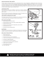
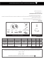
PRODUCT FEATURES
PARTS LIST
WARNING: MINIMUM CLEARANCE FROM COMBUSTIBLES
FONT 10 / 3.0 m
SIDES 3 / 1.0 m
TOP 3 /1.0 m
FOR USE ON NON-COMBUSTIBLE FLOORING WITH MINIMUM CLEARANCES TO COMBUSTIBLE MATERIALS.
Handle
Ø5x1
Axle
M6
M6x1 M8x1 Cap Nut
T2.0xØ13xØ2 Wheels
Shaft fixed Bkt
MODELS: R125K / R175K / R215K
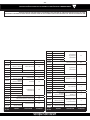
GENERAL SPECIFICATIONS
Model
Type of
Fuel
BTU Rang
Pump
Pressure
Fuel Tank Capacity
Fuel
Consumpon
Electrical Input Fuse
HF45K Kerosene 45,000 BTU 3.3 PSI 5.3 Gal 0.32 gal/h 120V, 60Hz /1.2 Amp 250V/10 Amp
HF75K Kerosene 75,000 BTU 3.2 PSI 5.3 Gal 0.55 gal/h 120V, 60Hz /1.3 Amp 250V/10 Amp
HF125K Kerosene 125,000 BTU 5.2 PSI 10.6 Gal 0.95 gal/h 120V, 60Hz / 2.1 Amp 250V/10 Amp
HF175K Kerosene 175,000 BTU 6.0 PSI 13.2 Gal 1.32 gal/h 120V, 60Hz / 2.5 Amp 250V/10 Amp
HF215K Kerosene 210,000 BTU 7.0 PSI 13.2 Gal 1.58 gal/h 120V, 60Hz / 2.7 Amp 250V/10 Amp
Handle
Ø5x1
Axle
M6
M6x1 M8x1 Cap Nut
T2.0xØ13xØ2 Wheels
Shaft fixed Bkt
MODELS: HF125K / HF175K / HF215K

-6-
WARNING: Never leave the heater unattended while operating.
Disconnect the heater from its power source when not in use.
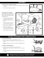
TO ATTACH THE GUARD
1. Remove the screws from the upper shell and set aside.
2. Align the holes in the Guard with the holes in the upper shell as
shown.
3. Secure the guard to the upper shell by inserng and ghtening the
screws.
TO ATTACH THE INTERCEPTOR
1. Remove the screws from the lower shell and set aside.
2. Align the holes in the Interceptor with the holes in the lower shell
as shown.
3. Secure the Interceptor to the lower shell by inserng and ghtening
the screws.
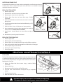
ASSEMBLY
1. Align the holes in the upper housing with the two mounng holes on the handle
as shown.
2. Secure handle through holes provided.
Screw
Handle
Interception
Guard
Interception
Guard
Handle
Air
Inlet
Fuel
Tank
Flange
Axle
Wheel
Wheel
Support
Frame
Thermostat
Knob
Handle Installaon R45K / R75K
Models R125K / R175K / R215K
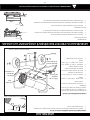
FOR MODELS WITH WHEELS
These models come complete with
wheels and handles. Wheels, handles
and mounng hardware are located in
the shipping carton.
1. Loosely secure the Axle Bracket
to the Wheel Support Frame.
2. Slide the axle through the Axle
Bracket.
3. Install the wheels on the axle,
with the valve facing outward.
4. Place the flat washers and
fastening nut on the axle ends.
5. Tighten the Axle Brackets.
6. Posion the Height Adjustment
Pipe to align the hole as shown.
7. Insert and ghten the bolt (M8).
Handle Installaon HF45K / HF75K
Models HF125K / HF175K / HF215K

-7-
WARNING: Never leave the heater unattended while operating.
Disconnect the heater from its power source when not in use.
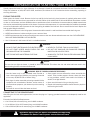
PREPARATION FOR STARTING YOUR HEATER
Visually inspect the heater for signs of damage. If any damage is found do not operate the heater. Contact PowerFast Product
Group for assistance at (423) 837-5155. Read, understand, and follow all of the instrucons before assembling, operang or
servicing this heater.
FUELING THE HEATER
Make certain the heater is level. Remove the fuel cap and ll the fuel tank with clean kerosene for opmal performance of this
heater. This heater has been factory approved for use with JP8/Jet A, #1 and #2 Fuel Oil, #1 and #2 Diesel. Diesel does not burn
as clean as 1-K kerosene, and care should be taken to provide more fresh air venlaon to accommodate any added contaminants
that may be produced during operaon of the heater. In extreme cold temperatures, it is recommended a fuel stabilizer formulated
to remove condensaon and to prevent the fuel from gelling be added to the fuel tank. Do not overll the fuel tank. Replace the
fuel cap aer lling the fuel tank.
• NEVER store kerosene in the living space. Kerosene should be stored in a well venlated area outside the living area.
• NEVER store kerosene in direct sunlight or near a source of heat.
• NEVER use kerosene that has been stored from one season to the next. Kerosene deteriorates over me. OLD KEROSENE
WILL NOT BURN PROPERLY IN THIS HEATER.
• Use 1-K kerosene in this heater. #1 fuel is a suitable substute.
WARNING:
• DO NOT START HEATER WHEN THE HEATER IS HOT.
• DO NOT START HEATER WHEN EXCESS FUEL HAS
ACCUMULATED IN THE CHAMBER.
• NOT FOR USE WITH AN EXTERNAL FUEL TANK.
• NEVER FILL THE FUEL TANK IN LIVING SPACE
• DO NOT USE GASOLINE OR CRANKCASE DRAINING,
NAPHTHA OR VOLATILE FUELS.
• ALWAYS FILL THE FUEL TANK OUTDOORS AWAY FROM
LIVING AREAS.
NOTICE:
The rst me you light the heater, it should be done OUTDOORS. This allows the oils, and other lubricants used in the
manufacturing process to be burned off outside.
WARNING: RISK OF CARBON MONOXIDE POISONING
• Use this heater only in well venlated areas! Provide at
least a three square feet (2,800 sq cm) opening of outside
air for every 45,000 BTU/Hr. of heater rang.
• Early signs of carbon monoxide poisoning resemble flu-like
symptoms such as headaches, dizziness, and/or nausea. If
you have these symptoms, your heater may not be working
properly.
• Get fresh air at once! Have the heater serviced.
• Some people are more affected by carbon monoxide than
others. These include pregnant women, those with heart
or lung problems, anemia, those under the influence of
alcohol, or at high altudes.
• Never use this heater in living or sleeping areas.
• People with breathing problems should consult a physician
before using the heater.
CONNECTING TO THE POWER SOURCE
Aer lling the fuel tank with approved fuel, connect the plug to a 3-prong, grounded extension cord adequately rated for this
applicaon.
Extension Cord Wire Size Requirements:
• 6 to 10 feet (1.8 to 3 meters) long, use 18 AWG conductor.
• 11 to 100 feet (3.4 to 30.53 meters) long, use 16 AWG conductor.
• 101 to 200 feet (30.8 to 61 meters) long, use 14 AWG conductor.

-8-
WARNING: Never leave the heater unattended while operating.
Disconnect the heater from its power source when not in use.
°F
Temperature /
Température (°F)
112°F /
44°C
45°F /
7°C
Continue /
Continuer
Starting Procedures / Procédures
de démarrage
1.Fill tank with 1-K Kerosene /
Remplissez le réservoir de
carburant de kérosène 1-K.
2.Plug into 120V/60Hz power /
Branchez sur une alimentation
120V/60Hz
3.Set thermostat to desired
temperature / Réglez le thermostat
à la température souhaitée
4.Push Power Switch to “ON” /
Basculez l'interrupteur principal
sur la position « ON » (MARCHE).
Shut-Down Procedures /
Procédures d'arrêt
1.Push Power Switch to “OFF” /
Basculez l'interrupteur princ
ipal
sur la position « OFF » (ARRÊT).
2.Allow to cool / Laissez le radiateur
refroidir
3.Unplug from power source /
Débranchez-le de la source
d'alimentation
The room temperature display will indicate the following:
* When the temperature is less than 0° F, the display says “LO”
* When the temperature is more than 99° F, the display says “HI”
* Between 0° F and 99° F the display shows the actual room temperature
Power
Reset
Switch
Lamp
Thermostat
Control Knob
Room Temp.Display
MAINTENANCE
SHUTTING DOWN THE HEATER
1. Push the Power Buon to the "OFF" posion.
2. Wait for heater to cool, then unplug the heater from
its power source.
RESTARTING THE HEATER
1. Wait 10 seconds aer powering down the heater.
2. Push the Power Switch to the "ON" posion.
3. If heater does not start, the thermostat seng may be lower than the ambient temperature. Turn the Thermostat Control
Knob to a higher temperature seng. If the heater sll does not start, turn the Power Switch "OFF". Wait 10 seconds. Turn
the Power Switch "ON"
RESTARTING THE HEATER AFTER SAFETY SHUTDOWN
1. Push the Power Buon to the "OFF" posion.
2. Unplug the heater from its power source.
3. Wait 10 seconds for the system to reset.
4. Plug the heater into its power source.
5. Push the Power Buon to the "ON" posion.
WARNING: DO NOT TAMPER WITH THE HEATER. HAVE A COMPETENT SERVICEMAN MAKE ANY NECESSARY
ADJUSTMENTS OR REPAIRS.
WARNING: DISCONNECT THE HEATER FROM ITS POWER SOURCE BEFORE SERVICING.
WARNING: HOT WHILE IN OPERATION. DO NOT TOUCH. ALLOW HEATER TO COOL BEFORE SERVICING.
ADJUSTING THE THERMOSTAT
• Turn the Thermostat Control Knob clockwise to the desired heat seng. Push the Power Switch to the “ON” posion. The
Power Indicator Lamp will light and the heater will start.
• If heater does not start, the thermostat seng may be lower than the ambient temperature.
• Turn the Thermostat Control Knob to a higher temperature seng.
• If the heater sll does not start, turn the Power Switch “OFF”. Wait 10 seconds. Turn the Power Switch “ON”. NOTE: The
major electrical components of this heater are protected by a safety fuse mounted to the PCB board located behind the Right
Side Panel. If your heater fails to start, check this fuse rst and replace as necessary. You should also check your power source
to insure that proper voltage and frequency are being supplied to the heater.
Controls for Models R75K / R125K / R175K / R215K
Controls for Models HF75K / HF125K / HF175K / HF215K

-9-
WARNING: Never leave the heater unattended while operating.
Disconnect the heater from its power source when not in use.
BEFORE OPERATING THIS HEATER
Visually inspect for damage. Some parts may have become loose or were damaged from handling. Be certain the fuel cap is
securely fastened and check that the drain plug (if applicable for your model) is installed properly. Replace or repair any damaged
parts before operang this heater. USE ORIGINAL EQUIPMENT REPLACEMENT PARTS. Use of third party or other alternate
components will void the warranty and may cause unsafe operang condions. If you need replacement parts or require assistance,
contact PowerFast Product Group at (423) 837-5155.
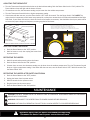
AIR INTAKE FILTER
Dirty Intake Filters can cause an imbalance in the fuel-to-air mixture, resulng in
rough starng, poor combuson and odors. Never operate a heater without the
lters in place.
Remove and wash the intake with a mild detergent and water. Thoroughly dry and
replace the lter. Clean the lters every 500 hours as needed.
AIR OUTPUT FILTER AND LINT FILTER
The Output and the Lint Filter are not designed to be cleaned and reused. Do not
wash these lters. Replace dirty lters at the start of each season.
REPLACING AIR FILTERS
1. Remove Upper Shell and Fan Guard.
2. Remove End Filter Cover screws using a medium Phillips screwdriver.
3. Remove End Filter Cover.
4. Replace the Air Intake Filter, Air Output Filter, and Lint Filter.
5. Reinstall End Filter Cover.
6. Reinstall Fan Guard and Upper Shell.
PHOTOCELL
The opcal lens can become dirty or clouded in use. Clean the lens using isopropyl
alcohol or water and a so cloth or coon swab every 500 hours or as needed.
REPLACING THE PHOTOCELL
1. Remove Upper Shell.
2. Remove Right Side Panel.
3. Disconnect wires from circuit board (PCB).
4. Twist to loosen Photocell from the Photocell Bracket.
5. Clean lens or replace Photocell.
6. Insert Photocell into Photocell Bracket.
7. Properly align the Photocell within the Bracket.
8. Aach wires to circuit board.
9. Reinstall Right Side Panel.
10. Secure Upper Shell.
Lint Filter
Air Out Put Filter
Intake Filter
End Filter Cover
Improper Alignment Proper Alignment

-10-
WARNING: Never leave the heater unattended while operating.
Disconnect the heater from its power source when not in use.
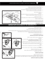
NOZZLE AND SPARK PLUG
Contaminated fuel, build-up of carbon, and accumulated dirt can affect the performance
of these parts. Clean or replace these parts every 500 hours or as needed to ensure
opmal performance of the heater.
REPLACING THE NOZZLE
1. Remove Upper Shell.
2. Disconnect Air and Fuel Lines from the Nozzle Rod.
3. Remove ignitor wires from the Spark Plug.
4. Remove Spark Plug from the Nozzle Rod using a Phillips
screwdriver.
5. Twist the Nozzle Rod counterclockwise to remove it from the
Burner Head.
6. Carefully remove the Nozzle from the Nozzle Rod using a 5/8”
socket wrench.
7. Soak the nozzle in clean 1-K Kerosene to loosen parcles.
8. Inject compressed air into the front opening of the nozzle to
loosen parculate. WEAR SAFETY GLASSES.
9. Install new (or cleaned) Nozzle into Nozzle Rod and ghten
rmly.
10. Reassemble by reversing steps listed above.
REPLACING THE SPARK PLUG
1. Remove Upper Shell.
2. Remove igniter wire from Spark Plug.
3. Remove Spark Plug from Nozzle Rod using medium Phillip screwdriver.
4. Clean and re-gap the Spark Plug electrodes to 0.140 inches (3.5 mm) gap.
5. Reinstall Spark Plug into Nozzle Rod.
6. Aach igniter wires to Spark Plug.
7. Secure Upper Shell.
Nozzle
Rod
Nozzle Face
Nozzle Rod
Nozzle
Nozzle
Rod
Spark Plug
Fuel Hose
Fitting
Air Hose Fitting
Gap
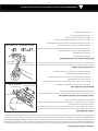
FUEL FILTER
The Fuel Filter should be cleaned or replaced at the start of the season and
as needed throughout the season to ensure opmal performance by the
heater. Clean the Fuel Filter by rinsing the screen with clean 1-K Kerosene.
Replacing the Fuel Filter
1. Remove the Right Side Panel screws using a medium Phillips
screwdriver.
2. Remove Side Cover.
3. Disconnect the Fuel Line from the Fuel Filter neck.
4. Turn Fuel Filter counterclockwise 90 degrees using an adjustable
wrench.
5. Pull upwards and remove.
6. Wash Fuel Filter with clean 1-K Kerosene.
Side Cover
Power Switch
Power Switch Wire
Screw
Fuel Filter
Fuel Line
SEASONAL MAINTENANCE SCHEDULE

-11-
WARNING: Never leave the heater unattended while operating.
Disconnect the heater from its power source when not in use.
MODEL R45K R75K R125K R175K R215K
PUMP
PRESSURE
3.3 PSI 3.2 PSI 5.2 PSI 6.0 PSI 7.0 PSI
7. Insert Fuel Filter in the Fuel Tank and using adjustable wrench turn the Filter 90 degrees clockwise.
8. Aach Fuel Line to Fuel Filter neck.
9. Reinstall side cover with screws provided.
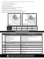
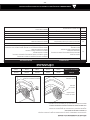
ADJUSTING PUMP PRESSURE
Aer hours of use it may be necessary to adjust the Pump Pressure.
Increase the pressure by turning the adjustment screw clockwise.
Reduce the pressure by turning the adjustment screw counterclockwise.
TROUBLESHOOTING
POSSIBLE CAUSE CORRECTIVE ACTION
E1
Photocell (Flame Color Checking Sensor) Error
Oil Shortage
Bad Photocell (Flame Sensor)
Incomplete Combuson
Contaminaon of Fuel Filter
Ignion Failure
Charge Fuel (Fill the fuel if needed)
Check and clean or replace Photocell (Flame Sensor)
Using Designated Fuel
Clean or replace Fuel Filter
Check Wire Connecon
Check Spark Plug For Normal Firing (clean or replace if needed)
E2
Temperature Sensor (Thermister) Error
Bad Connecon or Sensor Error
Check Wire Connecon
Replace Sensor
LO Below 1°F Normal
HI Over 99°F Normal
OH
Heater stops when the temperature reaches to
140°F
Restart Aer Cooling
CN
Connuously operang without set-
temperature
Normal
Blinking Error during operaon
Check Error Code
Reset to Restart
Pressure
Gauge
Plug
Relief
Valve
Adjusng Pump Pressure
Model R75K
Adjusng Pump Pressure
Model R125K, R175K, R215K
MODEL HF45K HF75K HF125K HF175K HF215K
PUMP
PRESSURE
3.3 PSI 3.2 PSI 5.2 PSI 6.0 PSI 7.0 PSI
Pressure
Gauge
Plug
Relief
Valve
Adjusng Pump Pressure
Model HF75K
Adjusng Pump Pressure
Model HF125K, HF175K, HF215K

-12-
WARNING: Never leave the heater unattended while operating.
Disconnect the heater from its power source when not in use.
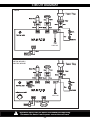
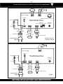
CIRCUIT DIAGRAM
Power Plug
PF75K / PF125K /
PF175K / PF215K
250V/10A
Power Plug
250V/10A
R75K / R125K /
R175K / R215K
HF75K / HF125K /
HF175K / HF215K

-13-
WARNING: Never leave the heater unattended while operating.
Disconnect the heater from its power source when not in use.
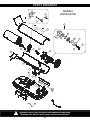
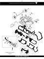
PARTS DIAGRAM
22
20
18
5
6
7
8
16
17
21
11
12
13
15
14
24
9
10
2
4
3
19
23
MODELS
MODELS

-14-
WARNING: Never leave the heater unattended while operating.
Disconnect the heater from its power source when not in use.
9
10
20
22
2
4
3
17
18
5
6
7
8
16
11
12
15
24
19
23
13
14
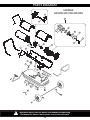
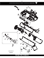
PARTS DIAGRAM
MODELS
R125K/R175K/R215K
MODELS
HF125K/HF175K/HF215K

-15-
WARNING: Never leave the heater unattended while operating.
Disconnect the heater from its power source when not in use.
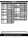
PARTS LIST
KEY DESCRIPTION MODEL PART NO
1 Drain Plug
R125K, R175K,
R215K
893090
2
Fuel Gauge
Assembly
R45K, R75K 892822
R125K, R175K,
R215K
892823
3
Fuel Filter
Assembly
R45K, R75K 892824
R125K, R175K,
R215K
892825
4 Fuel Cap Assembly 892826
5 Air Line
R45K, R75K 892813
R125K, R215K 892814
R175K 892815
6 Thermostat Limit Control 80719
7 Fuel Line
R45K, R75K 893091
R125K, R215K 893092
R175K 893093
8 Photocell 80819
9 Nozzle Assembly
R45K 893094
R75K 892827
R125K 892828
R175K 892829
R215K 892830
10 Spark Plug 80729
11
Motor & Pump
Assembly
R45K 80821
R75K 80742
R125K 80743
R175K 80744
R215K 80745
In order to maintain warranty, components must be replaced using original manufacturer’s parts purchased
through your dealer or directly from PowerFast Product Group at (423) 837-5155. Use of third party
components will void the warranty.
KEY DESCRIPTION MODEL PART NO
12 Rotor Kit
R45K, R75K,
R125K, R175K
893075
R215K 893076
13 Air Filter Kit 892831
14 End Filter Cover 892816
15 Pump Adjustment Kit 83759
16 Fan Assembly
R45K 893082
R75K 893083
R125K 893084
R175K 893085
R215K 893086
17 Igniter
R45K, R75K 80727
R125K, R175K,
R215K
80726
18 Thermistor
R75K, R125K,
R175K, R215K
80275
19 PCB 80728
20 Clips 83790
21 Top Handle R45K, R75K 892819
22 Heat Shield
R45K, R75K 893077
R125K, R175K,
R215K
893074
23 Fuse 250V/10A 80818
24 Pressure Gauge 81322
KEY DESCRIPTION MODEL PART NO
1 Drain Plug
HF125K, HF175K,
HF215K
893090
2
Fuel Gauge
Assembly
HF45K, HF75K 892822
HF125K, HF175K,
HF215K
892823
3
Fuel Filter
Assembly
HF45K, HF75K 892824
HF125K, HF175K,
HF215K
892825
4 Fuel Cap Assembly 892826
5 Air Line
HF45K, HF75K 892813
HF125K, HF215K 892814
HF175K 892815
6 Thermostat Limit Control 80719
7 Fuel Line
HF45K, HF75K 893091
HF125K, HF215K 893092
HF175K 893093
8 Photocell 80819
9 Nozzle Assembly
HF45K 893094
HF75K 892827
HF125K 892828
HF175K 892829
HF215K 892830
10 Spark Plug 80729
11
Motor & Pump
Assembly
HF45K 80821
HF75K 80742
HF125K 80743
HF175K 80744
HF215K 80745
KEY DESCRIPTION MODEL PART NO
12 Rotor Kit
HF45K, HF75K,
HF125K, HF175K
893075
HF215K 893076
13 Air Filter Kit 892831
14 End Filter Cover 892816
15 Pump Adjustment Kit 83759
16 Fan Assembly
HF45K 893082
HF75K 893083
HF125K 893084
HF175K 893085
HF215K 893086
17 Igniter
HF45K, HF75K 80727
HF125K, HF175K,
HF215K
80726
18 Thermistor
HF75K, HF125K,
HF175K, HF215K
80275
19 PCB 80728
20 Clips 83790
21 Top Handle HF45K, HF75K 892819
22 Heat Shield
HF45K, HF75K 893077
HF125K, HF175K,
HF215K
893074
23 Fuse 250V/10A 80818
24 Pressure Gauge 81322

853392
PowerFast warrants this product, to the original retail purchaser only, to be free from defects in material and workmanship
for a period of one (1) year from the date of the initial purchase as evidenced on an invoice, canceled check, sales receipt,
etc. In the event of a defect, this Limited Warranty shall be limited to the repair or replacement of parts, which prove
defective under normal use and service within the limited warranty period, and which PowerFast deems at its reasonable
discretion. THE LIMITED WARRANTY SET FORTH HEREIN IS THE SOLE WARRANTY PROVIDED TO PURCHASER AND
IS IN LIEU OF ALL OTHER WARRANTIES AND REPRESENTATIONS, EXPRESS OR IMPLIED. POWERFAST MAKES NO
REPRESENTATIONS OR WARRANTIES WHATSOEVER, EXPRESS OR IMPLIED, WITH RESPECT TO THE PRODUCT,
OTHER THAN (i) THE LIMITED WARRANTY ABOVE, AND (ii) ANY IMPLIED WARRANTIES IMPOSED BY APPLICABLE
LAW WHICH CANNOT BE WAIVED OR DISCLAIMED UNDER APPLICABLE LAW. ALL OTHER WARRANTIES OF ANY
KIND, INCLUDING WITHOUT LIMITATION IMPLIED WARRANTIES OF MERCHANTABILITY AND FITNESS FOR A
PARTICULAR PURPOSE, ARE HEREBY DISCLAIMED AND EXCLUDED TO THE FULLEST EXTENT NOT PROHIBITED
BY APPLICABLE LAW. This Limited Warranty gives the purchaser specific legal rights; a purchaser may have other rights
depending upon where he or she resides. Some states do not allow the exclusion or limitation of special, incidental or
consequential damages, or state law may aect the duration of limitations, so the above exclusion and limitations may
not be applicable.
OTHER LIMITATIONS: PowerFast disclaims all other warranties for products that are purchased from sellers other than
authorized retailers or distributors. This product must be properly installed, maintained and operated in accordance
with the instructions provided herein. Furthermore, PowerFast requires reasonable proof of the date of purchase from
an authorized retailer or distributor. This Limited Warranty does not cover any operational failures or diculties due
to normal use and wear and tear, accident, abuse, misuse, alteration, misapplication, improper installation or improper
maintenance or service by you or any third party. Failure to perform normal and routine maintenance on the product,
shipping damage related to animals, and damage due to weather are not covered under this Limited Warranty. In addition,
this Limited Warranty does not cover damage to the finish on the product, such as scratches, dents, discoloration, rust
or other weather damage. This warranty does not apply to products purchased for rental use. PowerFast assumes no
responsibility for any defects caused by third parties. PowerFast does not authorize any person or company to assume
for it any other obligation or liability in connection with the sale, installation, use, removal, return, or replacement of its
products, and no such representations are binding on PowerFast.
CLAIM PROCEDURE: All transportation costs for the return of the damaged product or parts will be the responsibility
of the purchaser. Upon receipt of the product, PowerFast will examine it and determine if the product contains a defect.
PowerFast will repair or replace and return the item, freight pr-paid. If PowerFast finds the item to be in normal operating
condition, or not defective, the item will be returned freight collect. Purchaser shall specify the model number(s) and
serial number(s) of any product(s) when making any claims with PowerFast. Please use the following to identify your
product:
Model #: ________________________________________
Serial #: ________________________________________
LIMITED WARRANTY
PRODUCT GROUP

L’entreprise PowerFast garantit ce produit, seulement à l’acheteur commercial original, d’être sans défaut matériel ou
manutentionnaire pour une période d’un (1) an, à partir de la date d’achat initiale, tel que convenu sur la facture, sur
le chèque annulé sur le reçu de l’achat, etc. En cas de défaut, cette garantie limitée est limitée à la réparation ou au
remplacement des pièces qui se prouvées défectueuses selon l’usage normal et le service normal, convenu à l’intérieur
de la garantie limitée, et qui est jugé convenable à la discrétion de PowerFast. LA GARANTIE LIMITÉE DÉNOTÉE
CI-JOINT EST LA SEULE GARANTIE FOURNIE À L’ACHETEUR ET EST EN LIEU DE TOUT AUTRE GARANTIE OU
REPRÉSENTATION, EXPRESSE OU IMPLICITE. POWERFAST NE FAIT AUCUNE REPRÉSENTATION OU GARANTIE QUE
CE SOIT, QU’ELLE SOIT IMPLICITE OU EXPRESSE, EN RESPECT AU PRODUIT, AUTRE QUE (i) LA GARANTIE LIMITÉE
MENTIONNÉE CI-DESSUS, ET (ii) TOUTE GARANTIE IMPLICITE IMPOSÉE PAR LA LOI APPLICATION QUI NE PEUT
ÊTRE ANNULÉE OU DÉCLINÉES SELON LA LOI APPLICABLE. TOUTE AUTRE GARANTIE, DE TOUT GENRE, INCLUANT
MAIS SANS S’Y LIMITER AUX GARANTIES IMPLICITES DE QUALITÉ MARCHANDE OU D’APTITUDE POUR UN BUT
PARTICULIER, SONT DONC DÉCLINÉES ET EXCLUSES AU PLUS HAUT POINT SELON LA LOI APPLICABLE. Cette
garantie limitée donne à l’acheteur des droits légaux spécifiques; un acheteur pourrait avoir des droits diérents selon
son lieu de résidence. Certains états ne permettent pas l’exclusion ou la limitation de dommages spécifiques, accessoires
ou consécutifs, ou des lois d’état qui peuvent aecter la durée des limitations; l’exclusion et les limitations précédentes
pourraient ne pas s’appliquer.
AUTRES LIMITATIONS: PowerFast décline toutes autres garanties pour les produits qui sont achetés auprès d’autres
vendeurs que ceux autorisés. Ce produit doit être proprement installé, entretenu et doit fonctionner selon les instructions
ci-jointes. De plus, PowerFast requiert une preuve raisonnable de la date d’achat eectuée auprès du fournisseur ou
du distributeur autorisé. Cette garantie limitée ne couvre pas les échecs ou les dicultés opérationnelles dus à un
usage régulier et à l’usure, aux accidents, aux abus, à l’abus, aux altérations, à l’installation ou à l’entretien incorrects
eectués par vous ou par une troisième partie. Un échec d’eectuer l’entretien normal et routinier de ce produit, les
dommages d’expédition, les dommages eectués par des animaux, et ceux faits par les événements météorologiques
ne sont pas couverts dans cette garantie limitée. Également, cette garantie limitée ne couvre pas le dommage fait au fini
de ce produit, comme les égratignures, les bosses, la discoloration du produit, la rouille ou tout autres dommages faits
par les événements météorologiques. Cette garantie ne s’applique pas aux produits achetés pour la location. PowerFast
n’assume aucune responsabilité envers les défauts eectués par des troisièmes parties. PowerFast n’autorise aucune
personne ou aucune entreprise d’assumer pour ellemême toute obligation ou toute forme de responsabilité pour la vente,
l’installation, l’utilisateur, l’enlèvement, le retour ou le remplacement de ses produits, et aucune de ces représentations ne
permette de lier PowerFast.
PROCÉDURE DE RÉCLAMATION: Tous les coûts de transport pour le retour d’un produit ou de pièces endommagés
seront de la responsabilité de l’acheteur. Au moment de la réception du produit, PowerFast examinera et déterminera si
le produit est défectueux ou non. PowerFast réparera ou remplacement et retournera le produit, par transport prépayé. Si
PowerFast trouve que le produit fonctionne selon les normes de fonctionnement normales, et qu’il n’est pas défectueux,
le produit sera retourné par port dû. Les acheteurs devront spécifier le numéro du mpdèle et le numéro de série de tout
produit lorsqu’ils feront les réclamations auprès d’PowerFast. Veuillez fournir les informations suivantes afin d’identifier
votre produit:
Modèle #: _______________________________________
No de série: _____________________________________
GARANTIE LIMITÉE
PRODUCT GROUP

-15-
AVERTISSEMENT : Ne laissez jamais ce radiateur sans surveillance lorsqu'il fonctionne.
Toujours débrancher ce radiateur lorsque vous ne l'utilisez pas.
LISTE DES PIÈCES
RÉFÉRENCE DESCRIPTION MODÈLE NO. DE PIÈCE
1 Bouchon de vidange
R125K, R175K,
R215K
893090
2
Assemblage de la
jauge de carburant
R45K, R75K 892822
R125K, R175K,
R215K
892823
3
Assemblage du ltre
à carburant
R45K, R75K 892824
R125K, R175K,
R215K
892825
4 Assemblage du bouchon du réservoir 892826
5 Conduite d’air
R45K, R75K 892813
R125K, R215K 892814
R175K 892815
6 Contrôle de la limite du thermostat 80719
7 Ligne de carburant
R45K, R75K 893091
R125K, R215K 893092
R175K 893093
8 Cellule photoélectrique 80819
9
Assemblage
de l'embout
R45K 893094
R75K 892827
R125K 892828
R175K 892829
R215K 892830
10 Bougie d’allumage 80729
11
Assemblage
du moteur et
de la pompe
R45K 80821
R75K 80742
R125K 80743
R175K 80744
R215K 80745
RÉFÉRENCE DESCRIPTION MODÈLE NO. DE PIÈCE
12 Trousse du rotor
R45K, R75K,
R125K, R175K
893075
R215K 893076
13 Trousse du ltre à air 892831
14 Couverture de l'extrémité du ltre 892816
15 Trousse de réglage de la pompe 83759
16
Assemblage
du venlateur
R45K 893082
R75K 893083
R125K 893084
R175K 893085
R215K 893086
17 Allumeur
R45K, R75K 80727
R125K, R175K,
R215K
80726
18 Thermistance
R75K, R125K,
R175K, R215K
80275
19 PCB 80728
20 Pinces 83790
21 Poignée supérieure R45K, R75K 892819
22 Écran thermique
R45K, R75K 893077
R125K, R175K,
R215K
893074
23 Disjoncteur 250 V/ 10 A 80818
24 Manomètre 81322
RÉFÉRENCE DESCRIPTION MODÈLE
NO. DE
PIÈCE
1 Bouchon de vidange
HF125K, HF175K,
HF215K
893090
2
Assemblage de la
jauge de carburant
HF45K, HF75K 892822
HF125K, HF175K,
HF215K
892823
3
Assemblage du ltre
à carburant
HF45K, HF75K 892824
HF125K, HF175K,
HF215K
892825
4 Assemblage du bouchon du réservoir 892826
5 Conduite d’air
HF45K, HF75K 892813
HF125K, HF215K 892814
HF175K 892815
6 Contrôle de la limite du thermostat 80719
7 Ligne de carburant
HF45K, HF75K 893091
HF125K, HF215K 893092
HF175K 893093
8 Cellule photoélectrique 80819
9
Assemblage
de l'embout
HF45K 893094
HF75K 892827
HF125K 892828
HF175K 892829
HF215K 892830
10 Bougie d’allumage 80729
11
Assemblage
du moteur et
de la pompe
HF45K 80821
HF75K 80742
HF125K 80743
HF175K 80744
HF215K 80745
RÉFÉRENCE DESCRIPTION MODÈLE
NO. DE
PIÈCE
12 Trousse du rotor
HF45K, HF75K,
HF125K, HF175K
893075
HF215K 893076
13 Trousse du ltre à air 892831
14 Couverture de l'extrémité du ltre 892816
15 Trousse de réglage de la pompe 83759
16
Assemblage
du venlateur
HF45K 893082
HF75K 893083
HF125K 893084
HF175K 893085
HF215K 893086
17 Allumeur
HF45K, HF75K 80727
HF125K, HF175K,
HF215K
80726
18 Thermistance
HF75K, HF125K,
HF175K, HF215K
80275
19 PCB 80728
20 Pinces 83790
21 Poignée supérieure HF45K, HF75K 892819
22 Écran thermique
HF45K, HF75K 893077
HF125K, HF175K,
HF215K
893074
23 Disjoncteur 250 V/ 10 A 80818
24 Manomètre 81322

-15-
AVERTISSEMENT : Ne laissez jamais ce radiateur sans surveillance lorsqu'il fonctionne.
Toujours débrancher ce radiateur lorsque vous ne l'utilisez pas.
LISTE DES PIÈCES
RÉFÉRENCE DESCRIPTION MODÈLE NO. DE PIÈCE
1 Bouchon de vidange
R125K, R175K,
R215K
893090
2
Assemblage de la
jauge de carburant
R45K, R75K 892822
R125K, R175K,
R215K
892823
3
Assemblage du ltre
à carburant
R45K, R75K 892824
R125K, R175K,
R215K
892825
4 Assemblage du bouchon du réservoir 892826
5 Conduite d’air
R45K, R75K 892813
R125K, R215K 892814
R175K 892815
6 Contrôle de la limite du thermostat 80719
7 Ligne de carburant
R45K, R75K 893091
R125K, R215K 893092
R175K 893093
8 Cellule photoélectrique 80819
9
Assemblage
de l'embout
R45K 893094
R75K 892827
R125K 892828
R175K 892829
R215K 892830
10 Bougie d’allumage 80729
11
Assemblage
du moteur et
de la pompe
R45K 80821
R75K 80742
R125K 80743
R175K 80744
R215K 80745
RÉFÉRENCE DESCRIPTION MODÈLE NO. DE PIÈCE
12 Trousse du rotor
R45K, R75K,
R125K, R175K
893075
R215K 893076
13 Trousse du ltre à air 892831
14 Couverture de l'extrémité du ltre 892816
15 Trousse de réglage de la pompe 83759
16
Assemblage
du venlateur
R45K 893082
R75K 893083
R125K 893084
R175K 893085
R215K 893086
17 Allumeur
R45K, R75K 80727
R125K, R175K,
R215K
80726
18 Thermistance
R75K, R125K,
R175K, R215K
80275
19 PCB 80728
20 Pinces 83790
21 Poignée supérieure R45K, R75K 892819
22 Écran thermique
R45K, R75K 893077
R125K, R175K,
R215K
893074
23 Disjoncteur 250 V/ 10 A 80818
24 Manomètre 81322
-14-
AVERTISSEMENT : Ne laissez jamais ce radiateur sans surveillance lorsqu'il fonctionne.
Toujours débrancher ce radiateur lorsque vous ne l'utilisez pas.
9
10
20
22
2
4
3
17
18
5
6
7
8
16
11
12
15
24
19
23
13
14
SCHÉMA DES PIÈCES
MODÈLES
R125K/R175K/R215K
MODÈLES
HF125K/HF175K/HF215K

-13-
AVERTISSEMENT : Ne laissez jamais ce radiateur sans surveillance lorsqu'il fonctionne.
Toujours débrancher ce radiateur lorsque vous ne l'utilisez pas.
22
20
18
5
6
7
8
16
17
21
11
12
13
15
14
24
9
10
2
4
3
19
23
SCHÉMA DES PIÈCES
MODÈLES
MODÈLES
La page est en cours de chargement...
La page est en cours de chargement...
La page est en cours de chargement...
La page est en cours de chargement...
La page est en cours de chargement...
La page est en cours de chargement...
La page est en cours de chargement...
La page est en cours de chargement...
La page est en cours de chargement...
La page est en cours de chargement...
La page est en cours de chargement...
La page est en cours de chargement...
-
 1
1
-
 2
2
-
 3
3
-
 4
4
-
 5
5
-
 6
6
-
 7
7
-
 8
8
-
 9
9
-
 10
10
-
 11
11
-
 12
12
-
 13
13
-
 14
14
-
 15
15
-
 16
16
-
 17
17
-
 18
18
-
 19
19
-
 20
20
-
 21
21
-
 22
22
-
 23
23
-
 24
24
-
 25
25
-
 26
26
-
 27
27
-
 28
28
-
 29
29
-
 30
30
-
 31
31
-
 32
32


HEATFAST HeatFast Kerosene Forced Air Heater Series Le manuel du propriétaire
- Catégorie
- Cheminées
- Taper
- Le manuel du propriétaire
dans d''autres langues
Documents connexes


Autres documents
-
United States Stove Ranger Kerosene Forced Air Heater Series Le manuel du propriétaire
-
 Thermoheat RMC-KFA210TL User's Manual And Operating Instructions
-
 Mi-T-M MH-0400-0M10 Kerosene Portable Heater Le manuel du propriétaire
-
Mi-T-M MH-0125-0M10 Manuel utilisateur
-
 Mi-T-M MH-0600-0M10 Kerosene Portable Heater Le manuel du propriétaire
-
Dura Heat DuraHeat DFA-170C Manuel utilisateur
-
 Mi-T-M MH-0400-0M10 Manuel utilisateur
-
 Mi-T-M Kerosene Portable Heater Le manuel du propriétaire
-
Dyna-Glo RMC-KFA75TDGD Manuel utilisateur
-


