RIDGID 7 1/4" Wormdrive Saw Manuel utilisateur
- Catégorie
- Coupeuses universelles de puissance
- Taper
- Manuel utilisateur
Ce manuel convient également à

OPERATOR’S MANUAL
MANUEL D’UTILISATION
MANUAL DEL OPERADOR
7-1/4 in. WORM DRIVE SAW
184 mm SCIE À TRANSMISSION À VIS
184 mm SIERRA CON ENGRANAJE SINFÍN
R32104
TABLE OF CONTENTS
****************
General Power Tool Safety
Warnings .........................................2-3
Circular Saw Safety Warnings .........3-4
Symbols ..............................................5
Electrical ............................................. 6
Features ..............................................7
Assembly .........................................7-8
Operation .......................................8-12
Adjustments .....................................12
Maintenance ................................13-14
Accessories ......................................14
Illustrations ..................................15-17
Parts Ordering and
Service ................................Back page
TABLE DES MATIÈRES
****************
Avertissements de sécurité relatives
aux outils electriques ......................2-3
Avertissements de sécurité relatifs scie
circulaire ..........................................3-4
Symboles ............................................5
Caractéristiques électriques ...............6
Caractéristiques .................................7
Assemblage .....................................7-8
Utilisation .......................................8-12
Réglages ...........................................12
Entretien ......................................13-14
Accessoires ......................................14
Illustrations ..................................15-17
Commande de pièces et
dépannage ........................Page arrière
ÍNDICE DE CONTENIDO
****************
Advertencias de seguridad para
herramientas eléctricas .................. 2-3
Advertencias de seguridad sierra
circular ............................................3-4
Símbolos ............................................5
Aspectos eléctricos ............................6
Características ...................................7
Armado ........................................... 7-8
Funcionamiento ............................ 8-12
Ajustes ..............................................12
Mantenimiento ............................ 13-14
Accesorios ........................................14
Ilustraciones ............................... 15-17
Pedidos de piezas y
servicio ..........................Pág. posterior
Includes: Circular saw, blade, hex key,
Operator’s Manual
Inclut : Scie circulaire, lame, clé
hexagonale, manuel d’utilisation
Incluye: Sierra circular, hoja, llave
hexagonal, manual del operador
SAVE THIS MANUAL
FOR FUTURE REFERENCE
CONSERVER CE MANUEL
POUR FUTURE RÉFÉRENCE
GUARDE ESTE MANUAL
PARA FUTURAS CONSULTAS
WARNING:
To reduce the risk of injury, the
user must read and understand
the operator’s manual before
using this product.
AVERTISSEMENT :
Pour réduire les risques de
blessures, l’utilisateur doit lire
et veiller à bien comprendre
le manuel d’utilisation avant
d’utiliser ce produit.
ADVERTENCIA:
Para reducir el riesgo de
lesiones, el usuario debe leer
y comprender el manual del
operador antes de usar este
producto.
To register your RIDGID product,
please visit:
http://register.RIDGID.com
Pour enregistrer votre produit de
RIDGID, s’il vous plaît la visite :
http://register.RIDGID.com
Para registrar su producto
de RIDGID, por favor visita:
http://register.RIDGID.com

2 - English
WARNING
Read all safety warnings and all instructions.
Failure to follow the warnings and instructions may
result in electric shock, fire and/or serious injury.
Save all warnings and instructions for future reference.
The term “power tool” in the warnings refers to your mains-
operated (corded) power tool or battery-operated (cordless)
power tool.
WORK AREA SAFETY
Keep work area clean and well lit. Cluttered or dark
areas invite accidents.
Do not operate power tools in explosive atmo-
spheres, such as in the presence of flammable
liquids, gases, or dust. Power tools create sparks which
may ignite the dust or fumes.
Keep children and bystanders away while operating a
power tool. Distractions can cause you to lose control.
ELECTRICAL SAFETY
Power tool plugs must match the outlet. Never modify
the plug in any way. Do not use any adapter plugs with
earthed (grounded) power tools. Unmodified plugs and
matching outlets will reduce risk of electric shock.
Avoid body contact with earthed or grounded surfaces
such as pipes, radiators, ranges and refrigerators.
There is an increased risk of electric shock if your body
is earthed or grounded.
Do not expose power tools to rain or wet conditions.
Water entering a power tool will increase the risk of elec-
tric shock.
Do not abuse the cord. Never use the cord for carry-
ing, pulling or unplugging the power tool. Keep cord
away from heat, oil, sharp edges, or moving parts.
Damaged or entangled cords increase the risk of electric
shock.
When operating a power tool outdoors, use an exten-
sion cord suitable for outdoor use. Use of a cord suit-
able for outdoor use reduces the risk of electric shock.
If operating a power tool in a damp location is unavoid-
able, use a ground fault circuit interrupter (GFCI) pro-
tected supply. Use of a GFCI reduces the risk of electric
shock.
PERSONAL SAFETY
Stay alert, watch what you are doing and use
common sense when operating a power tool. Do
not use a power tool while you are tired or under the
influence of drugs, alcohol or medication. A moment
of inattention while operating power tools may result in
serious personal injury.
Use personal protective equipment. Always wear eye
protection. Protective equipment such as dust mask,
non-skid safety shoes, hard hat, or hearing protection
used for appropriate conditions will reduce personal
injuries.
Prevent unintentional starting. Ensure the switch is in
the off-position before connecting to power source
and/or battery pack, picking up or carrying tool.
Carrying power tools with your finger on the switch or
energising power tools that have the switch on invites
accidents.
Remove any adjusting key or wrench before turning
the power tool on. A wrench or a key left attached to
a rotating part of the power tool may result in personal
injury.
Do not overreach. Keep proper footing and balance
at all times. This enables better control of the power tool
in unexpected situations.
Dress properly. Do not wear loose clothing or jewel-
lery. Keep your hair, clothing, and gloves away from
moving parts. Loose clothes, jewellery or long hair can
be caught in moving parts.
If devices are provided for the connection of dust
extraction and collection facilities, ensure these are
connected and properly used. Use of dust collection
can reduce dust-related hazards.
POWER TOOL USE AND CARE
Do not force the power tool. Use the correct power tool
for your application.
The correct power tool will do the
job better and safer at the rate for which it was designed.
Do not use the power tool if the switch does not turn
it on and off. Any power tool that cannot be controlled
with the switch is dangerous and must be repaired.
Disconnect the plug from the power source and/or
the battery pack from the power tool before making
any adjustments, changing accessories, or storing
power tools. Such preventive safety measures reduce
the risk of starting the power tool accidentally.
Store idle power tools out of the reach of children and
do not allow persons unfamiliar with the power tool
or these instructions to operate the power tool. Power
tools are dangerous in the hands of untrained users.
Maintain power tools. Check for misalignment or bind-
ing of moving parts, breakage of parts, and any other
condition that may affect the power tool’s operation.
If damaged, have the power tool repaired before use.
Many accidents are caused by poorly maintained power
tools.
Keep cutting tools sharp and clean. Properly main-
tained cutting tools with sharp cutting edges are less
likely to bind and are easier to control.
GENERAL POWER TOOL SAFETY WARNINGS

3 - English
DANGER:
Keep hands away from cutting area and the
blade. Keep your second hand on auxiliary
handle, or motor housing. If both hands are
holding the saw, they cannot be cut by the blade.
Do not reach underneath the workpiece. The guard
can not protect you from the blade below the workpiece.
Adjust the cutting depth to the thickness of the
workpiece. Less than a full tooth of the blade teeth
should be visible below the workpiece.
Never hold piece being cut in your hands or across
your leg. Secure the workpiece to a stable platform.
It is important to support the work properly to minimize
body exposure, blade binding, or loss of control.
Hold the power tool by insulated gripping surfaces only,
when performing an operation where the cutting tool
may contact hidden wiring or its own cord.
Contact with
a “live” wire will also make exposed metal parts of the
power tool “live” and could give the operator an electric
shock.
When ripping, always use a rip fence or straight edge
guide. This improves the accuracy of cut and reduces
the chance of blade binding.
Always use blades with correct size and shape
(diamond versus round) of arbour holes. Blades that
do not match the mounting hardware of the saw will run
eccentrically, causing loss of control.
Never use damaged or incorrect blade washers or
bolt. The blade washers and bolt were specially designed
for your saw, for optimum performance and safety of
operation.
KICKBACK CAUSES AND RELATED WARNINGS
Kickback is a sudden reaction to a pinched, bound or
misaligned saw blade, causing an uncontrolled saw to
lift up and out of the workpiece toward the operator;
When the blade is pinched or bound tightly by the kerf
closing down, the blade stalls and the motor reaction
drives the unit rapidly back toward the operator;
If the blade becomes twisted or misaligned in the cut,
the teeth at the back edge of the blade can dig into the
top surface of the wood causing the blade to climb out
of the kerf and jump back toward the operator.
Kickback is the result of saw misuse and/or incorrect
operating procedures or conditions and can be avoided by
taking proper precautions as given below:
Maintain a firm grip with both hands on the saw and
position your arms to resist kickback forces. Position
your body to either side of the blade, but not in line
with the blade. Kickback could cause the saw to jump
backwards, but kickback forces can be controlled by the
operator, if proper precautions are taken.
When blade is binding, or when interrupting a cut
for any reason, release the trigger and hold the saw
motionless in the material until the blade comes to a
complete stop. Never attempt to remove the saw from
the work or pull the saw backward while the blade is
in motion or kickback may occur. Investigate and take
corrective actions to eliminate the cause of blade binding.
When restarting a saw in the workpiece, centre the
saw blade in the kerf and check that saw teeth are
not engaged into the material. If saw blade is binding,
it may walk up or kickback from the workpiece as the
saw is restarted.
Support large panels to minimise the risk of blade
pinching and kickback. Large panels tend to sag under
their own weight. Supports must be placed under the
panel on both sides, near the line of cut and near the
edge of the panel.
Do not use dull or damaged blades. Unsharpened
or improperly set blades produce narrow kerf causing
excessive friction, blade binding and kickback.
Blade depth and bevel adjusting locking levers must be
tight and secure before making cut. If blade adjustment
shifts while cutting, it may cause binding and kickback.
Use extra caution when sawing into existing walls or
other blind areas. The protruding blade may cut objects
that can cause kickback.
Use the power tool, accessories and tool bits etc.
in accordance with these instructions, taking into
account the working conditions and the work to be
performed. Use of the power tool for operations different
from those intended could result in a hazardous situation.
SERVICE
Have your power tool serviced by a qualified repair
person using only identical replacement parts. This will
ensure that the safety of the power tool is maintained.
GENERAL POWER TOOL SAFETY WARNINGS
CIRCULAR SAW SAFETY WARNINGS
CUTTING PROCEDURES

4 - English
LOWER GUARD FUNCTION
Check lower guard for proper closing before each
use. Do not operate the saw if lower guard does not
move freely and close instantly. Never clamp or tie the
lower guard into the open position. If saw is accidentally
dropped, lower guard may be bent. Raise the lower guard
with the retracting handle and make sure it moves freely
and does not touch the blade or any other part, in all
angles and depths of cut.
Check the operation of the lower guard spring. If the
guard and the spring are not operating properly, they
must be serviced before use. Lower guard may operate
sluggishly due to damaged parts, gummy deposits, or a
build-up of debris.
Lower guard should be retracted manually only for
special cuts such as “plunge cuts” and “compound
cuts.” Raise lower guard by retracting handle and as
soon as blade enters the material, the lower guard
must be released. For all other sawing, the lower guard
should operate automatically.
Always observe that the lower guard is covering the
blade before placing saw down on bench or floor. An
unprotected, coasting blade will cause the saw to walk
backwards, cutting whatever is in its path. Be aware of the
time it takes for the blade to stop after switch is released.
ADDITIONAL SAFETY WARNINGS
Use clamps or other practical way to secure and
support the workpiece to a stable platform. Holding the
work by hand or against your body is unstable and may
lead to loss of control.
Know your power tool. Read operator’s manual
carefully. Learn its applications and limitations, as well
as the specific potential hazards related to this tool.
Following this rule will reduce the risk of electric shock,
fire, or serious injury.
Always wear eye protection with side shields marked
to comply with ANSI Z87.1. Failure to do so could
result in objects being thrown into your eyes, resulting in
possible serious injury.
Protect your lungs. Wear a face or dust mask if the
operation is dusty. Following this rule will reduce the
risk of serious personal injury.
Protect your hearing. Wear hearing protection during
extended periods of operation. Following this rule will
reduce the risk of serious personal injury.
Inspect tool cords periodically and, if damaged, have
repaired at your nearest authorized service center.
Constantly stay aware of cord location. Following this
rule will reduce the risk of electric shock or fire.
Check damaged parts. Before further use of the
tool, a guard or other part that is damaged should
be carefully checked to determine that it will operate
properly and perform its intended function. Check for
alignment of moving parts, binding of moving parts,
breakage of parts, mounting, and any other conditions
that may affect its operation. A guard or other part that
is damaged should be properly repaired or replaced
by an authorized service center. Following this rule will
reduce the risk of shock, fire, or serious injury.
Make sure your extension cord is in good condition.
When using an extension cord, be sure to use one
heavy enough to carry the current your product
will draw. A wire gauge size (A.W.G.) of at least
12 is recommended for an extension cord 50 feet
or less in length. A cord exceeding 100 feet is not
recommended. If in doubt, use the next heavier gauge.
The smaller the gauge number, the heavier the cord.
An undersized cord will cause a drop in line voltage
resulting in loss of power and overheating.
Inspect for and remove all nails from lumber before
using this tool. Following this rule will reduce the risk of
serious personal injury.
If the power supply cord is damaged, it must be
replaced only by the manufacturer or by an authorized
service center to avoid risk.
Save these instructions. Refer to them frequently and
use them to instruct others who may use this tool. If you
loan someone this tool, loan them these instructions also.
CALIFORNIA PROPOSITION 65
WARNING:
This product and some dust created by power sanding, sawing, grinding, drilling, and other construction activities
may contain chemicals, including lead, known to the State of California to cause cancer, birth defects, or other
reproductive harm. Wash hands after handling.
Some examples of these chemicals are:
• lead from lead-based paints,
• crystalline silica from bricks and cement and other masonry products and,
• arsenic and chromium from chemically treated lumber.
Your risk from exposure to these chemicals varies, depending on how often you do this type of work. To reduce
your exposure, work in a well-ventilated area and with approved safety equipment, such as dust masks that are
specially designed to filter out microscopic particles.
CIRCULAR SAW SAFETY WARNINGS

5 - English
SYMBOLS
Some of the following symbols may be used on this product. Please study them and learn their meaning. Proper
interpretation of these symbols will allow you to operate the product better and safer.
Safety Alert Indicates a potential personal injury hazard.
Read Operator’s Manual
To reduce the risk of injury, user must read and understand
operator’s manual before using this product.
Eye Protection
Always wear eye protection with side shields marked to comply
with ANSI Z87.1.
Wet Conditions Alert Do not expose to rain or use in damp locations.
No Hands Symbol
Failure to keep your hands away from the blade will result in serious
personal injury.
Alternating Current Type of current
n
o
No Load Speed Rotational speed, at no load
.../min Per Minute Revolutions, strokes, surface speed, orbits etc., per minute
V Volts Voltage
A Amperes Current
Hz Hertz Frequency (cycles per second)
min Minutes Time
SYMBOL NAME
DESIGNATION/EXPLANATION
The following signal words and meanings are intended to explain the levels of risk associated with this product.
SYMBOL SIGNAL MEANING
DANGER:
Indicates an imminently hazardous situation, which, if not avoided, will result
in death or serious injury.
WARNING:
Indicates a potentially hazardous situation, which, if not avoided, could result
in death or serious injury.
CAUTION:
Indicates a potentially hazardous situation, which, if not avoided, may result in
minor or moderate injury.
NOTICE:
(Without Safety Alert Symbol) Indicates important information not related to an
injury hazard, such as a situation that may result in property damage.

6 - English
ELECTRICAL
EXTENSION CORDS
Use only 3-wire extension cords that have 3-prong grounding
plugs and 3-pole receptacles that accept the tool's plug.
When using a power tool at a considerable distance from
the power source, use an extension cord heavy enough
to carry the current that the tool will draw. An undersized
extension cord will cause a drop in line voltage, resulting in
a loss of power and causing the motor to overheat. Use the
chart provided below to determine the minimum wire size
required in an extension cord. Only round jacketed cords
listed by Underwriter's Laboratories (UL) should be used.
**Ampere rating (on tool faceplate)
0-2.0 2.1-3.4 3.5-5.0 5.1-7.0 7.1-12.0 12.1-16.0
Cord Length Wire Size (A.W.G.)
25' 16 16 16 16 14 14
50' 16 16 16 14 14 12
100' 16 16 14 12 10 —
**Used on 12 gauge - 20 amp circuit.
NOTE: AWG = American Wire Gauge
When working with the tool outdoors, use an extension cord
that is designed for outside use. This is indicated by the
letters “W-A” or “W” on the cord’s jacket.
Before using an extension cord, inspect it for loose or
exposed wires and cut or worn insulation.
WARNING:
Keep the extension cord clear of the working
area. Position the cord so that it will not get
caught on lumber, tools or other obstructions
while you are working with a power tool. Failure
to do so can result in serious personal injury.
WARNING:
Check extension cords before each use. If
damaged replace immediately. Never use
product with a damaged cord since touching
the damaged area could cause electrical shock
resulting in serious injury.
ELECTRICAL CONNECTION
This product is powered by a precision built electric motor.
It should be connected to a power supply that is 120 V, AC
only (normal household current), 60 Hz. Do not operate
this product on direct current (DC). A substantial voltage
drop will cause a loss of power and the motor will overheat.
If the saw does not operate when plugged into an outlet,
double check the power supply.
SPEED AND WIRING
The no-load speed of this tool is approximately 5,000 rpm.
This speed is not constant and decreases under a load or
with lower voltage. For voltage, the wiring in a shop is as
important as the motor’s horsepower rating. A line intended
only for lights cannot properly carry a power tool motor. Wire
that is heavy enough for a short distance will be too light for
a greater distance. A line that can support one power tool
may not be able to support two or three tools.
GROUNDING INSTRUCTIONS
This product must be grounded. In the event of a malfunction
or breakdown, grounding provides a path of least resistance
for electric current to reduce the risk of electric shock. This
tool is equipped with an electric cord having an equipment-
grounding conductor and a grounding plug. The plug must be
plugged into a matching outlet that is properly installed and
grounded in accordance with all local codes and ordinances.
Do not modify the plug provided. If it will not fit the outlet,
have the proper outlet installed by a qualified electrician.
WARNING:
Improper connection of the grounding plug can
result in a risk of electric shock. When repair
or replacement of the cord is required, do not
connect the grounding wire to either flat blade
terminal. The wire with insulation having an
outer surface that is green with or without yellow
stripes is the grounding wire.
Check with a qualified electrician or service personnel if the
grounding instructions are not completely understood, or if
in doubt as to whether the tool is properly grounded.
Repair or replace a damaged or worn cord immediately.
This product is for use on a nominal 120 volt circuit and has
a grounding plug similar to the plug illustrated in figure 1.
Only connect the product to an outlet having the same
configuration as the plug. Do not use an adapter with this
product.
Fig. 1
GROUNDING
PIN
120 V GROUNDED
OUTLET

7 - English
FEATURES
SPECIFICATIONS
Blade Diameter ....................................... 7-1/4 in. (184 mm)
Blade Arbor ...............................Diamond (Bolt-LH Combo)
Cutting Depth at 0° ................................................. 2-3/8 in.
Cutting Depth at 45° ............................................... 1-3/4 in.
Cutting Depth at 56° ........................................... 1-19/64 in.
Input ...........................120 Volts, AC only, 60 Hz, 15 Amps
No Load Speed ........................................5,000/min. (RPM)
UNPACKING
This product requires assembly.
Carefully remove the tool and any accessories from the
box. All items listed in the Includes section must be in-
cluded at the time of purchase.
WARNING:
Items in this Assembly section are not assembled
to the product by the manufacturer and require
customer installation. Use of a product that may
have been improperly assembled could result in
serious personal injury.
Inspect the tool carefully to make sure no breakage or
damage occurred during shipping.
Do not discard the packing material until you have care-
fully inspected and satisfactorily operated the tool.
If any parts are damaged or missing, please call
1-866-539-1710 for assistance.
WARNING:
If any parts are damaged or missing do not operate
this product until the parts are replaced. Use of this
product with damaged or missing parts could result
in serious personal injury.
WARNING:
Do not attempt to modify this tool or create
accessories not recommended for use with this
tool. Any such alteration or modification is misuse
and could result in a hazardous condition leading
to possible serious personal injury.
ASSEMBLY
WARNING:
Do not connect to power supply until assembly
is complete. Failure to comply could result in
accidental starting and possible serious personal
injury.
WARNING:
7-1/4 in. (184 mm) blade is the maximum blade
capacity of the saw. Never use a blade that is too
thick to allow outer flange washer to engage with
the flat on the spindle. Larger blades will come in
contact with the blade guards, while thicker blades
will prevent blade screw from securing blade on
spindle. Either of these situations could result in a
serious accident.
INSTALLING/REMOVING THE BLADE
See Figures 2 - 4, page 15.
To install the blade:
Unplug the saw.
NOTICE:
To prevent damage to the spindle or spindle lock,
always allow the motor to come to a complete stop
before engaging spindle lock.
Depress the spindle lock.
Remove the blade screw by turning it clockwise with the
wrench, while keeping the lock button depressed.
Remove the spring washer and outer flange washer.
Wipe a drop of oil onto the inner flange bushing and outer
flange washer where they contact the blade.
WARNING:
If inner flange bushing has been removed, replace
it before placing the blade on the spindle. Failure
to do so could cause an accident since the blade
will not tighten properly.

8 - English
ASSEMBLY
Retract the lower guard into the upper guard, making
sure the lower guard spring works properly, allowing the
guard to move freely.
Check to see that the saw teeth and arrow on the saw
blade and the arrow on the lower guard are pointing in
the same direction.
NOTE: The saw teeth point upward at the front of the
saw as shown.
Fit the saw blade inside the lower blade guard and onto
the spindle.
NOTE: Be sure that the diamond key on the inner flange
bushing engages properly with the blade before tighten-
ing the blade screw.
Replace outer flange washer.
Replace spring washer.
OPERATION
WARNING:
Do not allow familiarity with the tool to make you
careless. Remember that a careless fraction of a
second is sufficient to inflict severe injury.
WARNING:
Always wear eye protection with side shields
marked to comply with ANSI Z87.1. Failure to do
so could result in objects being thrown into your
eyes, resulting in possible serious injury.
WARNING:
The tool should never be connected to a power
supply when you are assembling parts, making
adjustments, cleaning, performing maintenance, or
when the tool is not in use. Disconnecting the tool
will prevent accidental starting that could cause
serious injury.
APPLICATIONS
You may use this tool for the purposes listed below:
Cutting all types of wood products (lumber, plywood,
paneling)
Depress the spindle lock and replace the blade screw.
Tighten the blade screw securely by turning it counter-
clockwise with the wrench. Do not over tighten.
NOTE: Never use a blade that is too thick to allow
the outer flange washer to engage with the flat on the
spindle.
To remove the blade:
Unplug the saw.
Depress the spindle lock.
Remove blade screw by turning it clockwise with the hex
wrench.
Remove spring washer.
Remove outer flange washer.
Lift lower blade guard.
Remove blade.
WARNING:
Never use abrasive cut-off wheels of any kind
with this saw. Use of non-wood cutting blades
can result in property damage or serious personal
injury.
WARNING:
The use of this saw on materials not listed may
damage the saw and its guards, and may cause
serious personal injury.
SAW BLADES
The best of saw blades will not cut efficiently if they are not
kept clean, sharp, and properly set. Using a dull blade will
place a heavy load on the saw and increase the danger of
kickback. Keep extra blades on hand, so that sharp blades
are always available.
Gum and wood pitch hardened on blades will slow the saw
down. Remove saw blade from the saw and use gum and
pitch remover, hot water, or kerosene to remove these ac-
cumulations. DO NOT USE GASOLINE.

9 - English
OPERATION
BLADE GUARD SYSTEM
See Figure 5, page 15.
The lower blade guard attached to your saw is there for
your protection and safety. Do not alter it for any reason.
If it becomes damaged, do not operate the saw until you
have the guard repaired or replaced. Always leave guard in
operating position when using the saw.
DANGER:
When sawing through work, lower blade guard
does not cover blade on the underside of work.
Since blade is exposed on underside of work, keep
hands and fingers away from cutting area. Any part
of your body coming in contact with moving blade
will result in serious injury.
WARNING:
To avoid possible serious injury, never use saw
when guard is not operating correctly. Check the
guard for correct operation before each use. The
guard is operating correctly when it moves freely,
and instantly returns to the closed position. If you
drop the saw, check the lower blade guard and
bumper for damage at all depth settings before
reuse.
If at any time the lower blade guard does not snap closed,
unplug the saw from the power supply. Exercise the lower
guard by moving it rapidly back and forth from the full open
position to the closed position several times. Normally this
will restore the guard to its normal operating condition. If
it does not correct a slow or sluggish closing lower guard,
do not use the saw. Take it to an authorized factory service
center for repair.
KICKBACK
See Figures 6 - 9, page 16.
Kickback occurs when the blade stalls rapidly and the saw
is driven back towards you. Blade stalling is caused by any
action which pinches the blade in the wood.
WARNING:
Release switch immediately if blade binds or saw
stalls. Kickback could cause you to lose control of
the saw. Loss of control can lead to serious injury.
To guard against kickback, avoid dangerous practices such
as the following.
Setting blade depth incorrectly.
Sawing into knots or nails in workpiece.
Twisting the blade while making a cut.
Making a cut with a dull, gummed up, or improperly set
blade.
Supporting the workpiece incorrectly.
Forcing a cut.
Cutting warped or wet lumber.
Operating the tool incorrectly or misusing the tool.
To lessen the chance of kickback, follow these safety
practices.
Do not cut warped or wet lumber.
Keep the blade at the correct depth setting. The depth set-
ting should not exceed 1/4 in. below the material being cut.
Inspect the workpiece for knots or nails before cutting.
Never saw into a knot or nail.
Make straight cuts. Always use a straight edge guide
when rip cutting. This helps prevent twisting the blade.
Use clean, sharp, and properly set blades. Never make
cuts with dull blades.
Support the workpiece properly before beginning a cut.
Use steady, even pressure when making a cut. Never
force a cut.
Hold the saw firmly with both hands and keep your body
in a balanced position so as to resist the forces if kickback
should occur.
WARNING:
When using the saw, always stay alert and exercise
control. Do not remove the saw from the workpiece
while the blade is moving.
SETTING BLADE DEPTH
See Figure 10, page 16.
Always keep correct blade depth setting. The correct blade
depth setting for all cuts should not exceed 1/4 in. below the
material being cut. More blade depth will increase the chance
of kickback and cause the cut to be rough. For more depth
of cut accuracy, a scale is located on the elevation bracket.
NOTE: The marks on the scale refer to the actual depth of
cut (blade exposure).
Unplug the saw.
Pull depth lock lever upward to release. The depth lock
lever is located between the guard and handle of the saw.
Determine the desired depth of cut.
To select the depth of cut, hold base flat against the
workpiece. Raise or lower saw to align the desired mea-
surement on the scale with the depth arrow indicator,
located directly above the lock mechanism.
Push down on the depth lock lever to lock the lever in
place and secure the position.

10 - English
OPERATION
LENGTH OF CUT SCALE
See Figure 11, page 16.
The length of cut scale on the saw base is parallel with the
saw blade and is used to measure the distance which the
blade cuts into the material.
NOTE: Nine inches is the maximum length of cut that you
can measure. Also, it is accurate only when the depth of cut
is set at full maximum depth.
STARTING/STOPPING THE SAW
See Figure 12, page 16.
To start the saw: Depress the switch trigger.
Always let the blade reach full speed, then guide the saw
into the workpiece.
WARNING:
The blade coming in contact with the workpiece
before it reaches full speed could cause the saw to
“kickback” towards you resulting in serious injury.
To stop the saw: Release the switch trigger.
After you release the switch trigger, allow the blade to
come to a complete stop. Do not remove the saw from the
workpiece while the blade is moving.
OPERATING THE SAW
See Figures 13 - 15, page 16.
It is important to understand the correct method for operat-
ing the saw. Refer to the figures in this section to learn the
correct and incorrect ways for handling the saw.
DANGER:
When lifting the saw from the workpiece, the blade
is exposed on the underside of the saw until the
lower blade guard closes. Make sure the lower
blade guard is closed before setting the saw down.
WARNING:
To make sawing easier and safer, always maintain
proper control of the saw. Loss of control could
cause an accident resulting in possible serious
injury.
To make the best possible cut, follow these helpful hints.
Hold the saw firmly with both hands.
Avoid placing your hand on the workpiece while making
a cut.
Support the workpiece so that the cut is always on your
right.
Support the workpiece near the cut.
Clamp the workpiece securely so that the workpiece will
not move during the cut.
Avoid placing the saw on the part of the workpiece that
will fall off when the cut is made.
Place the workpiece with the “good” side down.
Draw a guideline along the desired line of cut before
beginning the cut.
Keep the cord away from the cutting area. Always place
the cord to prevent it from hanging up on the workpiece
while making a cut.
WARNING:
If the cord hangs up on the workpiece during a cut,
release the switch trigger immediately and allow
the blade to stop. Unplug the saw and reposition
the cord to prevent it from hanging up again.
WARNING:
Using a saw with a damaged cord could result
in serious injury or death. If the cord has been
damaged, have it replaced before using the saw
again.
CROSS CUTTING
When making a cross cut or rip cut, align your line of cut
with the 0° notch on the saw base.
Since blade thicknesses vary, always make a trial cut in scrap
material along a guideline to determine if, and how much,
you must offset the guideline to produce an accurate cut.
NOTE: The distance from the line of cut to the guideline is
the amount you should offset the guide.
RIP CUTTING
See Figures 16 - 17, pages 16 - 17.
Use a guide when making long or wide rip cuts with the saw.
To rip cut using optional edge guide (sold separately):
Secure the workpiece.
Position the face of the edge guide firmly against the
edge of the workpiece.
Guide the saw along the edge to achieve a straight rip
cut.
NOTE: The guiding edge of the workpiece must be straight
for the cut to be straight. Use caution to prevent the blade
from binding in the cut.

11 - English
OPERATION
To rip cut using a straight edge:
Secure the workpiece.
Clamp a straight edge to the workpiece using
C-clamps.
Saw along the straight edge to achieve a straight rip cut.
NOTE: Do not bind the blade in the cut.
BEVEL CUTTING
The base of the saw may be adjusted for bevel cuts up to 56°.
CHECKING/ADJUSTING THE 0° BEVEL STOP
See Figures 18 - 20, page 17.
The positive 0° bevel stop has been factory adjusted to
ensure 0° angle of the saw blade when making 0° cuts.
To check the positive 0° bevel stop:
Unplug the saw.
Place the saw in an upside down position on a workbench.
Move the lower blade guard out of the way so that the
saw blade is exposed.
Check the squareness of the saw blade to the base of
the saw using a combination square.
If adjustment is needed:
Pull the bevel lock lever upward to release.
Using a 2.5 mm hex wrench (not provided) turn the set
screw and adjust the base until it is square with the saw
blade.
Securely lock the bevel lock lever.
SETTING THE BEVEL ANGLE
See Figure 19, page 17.
Unplug the saw.
Pull the bevel lock lever upward until the motor housing
moves freely.
Rotate the motor housing to the desired angle setting on
the bevel scale (0-56°).
Press downward on the bevel lock lever until the motor
housing is securely locked in place.
MAKING A BEVEL CUT
See Figure 21, page 17.
To make the best possible cut:
Align the line of cut with the inner blade guide notch on
the base when making 45° bevel cuts.
Make a trial cut in scrap material along a guideline to
determine how much you should offset the guideline on
the cutting material.
Adjust the angle of cut to any desired setting between
zero and 56°. Positive stops are located at 0°, 15°, 22.5°,
30°, 45° and 56°. Refer to Setting the Bevel Angle earlier
in this manual.
WARNING:
Attempting a bevel cut without having the bevel
lock lever securely locked in place can result in
serious injury.
Hold the saw firmly with both hands as shown.
Rest the front edge of the base on the workpiece.
Start the saw and let the blade reach full speed.
Guide the saw into the workpiece and make the cut.
Release the trigger and allow the blade to come to a
complete stop.
Lift the saw from the workpiece.

12 - English
OPERATION
ADJUSTMENTS
ADJUSTING THE DEPTH LOCK LEVER
See Figure 23, page 17.
Over time, due to wear, the depth lock lever may move from
its original setting. If the lever prematurely contacts any part
of the saw during tightening and loosening, adjust the lever
by following these steps:
Unplug the saw.
Pull depth lock lever upward to release.
Pull saw base down to the minimum depth of cut position,
then push the depth lock lever down to secure.
Insert a flathead screwdriver into the space between the
lock nut and the E-ring. Remove the E-ring.
Note the position of the lever on the nut. Slide the depth
lock lever off the lock nut.
The lock nut has six flat sides. Rotate the depth lock lever
one “flat” counter clockwise around the nut. Then slide it
back into place.
Push the E-ring back into the groove on the lock nut until
it snaps into place. Take care that the E-ring does not
pop off the lock nut.
Loosen the depth lock lever and return the base to the
full depth of cut position and lock the depth setting by
pushing downward on the depth lock lever. The base
should be locked securely in position when locked and
be free to move when released.
ADJUSTING THE BEVEL LOCK LEVER
See Figure 23, page 17.
The bevel lock lever may be adjusted by following the same
steps listed in Adjusting the Depth Lock Lever.
POCKET CUTTING
See Figure 22, page 17.
WARNING:
Always adjust bevel setting to zero before making
a pocket cut. Attempting a pocket cut at any other
setting can result in loss of control of the saw
possibly causing serious injury.
Adjust the bevel setting to zero.
Set the blade to the correct blade depth setting, depend-
ing on the material to be cut.
Swing the lower blade guard up using the lower blade
guard handle.
NOTE: Always raise the lower blade guard with the handle
to avoid serious injury.
Hold the lower blade guard by the handle while keeping
your hand on the front handle as shown.
Rest the front of the base flat against the workpiece with
the rear of the handle raised so the blade does not touch
the workpiece.
Start the saw and let the blade reach full speed.
Guide the saw into the workpiece and make the cut.
WARNING:
Always cut in a forward direction when pocket
cutting. Cutting in the reverse direction could
cause the saw to climb up on the workpiece and
back toward you.
Release the trigger and allow the blade to come to a
complete stop.
Lift the saw from the workpiece.
Clear corners out with a hand saw or sabre saw.
WARNING:
Never tie the lower blade guard in a raised position.
Leaving the blade exposed could lead to serious
injury.

13 - English
MAINTENANCE
WARNING:
When servicing use only identical replacement
parts. Use of any other parts may create a hazard
or cause product damage.
WARNING:
Always wear eye protection with side shields
marked to comply with ANSI Z87.1. Failure to do
so could result in objects being thrown into your
eyes, resulting in possible serious injury.
Do not abuse power tools. Abusive practices can damage
tool as well as workpiece.
WARNING:
The tool should never be connected to a power
supply when you are assembling parts, making
adjustments, cleaning, performing maintenance, or
when the tool is not in use. Disconnecting the tool
will prevent accidental starting that could cause
serious injury.
GENERAL MAINTENANCE
Avoid using solvents when cleaning plastic parts. Most
plastics are susceptible to damage from various types of
commercial solvents and may be damaged by their use. Use
clean cloths to remove dirt, dust, oil, grease, etc.
WARNING:
Do not at any time let brake fluids, gasoline,
petroleum-based products, penetrating oils, etc.
come in contact with plastic parts. They contain
chemicals that can damage, weaken, or destroy
plastic.
Electric tools used on fiberglass material, wallboard, spack-
ling compounds, or plaster are subject to accelerated wear
and possible premature failure because the fiberglass chips
and grindings are highly abrasive to bearings, brushes,
commutators, etc. Consequently, we do not recommended
using this tool for extended work on these types of materi-
als. However, if you do work with any of these materials, it is
extremely important to clean the tool using compressed air.
POWER SUPPLY CORD REPLACEMENT
If replacement of the power supply cord is necessary, this
has to be done by the manufacturer or his agent in order to
avoid a safety hazard.
LUBRICATION
See Figures 24 - 25, page 17.
This tool has been properly lubricated and is ready to use.
When performing maintenance, lubricate the worm gears
using only Mobil SHC 636 synthetic oil.
NOTE: Using an oil not recommended for this tool may cause
damage to internal parts.
After extended use, check the oil level indicator on the side
of the saw.
NOTE: Allow approximately 5 minutes for the oil to settle in
the reservoir before checking the oil level.
Checking the Oil:
Unplug the tool.
Set the depth of cut to maximum depth.
Place the saw on the edge of a horizontal surface with
the lower blade guard positioned over the edge.
The red lines on the oil indicator area represent High (H)
and Low (L) oil levels. Optimal oil level is between these
two lines.
If additional oil is needed:
Remove the spindle lock/oil reservoir cap using a
1/2 in. open end wrench (not provided).
NOTE: The spindle lock and oil reservoir cap are as-
sembled together.
Using a small funnel (less than 1/4 in. spout), add a small
amount of oil slowly and do not overfill the reservoir.
Changing the Oil:
For faster drainage, free-run the saw for approximately
three minutes to warm the oil.
Unplug the tool.
Place the base of the saw on a horizontal surface.
Remove the spindle lock/oil reservoir cap using a
1/2 in. open end wrench.
Tip the saw on its side drain the oil into an appropriate
oil container.
Replace the oil using a small funnel (less than 1/4 in.
spout). Take care to let air out while putting new oil in to
avoid spilling. Fill only with .5 oz. (15cc, or one tablespoon)
Mobil SHC 636 synthetic oil. Do not overfill.
Reinstall the spindle lock/oil reservoir cap using a
1/2 in. open end wrench. Do not overtighten. The O-ring
under the head should be compressed slightly. Overtight-
ening will cause the o-ring to unseat and not seal properly.
NOTE: With a new saw, change the oil following the first
ten hours of use. This will prolong the life of the tool by
removing the gear particles from the oil when the gears
are breaking in.

14 - English
BRUSH REPLACEMENT
See Figure 26, page 17.
The tool has externally accessible brush assemblies that
should be periodically checked for wear.
Unplug the tool.
Remove the brush cap by turning it counterclockwise.
The brush assembly is spring loaded and will pop out
when you remove the brush cap.
MAINTENANCE
Look for these accessories where you purchased this product:
Edge Guide ...................................................................................................................................................... 690119004
Edge Guide Knob ............................................................................................................................................ 511129001
WARNING:
Current attachments and accessories available for use with this tool are listed above. Do not use any attachments
or accessories not recommended by the manufacturer of this tool. The use of attachments or accessories not
recommended can result in serious personal injury.
ACCESSORIES
NOTE: ILLUSTRATIONS START ON PAGE 15 AFTER
FRENCH AND SPANISH LANGUAGE SECTIONS.
Remove the brush assembly (brush and spring).
Check for wear. If worn, always replace in pairs. Do not
replace one side without replacing the other.
Replace the brush cap and tighten securely.
This product has a 90-Day Satisfaction Guarantee Policy,
as well as a Three-year Limited Warranty. For Warranty and Policy details,
please go to www.RIDGID.com or call (toll free) 1-866-539-1710.

2 - Français
AVERTISSEMENTS DE SÉCURITÉ GÉNÉRALES RELATIVES
AUX OUTILS ÉLECTRIQUES
AVERTISSEMENT
Lire tous les avertissements et toutes les
instructions de sécurité. Ne pas suivre l’ensemble
des avertissements et des instructions peut entraîner
une électrocution, un incendie ou des blessures graves.
Conserver les avertissements et les instructions à des fins
de référence ultérieure.
Le terme « outil électrique » utilisé dans les avertissements fait
référence aux outils électriques (avec fil) à alimentation sur secteur
ou aux outils électriques (sans fil) alimentés par batterie.
LIEU DE TRAVAIL
Garder le lieu de travail propre et bien éclairé. Les endroits
encombrés ou sombres sont propices aux accidents.
Ne pas utiliser d’outils électriques dans des atmosphères
explosives, par exemple en présence de liquides, gaz ou
poussières inflammables. Les outils électriques produisent
des étincelles risquant d’enflammer les poussières ou vapeurs.
Garder les enfants et badauds à l’écart pendant l’utilisation
d’un outil électrique. Les distractions peuvent causer une
perte de contrôle.
SÉCURITÉ ÉLECTRIQUE
Les fiches des outils électriques doivent correspondre à
la prise secteur utilisée. Ne jamais modifier la fiche, de
quelque façon que ce soit. Ne jamais utiliser d’adaptateurs
de fiche avec des outils mis à la terre. Les fiches et prises
non modifiées réduisent le risque de choc électrique.
Éviter tout contact du corps avec des surfaces mises
à la terre, telles que tuyaux, radiateurs, cuisinières et
réfrigérateurs. Le risque d’électrocution est accru lorsque
le corps est mis à la terre.
Ne pas exposer les outils électriques à l’eau ou l’humidité.
La pénétration d’eau dans ces outils accroît le risque de choc
électrique.
Ne pas maltraiter le cordon d’alimentation. Ne jamais
utiliser le cordon d’alimentation pour transporter l’outil et
ne jamais débrancher ce dernier en tirant sur le cordon.
Garder le cordon à l’écart de la chaleur, de l’huile, des
objets tranchants et des pièces en mouvement. Un cordon
endommagé ou emmêlé accroît le risque de choc électrique.
Pour les travaux à l’extérieur, utiliser un cordon
spécialement conçu à cet effet. Utiliser un cordon conçu
pour l’usage extrérieur réduit les risques de choc électrique.
S’il est nécessaire d’utiliser l’outil électrique dans un
endroit humide, employer un dispositif interrupteur de
défaut à la terre (GFCI). L’utilisation d’un GFCI réduit le risque
de décharge électrique.
SÉCURITÉ PERSONNELLE
Rester attentif, prêter attention au travail et faire preuve
de bon sens lors de l’utilisation de tout outil électrique. Ne
pas utiliser cet outil en état de fatigue ou sous l’influence
de l’alcool, de drogues ou de médicaments. Un moment
d’inattention pendant l’utilisation d’un outil électrique peut
entraîner des blessures graves.
Utiliser l’équipement protectif blessures. Toujours porter
une protection oculaire. L’équipement protectif tel qu’un
masque filtrant, de chaussures de sécurité, d’un casque
ou d’une protection auditive, utilisé dans des conditions
appropriées réduira le risque de blessures.
Empêcher les démarrages accidentels. S’assurer que le
commutateur est en position d’arrêt avant de brancher
l’outil à une source de courant ou d’y insérer une batterie,
de le ramasser ou de le transporter. Le fait de transporter
l’outil en gardant le doigt sur la gâchette ou de le brancher
lorsque la gâchette est en position de marche favorise les
accidents.
Retirer les clés de réglage avant de mettre l’outil en marche.
Une clé laissée sur une pièce rotative de l’outil peut causer des
blessures.
Ne pas travailler hors de portée. Toujours se tenir bien
campé et en équilibre. Ceci permettra de mieux contrôler
l’outil en cas de situation imprévue.
Porter une tenue appropriée. Ne porter ni vêtements
amples, ni bijoux. Garder les cheveux, les vêtements et les
gants à l’écart des pièces en mouvement. Les vêtements
amples, bijoux et cheveux longs peuvent se prendre dans les
pièces en mouvement.
Si les outils sont équipés de dispositifs de dépoussiérage,
s’assurer qu’ils sont connectés et correctement utilisés.
L’utilisation d’un dép
oussiéreur peut réduire les risques liés à
la poussière.
UTILISATION ET ENTRETIEN DE L’OUTILS
MOTORISÉS
Ne pas forcer l’outil. Utiliser un outil approprié pour le
travail. Un outil approprié exécutera le travail mieux et de façon
moins dangereuse s’il est utilisé dans les limites prévues.
Ne pas utiliser l’outil si le commutateur ne permet pas de
le mettre en marche et de l’arrêter. Tout outil qui ne peut pas
être contrôlé par son commutateur est dangereux et doit être
réparé.
Débrancher l’outil et / ou retirer le bloc de batteries avant
d’effectuer des réglages, de changer d’accessoire ou de
ranger l’outil. Ces mesures de sécurité réduisent les risques
de démarrage accidentel de l’outil.
Ranger lesoutils électriqueshors deportée des enfantset
ne laisser personne n’étant pas familiarisé avec le
fonctionnement de l’outil ou ces instructions utiliser l’outil.
Dans les mains de personnes n’ayant pas reçu des instructions
adéquates, les outils sont dangereux.
Veiller à entretenir les outils électriques. Vérifier qu’aucune
pièce mobile n’est mal alignée, grippée ou brisée et
s’assurer qu’aucun autre problème risque d’affecter le
bon fonctionnement de l’outil. En cas de dommages, faire
réparer l’outil avant de l’utiliser de nouveau. Beaucoup
d’accidents sont causés par des outils mal entretenus.
Garder les outils bien affûtés et propres. Des outils
correctement entretenus et dont les tranchants sont bien affûtés
risquent moins de se bloquer et sont plus faciles à contrôler.
Utiliser l’outil électrique, les accessoires, les grains etc.
conformément à ces instructions en tenant compte des

3 - Français
AVERTISSEMENTS DE SÉCURITÉ GÉNÉRALES RELATIVES
AUX OUTILS ÉLECTRIQUES
conditions de travail et de la tâche à effectuer. L’utilisation
de cet outil électrique pour effectuer une opération pour
laquelle il n’est pas conçu peut occasionner une situation
dangereuse.
DÉPANNAGE
Les réparations doivent être confiées à un technicien
qualifié, utilisant exclusivement des pièces identiques à
celles d’origine. Ceci assurera le maintien de la sécurité de
l’outil.
AVERTISSEMENTS DE SÉCURITÉ RELATIFS SCIE CIRCULAIRE
MÉTHODE DE COUPE
DANGER :
Garder les mains à l’écart de la zone de coupe et
de la lame. Garder la deuxième main sur la poignée
auxiliaire ou le boîtier du moteur. Lorsque les mains
sont utilisées pour tenir la scie, elle ne risquent pas d’être
coupées par la lame.
Ne pas passer les mains au-dessous de la pièce à
couper. La garde de lame n’offre aucune protection
au-dessous de la pièce à couper.
Ajuster la profondeur de coupe en fonction de l’épaisseur de
la pièce à travailler. Sous la pièce à travailler, on devrait pouvoir
distinguer moins d’une dent entière parmi celles de la lame.
Ne jamais tenir une pièce en train d’être coupée à la main
ou posée sur la jambe. Immobiliser la pièce à travailler sur
une surface stable. Il est essentiel de soutenir correctement la
pièce à couper pour éviter les risques de coupure, de blocage
de la lame et de perte du contrôle.
Lorsque l’outil électrique est utilisé pour un travail risquant
de le mettre en contact avec des fils électriques cachés, le
tenir par les surfaces de prise isolées. Le contact avec un fil
sous tension « électrifie » les pièces métalliques exposées de
l’outil et peut électrocuter l’utilisateur.
Pour les coupes en long, utiliser un guide de chant ou autre.
Cela augmente la précision de la coupe, en plus de réduire les
risques de coincement de la lame.
Toujours utiliser des lames de la taille correcte, dont
le trou d’axe est approprié (losange au lieu de rond).
Une lame incompatible avec la quincaillerie de montage
de la scie tournerait en faux rond, causant la perte
du contrôle.
Ne jamais utiliser de rondelles ou boulon de lame incorrects
ou endommagés. Les rondelles et boulon de lame fournis sont
conçus spécialement pour assurer une efficacité et une sécurité
maximum.
CAUSES DU REBOND ET PRÉCAUTIONS À
PRENDRE
Le rebond est une réaction soudaine, causée par une lame coincée,
bloquée ou mal alignée et projetant la scie hors de la pièce coupée
vers le haut, en direction de l’opérateur.
Lorsque la lame est pincée ou bloquée par la fermeture du trait
de coupe, elle se bloque et la force du moteur projette la scie en
direction de l’opérateur.
Si la lame dévie dans le trait de coupe, les dents de l’arrière risquent
de mordre la surface de la planche, causant la projection de la lame
hors du bois, en direction de l’opérateur.
Une mauvaise utilisation de la scie peut entraîner un rebond.et/ou
des méthodes de travail incorrectes et il peut être évité en prenant
les précautions suivantes :
Tenir fermement la scie avec les deux mains et positionner
les bras de manière à pouvoir résister aux rebonds. Se tenir
d’un côté de lame, et non dans la trajectoire de celle-ci. En
cas de rebond, la scie peut être propulsée vers l’arrière.
L’utilisateur peut toutefois résister aux rebonds et demeurer
en contrôle en prenant les précautions adéquates.
Si la lame se bloque ou si la coupe est interrompue pour une
raison quelconque, relâcher la gâchette et maintenir la lame
dans le trait de coupe jusqu’à ce qu’elle ait complètement
cessé de tourner. Pour éviter un rebond, ne jamais essayer
de retirer la scie de la pièce ou de la tirer en arrière pendant
que la lame est en rotation. Déterminer et éliminer la cause
du blocage de la lame.
Avant de remettre la scie en marche en cours de coupe,
centrer la lame dans le trait de scie et s’assurer que les
dents ne mordent pas dans le bois. Si la lame est bloquée,
elle peut causer un rebond et l’éjection du trait de coupe lorsque
la scie est remise en marche.
Soutenir les planches longues afin d’éviter les risques de
pincement de la lame et de rebond. Les planches longue ont
tendance à ployer sous leur propre poids. Des supports doivent
être placés sous la planche, de chaque côté, près du trait de
coupe et du bord de la planche.
Ne pas utiliser de lames émoussées ou endommagées. Une
lames émoussée ou incorrectement réglée produit un trait de
scie étroit, causant le pincement de la lame et le rebond.
Les leviers de réglage de profondeur et d’angle de coupe
doivent être fermement serrés et assujettis avant de
commencer la coupe. Si la lame se dérègle en cours de coupe,
elle peut se bloquer et causer un rebond.
Redoubler de prudence lors de la découpe d’évidements
dans des cloisons ou autres endroits sans visibilité arrière.
La lame peut heurter des objets ou matériaux causant un rebond.
Avant chaque utilisation, s’assurer que la garde inférieure
se ferme correctement avant chaque utilisation. Ne pas
utiliser la scie si la garde ne fonctionne pas librement ou ne
se ferme pas instantanément. Ne jamais bloquer la garde
inférieure en position ouverte. En cas de chute accidentelle
de la scie, la garde inférieure peut se déformer. Relever la
garde inférieure avec la poignée de rétraction et vérifier qu’elle
fonctionne librement et ne touche ni la lame, ni aucune autre
pièce, quelle que soit l’angle ou la profondeur de coupe.
Vérifier le fonctionnement du ressort de la garde inférieure.
Tout problème de fonctionnement de la garde et du
ressort doit être corrigé avant d’utiliser la scie. Des pièces
endommagées, des résidus gommeux et les accumulations de
débris peuvent ralentir le fonctionnement de la garde inférieure.

4 - Français
PROPOSITION 65 DE LA CALIFORNIE
AVERTISSEMENT :
Ce produit et la poussière dégagée lors du ponçage, sciage, meulage, perçage de certains matériaux et lors
d’autres opérations de construction contient des produits chimiques, notamment du plomb, identifiés par l’état
de Californie comme causes de cancer, des malformations congénitales ou des lésions de l’appareil reproducteur.
Bien se laver les mains après toute manipulation.
Voici certains exemples de ces produits chimiques :
• le plomb contenu dans la peinture au plomb,
• la silice cristalline contenue dans les briques, le béton et d’autres produits de maçonnerie, ainsi que
• l’arsenic et le chrome contenus dans le bois de construction traité par produits chimiques.
Le risque présenté par l’exposition à ces produits varie en fonction de la fréquence de ce type de travail. Pour
réduire l’exposition,: travailler dans un endroit bien aéré et utiliser des équipements de sécurité approuvés tels
que masques antipoussière spécialement conçus pour filtrer les particules microscopiques.
AVERTISSEMENTS DE SÉCURITÉ RELATIFS SCIE CIRCULAIRE
Il est possible de rétracter manuellement le protège-lame
inférieur afin de procéder à des coupes spéciales comme
des « coupes en plongée » et des « coupes composées ».
Relever le protège-lame inférieur à l’aide de la poignée et
la relâcher dès que la lame pénètre dans le matériau. Pour
tous les autres types de coupe, le protège-lame inférieur est
réglé automatiquement.
Toujours s’assurer que la garde inférieure couvre la lame
avant de poser la scie sur le sol ou un établi. Une lame non
protégée tournant en roue libre causerait un mouvement en
arrière de la scie, qui couperait tout ce qui se trouve sur son
passage. Tenir compte du temps nécessaire à l’arrêt complet
de la lame une fois que la gâchette est relâchée.
RÈGLES DE SÉCURITÉ SUPPLÉMENTAIRES
Lorsque l’outil est utilisé pour un travail risquant de le mettre
en contact avec des fils électriques cachés ou avec son
propre cordon d’alimentation, le tenir par les surfaces de
prise isolées. Tout contact avec un fil sous tension électrifierait
les parties métalliques de l’outil, et causerait un choc électrique.
Apprendre à connaître l’outil. Lire attentivement le manuel
d’utilisation. Apprendre les applications et les limites
de l’outil, ainsi que les risques spécifiques relatifs à son
utilisation. Le respect de cette consigne réduira les risques
d’incendie, de choc électrique et de blessures graves.
Toujours porter des lunettes de sécurité. Les lunettes
ordinaires sont dotées de verres résistants aux
impacts seulement ; ce ne sont PAS des lunettes de
sécurité. Le respect de cette règle réduira les risques de
blessures graves.
Protection respiratoire. Porter un masque facial ou un
masque anti-poussière si le travail produit de la poussière.
Le respect de cette consigne réduira les risques de blessures
graves.
Protection auditive. Porter une protection auditive lors de
l’utilisation prolongée. Le respect de cette règle réduira les
risques de blessures graves.
Inspecter régulièrement les cordons d’alimentation des
outils et s’ils sont endommagés, les confier au centre de
réparations agréé le plus proche. Toujours être conscient
de l’emplacement du cordon. Le respect de cette règle réduira
les risques de choc électrique et d’incendie.
Vérifier l’état des pièces. Avant d’utiliser l’outil de nouveau
examiner soigneusement les pièces et dispositifs de
protection qui semblent endommagés afin de déterminer
s’ils fonctionnent correctement et s’ils remplissent les
fonctions prévues. Vérifier l’alignement des pièces mobiles,
s’assurer qu’aucune pièce n’est bloquée ou cassée, vérifier
la fixation de chaque pièce et s’assurer qu’aucun autre
problème ne risque d’affecter le bon fonctionnement de
l’outil. Toute protection ou pièce endommagée doit être
correctement réparée ou remplacée dans un centre de
réparations agréé. Le respect de cette consigne réduira les
risques de choc électrique, d’incendie et de blessures graves.
S’assurer que le cordon prolongateur est en bon état. Si un
cordon prolongateur est utilisé, s’assurer que sa capacité
est suffisante pour supporter le courant de fonctionnement
de l’outil. Un calibre de fil (A.W.G) d’au minimum 12 est
recommandé pour un cordon prolongateur de 15 m (50 pi)
ou moins. L’usage d’un cordon de plus de 30 m (100 pi) est
déconseillé. En cas de doute, utiliser un cordon du calibre
immédiatement supérieur. Moins le numéro de calibre
est élevé, plus la capacité du fil est grande. Un cordon de
capacité insuffisante causerait une baisse de la tension de ligne,
entraînant une perte de puissance et une surchauffe.
Inspecter la pièce et retirer les clous éventuels avant
d’utiliser cet outil. Le respect de cette consigne réduira les
risques de blessures graves.
Ne porter ni vêtements amples, ni bijoux. Attacher ou couvrir
les cheveux longs. Les vêtements amples, bijoux et cheveux
longs peuvent se prendre dans les ouïes d’aération.
Ne pas utiliser l’outil sur une échelle ou un support instable.
Une bonne tenue et un bon équilibre permettent de mieux
contrôler l’outil en cas de situation imprévue.
Si le cordon d’alimentation est endommagé, il doit être
remplacé uniquement pas le fabricant ou par un centre de
réparation agréé pour éviter tout risque.
Conserver ces instructions. Les consulter fréquemment et
les utiliser pour instruire les autres utilisateurs éventuels. Si cet
outil est prêté, il doit être accompagné de ces instructions.

5 - Français
SYMBOLES
Certains des symboles ci-dessous peuvent être utilisés sur produit. Veiller à les étudier et à apprendre leur signification.
Une interprétation correcte de ces symboles permettra d’utiliser produit plus efficacement et de réduire les risques.
SYMBOLE NOM DÉSIGNATION / EXPLICATION
Symbole d’alerte de sécurité Indique un risque de blessure potentiel.
Lire le manuel d’utilisation
Pour réduire les risques de blessures, l’utilisateur doit lire et veiller à
bien comprendre le manuel d’utilisation avant d’utiliser ce produit.
Protection oculaire
Toujours porter une protection oculaire avec écrans latéraux
certifiée conforme à la norme ANSI Z87.1.
Avertissement concernant
l’humidité
Ne pas exposer à la pluie ou l’humidité.
Symbole Garder les mains
à l’écart
Le non-respect de cette mise en garde peut entraîner des blessures
graves.
Courant alternatif Type de courant
n
o
Vitesse à vide Vitesse de rotation à vide
.../min Par minute Tours, coups, vitesse périphérique, orbites, etc., par minute
V Volts Tension
A Ampères Intensité
Hz Hertz Fréquence (cycles par seconde)
min Minutes Temps
Les termes de mise en garde suivants et leur signification ont pour but d’expliquer le degré de risques associé à
l’utilisation de ce produit.
SYMBOLE SIGNAL SIGNIFICATION
DANGER:
Indique une situation extrêmement dangereuse qui, si elle n’est pas évitée,
aura pour conséquences des blessures graves ou mortelles.
AVERTISSEMENT :
Indique une situation potentiellement dangereuse qui, si elle n’est pas évitée,
pourrait entraîner des blessures graves ou mortelles.
ATTENTION :
Indique une situation potentiellement dangereuse qui, si elle n’est pas évitée,
pourraît entraîner des blessures légères ou de gravité modérée.
AVIS :
(Sans symbole d’alerte de sécurité)Indique une information importante
ne concernant pas un risque de blessure comme une situation pouvant
occasionner des dommages matériels.

6 - Français
CARACTÉRISTIQUES ÉLECTRIQUES
CORDONS PROLONGATEURS
Utiliser exclusivement des cordons prolongateurs à trois fils doté
d’une fiche à prise de terre brabchés sur une prise triphasée
compatible avec la fiche de l’outil. Lors de l’utilisation d’un outil
électrique à grande distance d’une prise secteur, veiller à utiliser
un cordon prolongateur d’une capacité suffisante pour supporter
l’appel de courant de l’outil. Un cordon de capacité insuffisante
causerait une baisse de la tension de ligne, entraînant une perte de
puissance et une surchauffe. Se reporter au tableau ci-dessous pour
déterminer le calibre minimum de fil requis pour un cordon donné.
Utiliser exclusivement des cordons à gaine ronde homologués par
Underwriter’s Laboratories (UL).
**Intensité nominale (sur la plaquette signalétique de l’outil)
0-2,0 2,1-3,4 3,5-5,0 5,1-7,0 7,1-12,0 12,1-16,0
Longueur Calibre de fil
du cordon (A.W.G.)
25' 16 16 16 16 14 14
50' 16 16 16 14 14 12
100' 16 16 14 12 10 —
**Utilisé sur circuit de calibre 12 – 20 A.
NOTE : AWG = American Wire Gauge
Pour les travaux à l’extérieur, utiliser un cordon prolongateur
spécialement conçu à cet effet. La gaine des cordons de ce type
porte l’inscription « W-A » ou « W ».
Avant d’utiliser un cordon prolongateur, vérifier que ses fils ne sont
ni détachés ni exposés et que son isolation n’est ni coupée, ni usée.
AVERTISSEMENT :
Maintenir le cordon prolongateur à l’écart de la zone
de travail. Lors du travail avec un cordon électrique,
placer le cordon de manière à ce qu’il ne risque pas
de se prendre dans les pièces de bois, outils et autres
obstacles. Ne pas prendre cette précaution peut
entraîner des blessures graves.
AVERTISSEMENT :
Vérifier l’état des cordons prolongateurs avant chaque
utilisation. Remplacer immédiatement tout cordon
endommagé. Ne jamais utilise un outil dont le cordon
d’alimentation est endommagé car tout contact avec la
partie endommagée pourrait causer un choc électrique
et des blessures graves.
CONNEXION ÉLECTRIQUE
Cet outil est équipé d’un moteur électrique de précision. Elle
doit être branchée uniquement sur une circuit d’alimentation
protégé par un disjoncteur ou un fusible à fusion lente de 120
V c.a. seulement (courant domestique normal). Ne pas utiliser
cet produit sur une source de courant continu (c.c.). Une chute
de tension importante causerait une perte de puissance et une
surchauffe du moteur. Si l’outil ne fonctionne pas une fois branché,
vérifier l’alimentation électrique.
VITESSE ET CÂBLAGE
La vitesse à vide de cet produit est d’environ 5 000/min. La vitesse
n’est pas constante et elle diminue sous une charge ou en présence
d’une baisse de tension. Le câblage de l’atelier est aussi important
que la puissance nominale du moteur. Une ligne conçue seulement
pour l’éclairage ne peut pas alimenter correctement le moteur d’un
outil électrique. Un fil électrique d’une capacité suffisante pour une
courte distance ne le sera pas nécessairement pour une distance
plus longue. Une ligne dont la capacité est suffisante pour un outil
électrique ne l’est pas nécessairement pour deux ou trois.
INSTRUCTIONS DE MISE À LA TERRE
Ce produit doit être fondé. En cas de problème de fonctionnement
ou de panne, la mise à la terre fournit un chemin de résistance
au courant électrique, pour réduire le risque de choc électrique.
Cet produit est équipé d’un cordon électrique avec conducteur et
fiche de mise à la terre. Le cordon doit être branché sur une prise
correctement installée et mise à la terre conformément à tous les
codes et réglementations locaux en vigueur.
Ne pas modifier la fiche fournie. Si elle ne peut pas être insérée
dans la prise secteur, faire installer une prise adéquate par un
électricien qualifié.
AVERTISSEMENT :
L’usage d’un cordon prolongateur incorrect peut
présenter des risques de choc électrique. Si le cordon
doit être réparé ou remplacé, ne pas connecter le fil de
terre de l’outil sur une borne sous tension.Le fil à gaine
verte, avec ou sans traceur jaune est le fil de terre.
Consulter un électricien qualifié ou le personnel de service si les
instructions de mise à la terre ne sont pas bien comprises, ou en
cas de doute au sujet de la mise à la terre.
Tout cordon endommagé doit être réparé ou remplacé
immédiatement.
Ce produit est pour l’usage sur un nominal 120 circuit de volt et
a un fonder bouche similaire au bouchon illustré dans la figure
1. Seulement connecter le produit à une sortie ayant la même
configuration comme le bouchon. Ne pas utiliser un adaptateur
avec ce produit.
Fig. 1
BROCHE DE TERRE
PRISE SECTEUR 120 V
MISE À LA TERRE

7 - Français
CARACTÉRISTIQUES
FICHE TECHNIQUE
Diamètre de la lame................................184 mm (7-1/4 po)
Axe de lame ........Losange (Boulon combiné pas à gauche)
Profondeur de coupe à 0° .....................60,3 mm (2-3/8 po)
Profondeur de coupe à 45° ...................44,5 mm (1-3/4 po)
Profondeur de coupe à 56° .............32,94 mm (1-19/64 po)
Alimentation ..................120 V, 60 Hz, c.a. seulement, 15 A
Vitesse à vide ............................................5 000/min (RPM)
DÉBALLAGE
Ce produit doit être assemblé.
Avec précaution, sortir l’outil et les accessoires de la boîte.
Tous les articles énumérés sous Inclut doivent se trouver
dans l’emballage au moment de l’achat.
AVERTISSEMENT :
Certaines pièces figurant dans cette section
Assemblage n’ont pas été installées sur le produit
par le fabricant et exigent une installation du client.
Le fait d’utiliser un produit qui a été assemblé de
façon inadéquate peut entraîner des blessures.
Examiner soigneusement l’outil pour s’assurer que rien
n’a été brisé ou endommagé en cours de transport.
Ne pas jeter les matériaux d’emballage avant d’avoir
soigneusement examiné l’outil et avoir vérifié qu’il
fonctionne correctement.
Si des pièces sont manquantes ou endommagées,
appeler le 1-866-539-1710.
AVERTISSEMENT :
Si des pièces manquent ou sont endommagées,
ne pas utiliser ce produit avant qu’elles aient été
remplacées. Le fait d’utiliser ce produit même
s’il contient des pièces endommagées ou s’il lui
manque des pièces peut entraîner des blessures
graves.
AVERTISSEMENT :
Ne pas essayer de modifier cet outil ou de créer
des accessoires non recommandés pour l’outil. De
telles altérations ou modifications sont considérées
comme un usage abusif et peuvent créer des
conditions dangereuses, risquant d’entraîner des
blessures graves.
AVERTISSEMENT :
Ne pas brancher sur le secteur avant d’avoir
terminé l’assemblage. Le non-respect de cet
avertissement peut causer un démarrage
accidentel, entraînant des blessures graves.
ASSEMBLAGE
AVERTISSEMENT :
La taille maximum de lame pouvant être utilisée
sur cette scie est de 184 mm (7 1/4 po). Ne jamais
utiliser une lame trop épaisse pour permettre à la
rondelle extérieure du flasque de s’engager sur les
méplats de la broche. Des lames de trop grand
diamètre toucheraient les protections de lame et
des lames trop épaisses empêcheraient que le
boulon puisse maintenir la lame sur la broche. Ces
deux situations peuvent causer un accident grave.
INSTALLATION/RETRAIT DE LA LAME
Voir les figures 2 - 4, page 15.
Installation de la lame:
Débrancher la scie.
AVIS :
Pour éviter des dommages à la broche et à son
verrouillage, toujours laisser le moteur s’arrêter
complètement avant d’engager le verrouillage.
Appuyer sur le bouton de verrouillage de broche.
Retirer le boulon de lame en le tournant vers la droite, à
l’aide de la clé, tout en maintenant le bouton enfoncé.
Retirer la rondelle à collerette inférieure et la rondelle
elastique.
Appliquer une mince couche d’huile sur la surface de
contact de la douille à collerette intérieure et de la rondelle
à collerette inférieure avec la lame.
AVERTISSEMENT :
Si la douille à collerette intérieure a été retirée, la
remettre en place avant d’installer la lame sur la
broche. L’absence de cette pièce pourrait causer
un accident, car la lame ne serait pas correctement
serrée.
Rétracter la lame inférieure dans la garde supérieure, en
s’assurant que le ressort de l garde inféreure fonctionne
correctement et permet le libre mouvement de la garde.
Vérifier que les dents de la lame, ainsi que les flèches se
trouvant sur la lame et la garde infériure pointent dans la
même direction.
La page charge ...
La page charge ...
La page charge ...
La page charge ...
La page charge ...
La page charge ...
La page charge ...
La page charge ...
La page charge ...
La page charge ...
La page charge ...
La page charge ...
La page charge ...
La page charge ...
La page charge ...
La page charge ...
La page charge ...
La page charge ...
La page charge ...
La page charge ...
La page charge ...
La page charge ...
La page charge ...
La page charge ...
-
 1
1
-
 2
2
-
 3
3
-
 4
4
-
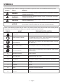 5
5
-
 6
6
-
 7
7
-
 8
8
-
 9
9
-
 10
10
-
 11
11
-
 12
12
-
 13
13
-
 14
14
-
 15
15
-
 16
16
-
 17
17
-
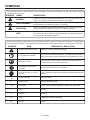 18
18
-
 19
19
-
 20
20
-
 21
21
-
 22
22
-
 23
23
-
 24
24
-
 25
25
-
 26
26
-
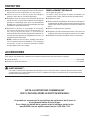 27
27
-
 28
28
-
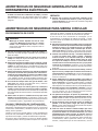 29
29
-
 30
30
-
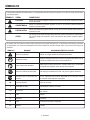 31
31
-
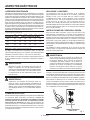 32
32
-
 33
33
-
 34
34
-
 35
35
-
 36
36
-
 37
37
-
 38
38
-
 39
39
-
 40
40
-
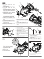 41
41
-
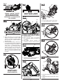 42
42
-
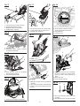 43
43
-
 44
44


RIDGID 7 1/4" Wormdrive Saw Manuel utilisateur
- Catégorie
- Coupeuses universelles de puissance
- Taper
- Manuel utilisateur
- Ce manuel convient également à