AVENTICS Series NL Assembly Instructions
- Taper
- Assembly Instructions

Montageanleitung | Assembly instructions | Mode d'emploi |
Istruzioni di montaggio | Instrucciones de montaje
Befestigungselemente
Mounting elements
Eléments de fixation
Elementi di fissaggio
Elementos de fijación
NL1
R412003503/03.2016
Replaces: 04.2014, DE/EN/FR/IT/ES
AVENTICS GmbH
Ulmer Straße 4
30880 Laatzen, GERMANY
Phone +49 (0) 5 11-21 36-0
Fax: +49 (0) 511-21 36-2 69
www.aventics.com
Further addresses:
www.aventics.com/contact
The data specified above only serve to
describe the product. No statements
concerning a certain condition or suitability
for a certain application can be derived from
our information. The given information does
not release the user from the obligation of
own judgement and verification. It must be
remembered that our products are subject
to a natural process of wear and aging.
An example configuration is depicted on the
title page. The delivered product may thus
vary from that in the illustration.
Translation of the original operating
instructions. The original operating
instructions were created in the German
language.
R412003503–BAL–001–AC/03.2016
Subject to modifications. © All rights
reserved by AVENTICS GmbH, even and
especially in cases of proprietary rights
applications. It may not be reproduced or
given to third parties without its consent.
AVENTICS | NL1 |
R412003503–BAL–001–AC 1
Deutsch
Montage
Diese Montageanleitung enthält wichtige Informationen,
um den Befestigungswinkel und den
Befestigungsbausatz der Serie NL1 sachgerecht zu
montieren, sowie Module der Serie NL1 mit dem
Verblockungssatz sachgerecht zu verbinden.
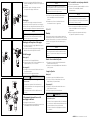
Befestigungswinkel montieren
1. Befestigungswinkel (a) von oben über den Einstellkopf
schieben.
2. Schalttafelmutter (b) über den Einstellkopf schieben
und anziehen.
Befestigungsbausatz
Montage (I)
1. Befestigungsbausatz (a) von der Seite einschieben.
2. Schiebekeil von hinten mit einem spitzen Gegenstand
(z.B. Schraubenzieher) hinein drücken.
Demontage (II)
1. Schiebekeil von der Seite mit einem spitzen
Gegenstand nach hinten schieben.
2. Befestigungsbausatz seitlich heraus ziehen.
Module mit Verblockungssatz verbinden
1. Dichtungsring einlegen.
2. Koppelklammern (a) in die vorgesehenen Bohrungen
eines Moduls (b) stecken und waagrecht ausrichten.
3. Das zweite Modul (c) parallel zum ersten Modul (b)
ausrichten und auf die Koppelklammern stecken.
4. Koppelklammern nach unten klappen.
Die Koppelklammern rasten ein.
ACHTUNG
Diese Montageanleitung ersetzt nicht die Bedienungs-
anleitung anderer Komponenten der Serie NL1.
Beachten Sie immer die beiliegenden Anleitungen.
VORSICHT
Gefahr bei falscher Einbaulage und
Durchflussrichtung
O Filter, Filterregler und Öler in Wartungseinheiten
oder als Einzelgerät nur in senkrechter Lage
einbauen.
O Die auf den Modulen gekennzeichnete
Durchflussrichtung (a) beachten.
ACHTUNG
Die Koppelklammern (a) haben unterschiedlich lange
Einsteckstifte. Den kurzen Einsteckstift immer in
Richtung der Pfeilspitze der Durchflussrichtung (siehe
Abb. oben) einstecken.
English
Assembly
These assembly instructions contain important
information on properly assembling the NL1 series
mounting bracket and mounting kit, as well as properly
linking NL1 series modules with the block assembly kit.
Assembling the mounting bracket
1. Slide the mounting bracket (a) over the setting head
from above.
2. Slide the control panel nut (b) over the setting head and
tighten.
Mounting kit
Assembly (I)
1. Insert the mounting kit (a) from the side.
2. Push the sliding wedge in from the rear with a pointy
object (e.g. screwdriver).
Disassembly (II)
1. Push the sliding wedge to the rear with a pointy object
from the side.
2. Pull the mounting kit out from the side.
Linking modules with block assembly kit
1. Insert sealing ring.
2. Insert the coupling clips (a) in the provided holes in the
module (b) and align horizontally.
3. Align the second module (c) parallel to the first module
(b) and place on the coupling clips.
4. Fold the coupling clips down.
The coupling clips will engage.
NOTICE
These assembly instructions do not replace the
operating instructions for other NL1 series components.
Always observe the enclosed instructions.
CAUTION
Wrong installation and flow direction are potentially
hazardous.
O Install filters, filter regulators, and lubricators in
maintenance units or as individual units only in
vertical position.
O Adhere to the flow direction (a) marked on each
module.
NOTICE
The coupling clips (a) have pins with different lengths.
Always insert the short pin in the direction of the arrow
for the flow directoin (see Fig. above).
Français
Montage
Cette notice de montage contient des informations
importantes permettant de monter correctement
l'équerre de fixation et le jeu d'équerres de fixation de la
série NL1, ainsi que des informations permettant de
raccorder correctement les modules de la série NL1 avec
le jeu de montage en batterie.
Monter l'équerre de fixation
1. Par le haut, faire glisser l'équerre de fixation (a) par-
dessus le bouton de réglage.
2. Introduire l'écrou de pupitre (b) par-dessus le bouton
de réglage et le serrer.
Jeu d'équerres de fixation
Montage (I)
1. Introduire le jeu d'équerres de fixation (a) par le côté.
2. Pousser la cale par l'arrière à l'aide d'un objet pointu
(p. ex. un tournevis) et l'enfoncer.
Démontage (II)
1. À l'aide d'un objet pointu, repousser la cale vers
l'arrière.
2. Sortir le jeu d'équerres de fixation par le côté.
Raccorder des modules avec le jeu de
montage en batterie
1. Placer une bague d'étanchéité.
2. Introduire les agrafes de couplage (a) dans les trous
prévus à cet effet sur un module (b), puis les orienter
horizontalement.
REMARQUE
Cette notice de montage ne remplace pas le mode
d'emploi des autres composants de la série NL1. Il est
impératif de toujours respecter les modes d'emploi ci-
joints.
ATTENTION
Risque en cas de position de montage et de sens de
flux incorrects.
O Monter les filtres, filtres régulateurs et lubrificateurs
dans les unités de traitement de l’air ou en tant
qu’appareil individuels uniquement à l’horizontale.
O Respecter le sens de flux (a) indiqué sur les
modules.
REMARQUE
Les agrafes de couplage (a) possèdent des goujons de
longueur différente. Toujours introduire le petit goujon
dans le sens de la pointe de la flèche indiquant le sens
du débit (voir Fig. en haut).
La page est en cours de chargement...
-
 1
1
-
 2
2


AVENTICS Series NL Assembly Instructions
- Taper
- Assembly Instructions
dans d''autres langues
- italiano: AVENTICS Series NL
- English: AVENTICS Series NL
- español: AVENTICS Series NL
- Deutsch: AVENTICS Series NL
Documents connexes
-
AVENTICS Series NL1 / NL2 / NL4 / NL6, 3/2 shut-off valve, 3/2-way valve, filling valve Le manuel du propriétaire
-
AVENTICS Series NL1 / NL2 / NL3 / NL4 / NL6, Regulator, filter pressure regulator Le manuel du propriétaire
-
-
-
-