
795-93851 1 of 49 12/15/21
CLEAN-O-MATIC® PARTS CLEANER – SOLVENT
Models COM304, COM504, COM604, COM804,
COM904, COM924
Operations and Maintenance Instructions
Graymills Corporation
2601 S. 25th Ave., Broadview, IL 60155
www.graymills.com

795-93851 2 of 49 12/15/21
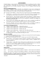
SHIPPING INFO
Unpacking and Inspection
You should inspect your equipment for possible shipping damage.
Thoroughly check the equipment for any damage that might have occurred in transit, such as broken or
loose wiring and components, loose hardware, and mounting screws, etc.
In the Event of Shipping Damage
According to the contract terms and conditions of the Carrier, the responsibility of the Shipper ends at
the time and placement of shipment.
Notify the transportation company’s local agent if you discover damage.
Hold the damaged goods and packing material for the examining agent’s inspection. Do not return
any goods before the transportation company’s inspection and authorization.
File a claim with the transportation company. Substantiate the claim by referring to the agent’s report.
A certified copy of our invoice is available upon request. The original Bill of Lading is attached to our
original invoice. If the shipment was prepaid, write us for a receipted transportation bill.
Advise customer service regarding your wish for assistance and obtain an RMA (return material
authorization) number.
If the Shipment is Not Complete
Check the packing list as back-ordered items are noted on the packing list. You should have:
• Bill of lading
• Packing list
• User’s Manual
Re-inspect the container and packing material to see if you missed any smaller items during unpacking.
If the Shipment is not Correct
If the shipment is not what you ordered, contact the parts and service department immediately. Have
the order number and item number available. Hold the items until you receive shipping instructions.
Returns
Do not return any damaged or incorrect items until you receive shipping instructions from the customer
service department.

795-93851 3 of 49 12/15/21
INTRODUCTION
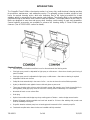
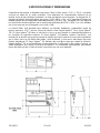
The Graymills Clean-O-Matic solvent parts washer is a heavy duty, multi-functional cleaning machine
for production, maintenance, and automotive service. The pumping system circulates solvent to both
hoses for manual cleaning action, while also delivering flow to the hydro-jet manifold for in-tank
agitation, which is convenient for more passive soak cleaning. The cleaning fluid is also continuously
circulated through a filter with a mesh screen to trap finer particles. The unique features of the Clean-O-
Matic are designed to save time and money when cleaning a wide variety of parts and assemblies.
Several optional accessories are available to enhance the cleaning ability of Clean-O-Matic parts
cleaners. (See ACCESSORIES section for details).
Standard Features
• Extra-long Stay-Put flexible metal flush hose for directed hands-free flushing action
• Pistol grip spray nozzle is adjustable for light spray or solid stream – direct where cleaning and rinsing of
parts is needed
• Pistol grip spray nozzle is adjustable for light spray or solid stream – direct where cleaning is required
• Adjustable bi-level work shelves
• Safety lid shuts automatically in the event of a fire – can also be closed to reduce fluid evaporation
• Hydro-Jet Manifold in-tank agitation loosens dirt and grime as parts soak
• Three-way cleaning action selector valve (all models except 304) permits use of hydro-jet manifold for in-
tank agitation, pistol grip spray nozzle or flush hose cleaning actions individually or in combination
• Washable 40 mesh screen solvent filter
• Drain plug
• Optional removable soak/sludge trays keep soaking parts off bottom – makes sludge removal easier
• Rugged 16-gauge minimum welded steel tank leak tested for 24 hours after welding with powder-coat
finish for durability and long-life
• Graymills abrasive-resistant pump has no bearings/seals immersed in fluid – extends pump life
• Freeboard compliant when lower shelves are installed and fully extended

795-93851 4 of 49 12/15/21
SAFETY WARNINGS / CAUTIONS
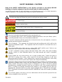
Read all the SAFETY INSTRUCTIONS on the machine and those in the manual BEFORE
installing or using this equipment. Keep this manual handy for reference/training.
You will find various types of safety information on the following pages and on the labels attached to
Graymills equipment. The following Safety Statements explain their meaning.
This is the safety alert symbol. It is used to alert you to potential personal injury hazards. Obey
all safety messages that follow this symbol to avoid personal injury or death.
DANGER indicates a hazardous situation which, if not avoided, will result in death
or serious injury.
WARNING indicates a hazardous situation which, if not avoided, could result in
death or serious injury.
CAUTION, used with the safety alert symbol, indicates a hazardous situation which,
if not avoided, could result in minor or moderate injury.
CAUTION, without the safety alert symbol, is used to address practices not related
to personal injury.
Read and understand the user manual before operating this unit.
Do not operate above 100°F (38°C) maximum ambient temperature, near open flames, sparks,
or smoking materials. Keep cover closed when unattended.
To provide continued protection against risk of electrical shock, fire, and explosion, connect to
properly grounded supply or outlets only.
Risk of explosion. This equipment has internal arcing and sparking parts, which shall not be
exposed to flammable vapors. This equipment shall not be located in a recessed floor are or
below grade.
Only cleaning fluids with a flash point at or above 104°F (40°C) shall be used. Refer to user
manual for a list of solvents which have been evaluated for use.
Do NOT contaminate cleaning solution with fluids below 104°F (40°C) flash point including
gasoline, alcohol, or other flammable liquids. Even small amounts will create a hazardous
condition.
Ensure fusible link and closing device are in proper working order. Fusible link melts at
165°F(74°C) causing lid to close. When open the lid must lean forward so it will close
automatically when link melts. Do NOT tamper with or remove the fusible safety link. If the safety
link breaks or is lost, do NOT use the unit. Replace the safety link immediately.
Hazardous voltage present. Disconnect power before repairing or cleaning. Unit must be properly
grounded to prevent electric shock, fire, and explosion hazard. Connect only to three prong
outlets. Should cord become cracked, frayed, or damaged in any way, it should be repaired
immediately by a qualified electrician. Never use an extension cord. Since operator safety at all
times is a priority, we strongly recommend that, whether or not required by local code, this
equipment be connected only into a power supply equipped with a “Ground Fault Interrupter”
(GFI). All electrical connections should conform to national/local codes and be made by qualified
personnel.
Do not leave objects in the tank or let hose attachments exit the tank which prevent lid from
closing completely in the event of fire.

795-93851 5 of 49 12/15/21
Do not operate below minimum liquid level marking. Low liquid level may result in motor failure,
creating a potential fire hazard. Fill tank to recommended operating capacity range before
plugging in power cord Do not operate with tank empty.
Operator shall wear appropriate PPE (personal protective equipment). Refer to cleaning fluid
SDS (safety data sheet) for details. If any cleaning solutions are splashed on clothing, remove
wet clothing promptly and thoroughly wash body areas that have been in contact with the
solution. Do NOT permit saturated clothing to remain in contact with skin. Cleaning solutions may
irritate skin and eyes. If splashed in eyes, flush thoroughly with water. Consult Safety Data Sheet
(SDS) and a physician. Always wear appropriate safety items such as gloves, apron, safety
glasses or goggles.
Floor may be slippery when wet, do not splash fluids out of tank.
Use with solvent cleaning fluids only. The use of aqueous based (water) cleaning fluids will
damage the finish and cause rusting.
Install unit on level surface. Do not overload tank floor, shelf, or trays. Load items evenly, do not
allow items to overhang outside tank.
Never work with equipment you feel may be unsafe. Contact your supervisor immediately if you
feel a piece of equipment is in an unsafe condition.
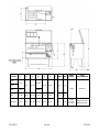
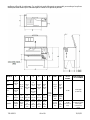
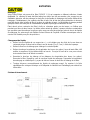
SPECIFICATIONS AND DIMENSIONS
Depending on the model, the Clean-O-Matic parts cleaner operates at either 115V or 230V or can be
powered by an air motor. To determine the electrical requirements of your model, check the nameplate
located on the side of the tank near the motor. An “A” designation after the model number indicates it
operates at 115V, 60 Hz, 1 ph. A “B” following the model number means the unit is rated at 230V, 60
Hz, 1 ph. A “GG” following the model numbers means the unit is rated at 230V, 50Hz, 1 ph. Air-
powered units are designated with a -GAM suffix.
The Clean-O-Matic is designed to be used with combustible (flash point over 104°F) petroleum-based
cleaning fluids such as Regular Agitene® 141 or Super Agitene® 141. Super Agitene® 141 has a mild,
fresh odor and is far superior in cleaning ability than normal safety solvents. Super Agitene® 141 also
contains "HandEase," a lanolin formulation that helps prevent skin irritation, plus seven other
ingredients that make it a unique cleaning fluid that cleans faster, more easily and lasts longer than
other cleaning fluids. Super Agitene® 141 also leaves a light rust retarding film. Regular Agitene® 141
is a fast-drying, film-free cleaner which contains Tergene, a detergent additive for better cleaning efficiency.
It is especially recommended for cleaning electrical parts since it will not harm varnish and parts to be
painted.

795-93851 6 of 49 12/15/21
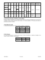
MODEL
A
B
C
D
E
F
G
MAX
MIN
PUMP
POWER
PUMP
PERFORMANCE
304
44"
21"
58.13"
32.38"
19.63"
23.63"
37"
10"
5.13"
1/3HP
2400GPH
504
604
60"
48.38"
804
41.38"
29.31"
66.14"
29.76"
27.94"
29.5"
15"
9"
904/924
49"
30"
67.13"
37.35"
29.13"
32.35"
17"
6.13"
1/3HP
(x1 904,
x2 924)
2400GPH (904)
4800GPH (924)

795-93851 7 of 49 12/15/21
Air Motor (GAM) Characteristics
There is no pilot light or switch. The air connection is on the side of the tank with the valve. Minimum
60PSI air supply required with motor set at 1725RPM to have full pump performance.
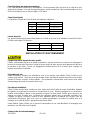
Liquid Capacities
The liquid capacity of your Clean-O-Matic is as indicated below:
Model
Maximum
Minimum
304, 504
40 gals
20 gals
604
54.5 gals
28 gals
804
81.5 gals
49 gals
904, 924
109.5 gals
39.5 gals
Weight Limitations
The maximum weights which can be placed on the tank bottom and work shelves of your Clean-O-
Matic are indicated below:
Model
Bottom
Shelves
304, 504, 804
500 lbs.
150 lbs.
904, 924
750 lbs.
200 lbs.
INSTALLATION AND OPERATION
The work area should be well ventilated.
Provide adequate lighting in the work area to allow observation of the cleaning process and the floor
area around the machine. Be sure to allow adequate room to bring work to and from the machine.
Provide sufficient clearance around the machine for fluid changeovers and servicing.
Site Preparation
Before installing, careful consideration should be given to the place of operation. Place unit on a
smooth, level surface. To the extent possible avoid installing machine in areas subject to high forklift
traffic. Reasonable precautions shall be taken to avoid damaging the legs and tank walls.
Installation Procedure
The Clean-O-Matic is very easily put into operation. After removing it from its shipping carton, unpack
any trays and accessory components from inside the tank. Assemble the handle to the cover, and
install any parts shelfs (this will ensure freeboard compliance). Check to be sure drain plug is tightened,
fill with the desired amount of an appropriate cleaning fluid (see Liquid Capacities, above) and insert the
3-prong plug into the proper receptacle (see electrical specifications above). If using an air motor,
attach airline hose to valve on side of unit and the unit is ready for use.
Before operating your Clean-O-Matic, read the following descriptions of its features and benefits to
maximize efficiency and longevity from your unit.
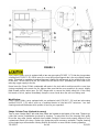
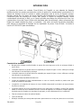
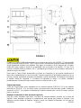
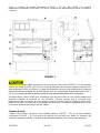
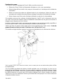
Automatic Safety Cover
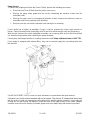
Open the automatic Safety Cover (FIGURE 1 (A)) on your Clean-O-Matic and you will notice that it lifts
simply and easily with one hand. There is nothing to connect or disconnect to open or close the cover.

795-93851 8 of 49 12/15/21
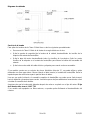
FIGURE 1
Your Clean-O-Matic cover is equipped with a two-way gas spring(FIGURE 1 (C)) that also incorporates
a fusible link (FIGURE 1 (B)). When open, the cover mechanism supports the cover at a slightly forward
angle. This angle is necessary to assure the cover’s fusible link will operate in the unlikely event of fire
in the tank. In the event of a fire, the fusible link will melt at 165°F permitting the lid to slam shut,
reducing oxygen supply to the fire.
Never leave the Clean-O-Matic unattended with parts in the tank which would prevent the cover from
closing completely in the event of a fire. Always make sure that the cover remains in its correct, slightly
tilted forward position when open. Do NOT tamper with or remove the fusible safety link. If the safety
link breaks or is lost, replace immediately. Keep the cover closed when the unit is not being used.
Work Shelves
Every Clean-O-Matic comes equipped with one perforated shelf (FIGURE 1 (D)) and two telescoping
shelves(FIGURE 1 (E)) which serve as a freeboard barrier to help limit VOC emissions. Your own
cleaning needs will determine which position is best for your operation.
Sludge Collector Trays (Optional Accessory)
Two or more “sludge trays” with side foam filters are located at the bottom of the tank. These trays
collect the heavier contamination produced by cleaning. To extend the life of the cleaning fluid, gently
lift out the trays after heavier materials have settled overnight. Remove and properly dispose of any
contaminants found in the trays. Replace the sludge trays and commence operation. Regular cleaning
of the sludge trays will maximize cleaning fluid life and result in a more efficient cleaning operation.

795-93851 9 of 49 12/15/21
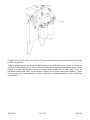
Pumping Unit
The centrifugal pumping unit (FIGURE 1 (F)) supplied with the Clean-O-Matic is a rugged “machine
tool” quality unit that is a valuable aid in parts cleaning. It is particularly useful in flushing away
softened grease and grime after parts have been soaked.
Pump and Tank Agitation
To operate the pump and tank agitation after filling, turn on the switch (FIGURE 1 (G)) on the front of
the Clean-O-Matic or turn valve for air. The green pilot light should go on, indicating that the pump is
running. On all models, the small valve on the flexible metal hose (FIGURE 1 (J)) allows you to cut off
flow to the flexible hose, directing all fluid through the spray hose (FIGURE 1 (K)). Always direct flow
into tank in such a way as to avoid splashing. Never point spray nozzle at anyone. On Models 504
through 924, the Selector Valve (FIGURE 1 (H)) is located on the inside rear-right hand side of the
tank. The Selector Valve permits use of tank agitation alone, the flush and spray hoses together, or a
combination of all three.
When using the Tank Agitation setting, align parts in the tank so that the maximum area of the parts or
any cavities in the parts are exposed as fully as possible to the fluid emitted from the jet nozzles. To
minimize fluid evaporation, keep the tank cover closed during agitation.
All models:
• Never work with equipment you feel may be unsafe. Contact your supervisor immediately if you
feel a piece of equipment is in an unsafe condition.
• Fill tank with Graymills Regular Agitene® 141/Super Agitene® 141 or comparable cleaning fluid
with a flash point of 104°F (40°C) or higher.
• Insert plug into a properly grounded compatible outlet. For air-powered units the tank should be
connected to ground to dissipate static electricity.
• Turn on rocker switch on right side of tank to start fluid recirculating.

795-93851 10 of 49 12/15/21
MAINTENANCE
Cleaning
Your Clean-O-Matic is equipped with a filter (FIGURE 1 (L)) with a reusable screen collector element.
This screen collector should be cleaned at least once a week, more often in heavy use, in order to help
extend the life of the cleaning fluid and increase cleaning efficiency. Periodically, an oil filter cartridge
(see spare parts list below) can be placed in the filter canister in place of the screen collector. Running
the pump for a few hours will pull more contaminants out of the fluid and help extend fluid’s usable life.
Since an oil filter cartridge will clog within a short time, use for only one or two hours at the most.
Removing as much excess dirt, chips, and other contaminants as possible before cleaning dirty parts
will extend the life of the cleaning fluid. Another way to extend fluid life is to use Graymills Solvent
Savers. Contact Customer Service for further details.
Changing Fluid
• Remove the flexible hose from the "L" support bracket, aim it over the tank sides into a proper
container and remove all but the last 1” of solvent using the pump.
• Remove drain plug to drain remaining fluid.
• Remove and clean the optional sludge trays. Wash the 40-mesh screen solvent filter and replace
the gasket if necessary. Wipe out the bottom of the tank to remove any accumulated sludge and
debris still remaining.
• Replace the drain plug and optional sludge trays. Reassemble the filter. Refill the tank with fresh
cleaning fluid. Resume cleaning operations, checking for leaks at the drain plug and filter.
• Always dispose of used cleaning fluid properly. Refer to the cleaning chemical SDS (safety data
sheet) and manufacturer's package label for instructions.
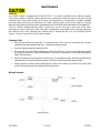
Wiring Schematic

795-93851 11 of 49 12/15/21
Pump Service
To remove the pumping units from the Clean-O-Matic, perform the following procedures:
• Disconnect the Clean-O-Matic from the power or air source.
• Remove the pump safety guard from the unit by unfastening the machine screws from the
motor/filter shelf.
• Remove the motor cover by unscrewing all machine screws. Remove four machine screws on
motor/filter shelf to free up pump shelf assembly.
• Remove each wire nut from the electrical cord and tag for re-assembly.
If your model has a Hydro-Jet manifold (1” pipe), it can be removed by using a pipe wrench to
loosen. Swing (from back end) motor/filter shelf to the left to allow enough room for pipe wrench.
With the pipe removed, the whole pump/filter assembly can be swung (back end) to the left and lifted
out. Reverse the procedure when replacing the pump assembly.
Ensure pump shaft alignment after re-coupling with motor shaft. Pump shaft must have ≤ 0.005” TIR.
If your model is equipped with external filters, they can be removed simply be unscrewing them from
the manifold:
See REPLACEMENT PARTS section for more information on replacement filter part numbers.
All models have double suction impellers with no set screws. They have a “D” shaped hole that is flush
with the shaft. A castle nut compresses shaft springs which adjusts impeller clearance. Insert cotter pin
to keep the nut from turning. All impellers should be close to the upper surface of the volute (impeller
chamber) and checked for rubbing. Assemble gasket and cover plates firmly with fasteners provided.

795-93851 12 of 49 12/15/21
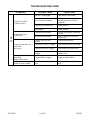
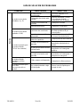
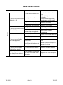
TROUBLESHOOTING GUIDE
CONDITION
POSSIBLE CAUSE
CORRECTION
Pump
Pump does not run
(-A and -B units)
Machine is unplugged
Plug machine into outlet
Circuit breaker is tripped
Check breaker and correct.
If problems persist, contact
Graymills.
Pump motor is burned out
Replace pump
Faulty switch
Replace switch
Pump does not run
(-GAM units)
Insufficient air pressure
Ensure air pressure is set to 60
psi min
Air motor vanes seized
Inject 5 drops #10 oil into air
motor inlet
Pump runs but does not
pump fluid
(ALL units)
Selector valve is out of
position
Correct valve position
Pump filter screen is clogged
Clear debris from around pump
Flexible metal hose clogged
Clear debris from metal hose
Pump rubber discharge hose
clogged
Clear debris from hose or
replace hose
Pump runs but does not
pump fluid
(External filter units)
External filter is clogged
Replace external filters
Pump runs but is noisy
(Some noise is normal).
Cavitation due to low liquid
level
Raise liquid level to correct
level

795-93851 13 of 49 12/15/21
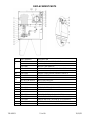
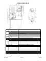
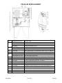
REPLACEMENT PARTS
#
PART NUMBER
DESCRIPTION
1
325-93806
MOTOR (-A & -B MODELS) 1/3 HP
387-07248
MOTOR (-GAM MODELS) 1/3 HP
325-93807
MOTOR (-GG MODELS)
9
525-13607-74
PUMP IMPELLER (ALL MODELS EXCEPT 904/924)
525-13710-74
PUMP IMPELLER (904/924)
10
744-13709
GASKET,FIBER PAPER,30SERIES VOLUTE
15
744-13987
FILTER GASKET
19
742-14088-13
FILTER SCREEN
FILTER CARTRIDGE
WIX 51076 OR EQUAL
24
728-02657
NEOPRENE HOSE
25
738-02927
PISTOL GRIP NOZZLE
26
728-04102
FLEXIBLE METAL FLUSH HOSE
29
740-93713
FUSIBLE LINK 165°F
32
765-09631
GAS SPRING
770-93609
ROCKER SWITCH, I/O (ALL MODELS)
772-92079
INDICATOR LIGHT, GREEN (-A & -GAM MODELS)
772-93703
INDICATOR LIGHT, GREEN (-B & -GG MODELS)
742-93510-03
FILTER,HYDRA.SPIN-ON,10.75LG,3 MIC
742-93510-08
FILTER,HYDRA.SPIN-ON,10.75LG,8 MIC

795-93851 14 of 49 12/15/21
ACCESSORIES
Graymills manufactures a wide variety of parts cleaning supplies and accessories for use with your
Clean-O-Matic. Contact your Graymills Jobber or Distributor for more information on the items listed
below. (See Catalog GM100 for additional items)
Parts Cleaning Brushes
Graymills parts cleaning brushes are specifically designed for tough parts cleaning work. The crimped
nylon fibers outwear ordinary brushes and won't ball up, flare out, or get flabby.
3B-G Standard Nylon Brush — 2-1/2” nylon bristles for maximum durability.
5D Double Brush — 2-1/2” nylon bristle brush for broad cleaning at one end of the tapered handle
and a 1-1/2” fine brush at the other.
6A Flow-Thru Brush – flushes parts as they are cleaned. Solvent flows through the core of the
handle. Manufactured with a 2’ connecting hose, 2·1/2” nylon bristles, and a rubber connector
which slips over the nozzle of the flexible metal hose.
7A Flat Angular Flow-Thru cleaning brush with polyester bristles; can attach to pump nozzle with
included hose. Plastic Handle.
8A Round Angular handle cleaning brush with polyester bristles; can attach to pump nozzle with
included hose. Plastic handle.
Parts Cleaning Accessories
L-4 Extra work shelf — Model 804 only.
L-4S Extra work shelf — Model 804 only; solid metal.
L-5 Extra work shelf — Models 304, 504.
L-5S Extra work shelf — Models 304, 504, and 604; solid metal.
L-6 External Drain Shelf — 16” x 18”, hooks into position at left side of the tank to permit solvent to
drain back.
For all models
432-36376 Sludge Tray - For use with 304, 504 and 604 Series (2 required) or 804 Series (3 required)
432-36664 Sludge Tray - For use with 904 Series (2 required)
L-8 Parts Basket — 16-gauge metal bottom and sides, solid metal ends. Measures 13” L x 12” W x
5” H. Fits on L-6 drain shelf.
L-9
Parts Basket — 15-gauge frame with metal sides and bottom. Measures 32” L x 17” W x 5” H.
Can be supported above liquid level for parts draining by special pullout supports.
L-9L Parts Basket — Same as L-9 with the addition of a lifter bar for use with chain hoists.
Solvent Savers
Oil and Grease Removal (Packed two/carton)
SS-11 7" diameter x 11" long–includes one connecting hose
SS-18 7" diameter x 18" long–includes one connecting hose
Oil and Grease Plus Particulate Removal (Packed two/carton) In addition to special absorbent
materials, it contains a 5-micron filter cartridge that filters particulate from the solvent prior to oil and
grease absorbing stage.
SSC-11 7" diameter x 11" long–includes one connecting hose
SSC-18 7" diameter x 18" long-includes one connecting hose
Solvent Saver Hanging Bracket-Stainless Steel bracket holds filter out of way on inside of parts washer.
SS-BRAC 12" long x 9" deep X 8" high

795-93851 15 of 49 12/15/21
WARRANTY INFORMATION
Graymills Corporation warrants that the equipment manufactured and delivered, when properly
installed and maintained, shall be free from defects in workmanship and will function as quoted in the
published specification. Graymills does not warrant process performance, nor assume any liability for
equipment selection, adaptation, or installation.
Warranty does not apply to damages or defects caused by shipping, operator carelessness, misuse,
improper application or installation, abnormal use, use of add-on-parts or equipment which damages or
impairs the proper function of the unit, and modifications made to the unit. Warranty does not apply to
expendable parts needing replacement periodically due to normal wear and tear.
A new Warranty period shall not be established for repaired or replaced materials or products. Such
items shall remain under Warranty for only the remainder of the Warranty period of the original material
or product.
THE FOREGOING WARRANTIES ARE IN LIEU OF ALL OTHER WARRANTIES, WHETHER ORAL,
WRITTEN, EXPRESSED, IMPLIED OR STATUTORY. GRAYMILLS CORPORATION MAKES NO
OTHER WARRANTY OF ANY KIND, EXPRESS OR IMPLIED. ALL IMPLIED WARRANTIES OF
MERCHANTABILITY AND FITNESS FOR A PARTICULAR PURPOSE WHICH EXCEED THE
AFORESTATED OBLIGATION ARE HEREBY DISCLAIMED BY GRAYMILLS CORPORATION AND
EXCLUDED FROM THIS SALE. Graymills warranty obligations and Buyer remedies (except to title),
are solely and exclusively stated herein. In no case will Graymills be liable for consequential damages,
loss of production, or any other loss incurred due to interruption of service.
Graymills' obligation under this Warranty shall be limited to:
1. Repairing or replacing (at Graymills sole discretion) any non-conforming or defective
component within one year from the date of shipment from Graymills.
2. Repairing or replacing (at Graymills sole discretion), components supplied by, but not
manufactured by Graymills, to the extent of the warranty given by the original manufacturer.
3. This warranty does not cover rusting of a mild-steel parts cleaner used with aqueous (water-
based) materials. Buyer must give Graymills prompt notice of any defect or failure.
Buyer must give Graymills prompt notice of any defect or failure.
If you believe you have a Warranty claim, contact Graymills at (773) 477-4100. Any return material
must have an RMA number on the outside of the package and shipping prepaid or shipment will be
refused. Graymills will promptly examine the material and determine if it is defective and within the
Warranty period.

795-93851 16 of 49 12/15/21
This page intentionally left blank.

795-93851 17 of 49 12/15/21
CLEAN-O-MATIC® LIMPIADORA DE PIEZAS –
SOLVENTE
Modelos COM304, COM504, COM604, COM804,
COM904, COM924
Instrucciones de operación y mantenimiento
Graymills Corporation
2601 S. 25th Ave., Broadview, IL 60155
www.graymills.com

795-93851 18 of 49 12/15/21
INFORMACIÓN DE ENVÍO
Desempacado e inspección
Debe inspeccionar su equipo por posibles daños durante el envío.
Revise minuciosamente el equipo para detectar cualquier daño que pueda haber ocurrido durante el
transporte, por ejemplo, componentes y cables sueltos o rotos, herrajes o tornillos de montaje sueltos,
etc.
En caso de daños durante el envío
De conformidad con los términos y condiciones de contrato del transportista, la responsabilidad del
expedidor termina al momento de hacer el envío.
En caso de que encuentre daños, notifique al agente local de la empresa transportista.
Guarde la mercancía dañada y el material de empaque para que el agente de revisión lo inspeccione.
No devuelva ninguna mercancía antes de la inspección y autorización por parte de la empresa
transportista.
Presente un reclamo ante la empresa transportista. Fundamente el reclamo haciendo referencia al
reporte del agente. Tiene disponible una copia certificada de su factura cuando usted la solicite. La
hoja de envío original está adjunta a nuestra factura original. Si el envío fue prepagado, contáctenos
para obtener el recibo de transporte.
Avise a servicio al cliente en caso de que desee recibir asistencia y obtener un número de autorización
de devolución de material (RMA, por sus siglas en inglés).
Si el envío no está completo
Revise el manifiesto de carga, ya que los artículos que se envían sobre pedido están indicados en el
manifiesto de carga. Usted debe tener lo siguiente:
• Hoja de envío
• Manifiesto de carga
• Manual del usuario
Vuelva a inspeccionar el contenedor y material de empaque para verificar que no haya pasado por alto
ningún artículo pequeño durante el desempaque.
Si el envío no es correcto
Si el envío que recibió no está de acuerdo con lo que usted pidió, comuníquese con el departamento
de piezas y servicio inmediatamente. Tenga el número de pedido y el número de artículo a la mano.
Guarde los artículos hasta que reciba instrucciones para su envío.
Devoluciones
No devuelva ningún artículo dañado o incorrecto hasta que reciba instrucciones para el envío de
devolución por parte del departamento de servicio al cliente.

795-93851 19 of 49 12/15/21
INTRODUCCIÓN
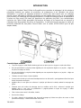
La lavadora de piezas con solvente Clean-O-Matic de Graymills es una máquina de limpieza
multifuncional de uso pesado para tareas de servicio de producción, mantenimiento y automotrices. El
sistema de bombeo circula el solvente a ambas mangueras para la acción de limpieza manual,
mientras entrega flujo al colector de chorro hidráulico para la agitación en el depósito, una función
conveniente para una limpieza por remojo más pasiva. El líquido de limpieza también circula
continuamente a través de un filtro con un cedazo de malla para atrapar las partículas más finas. Las
características únicas del Clean-O-Matic están diseñadas para ahorrar tiempo y dinero al momento de
limpiar una amplia variedad de piezas y ensambles. Hay varios accesorios opcionales disponibles
para mejorar la capacidad de limpieza de las limpiadoras de piezas Clean-O-Matic. (Consulte la
sección ACCESORIOS para más detalles).
Características estándar
• Manguera de enjuague metálica flexible de puesta fija extra larga para acción de enjuague dirigido a
manos libres
• La boquilla aspersora de pistola manual es ajustable para aspersión ligera o chorro sólido que se dirige
hacia donde se necesita limpiar y enjuagar
• La boquilla aspersora de pistola manual es ajustable para aspersión ligera o chorro sólido que se dirige
hacia donde se necesita limpiar
• Estantes de trabajo ajustables de doble nivel
• La tapa de seguridad se cierra automáticamente en caso de incendio, también se puede cerrar para
reducir la evaporación del líquido
• La agitación en el depósito del colector de chorro hidráulico desprende la suciedad y la mugre mientras
las piezas se remojan
• La válvula selectora de acción de limpieza de tres vías (para todos los modelos, excepto 304) permite
utilizar el colector de chorro hidráulico para las acciones de agitación en el depósito, boquilla aspersora
de pistola manual o limpieza con manguera de enjuague, ya sea individualmente o en combinación
• Filtro de solvente de cedazo de malla 40 lavable
• Tapón de drenado
• Bandejas extraíbles para remojo/lodosopcionales para mantener en remojo las piezas sin tocar el fondo,

795-93851 20 of 49 12/15/21
que facilitan la remoción de lodos
• Depósito de acero soldado resistente con calibre 16 como mínimo y probado durante 24 horas después
de soldarse como resistente a las fugas, con acabado de revestimiento en polvo para larga vida y
durabilidad
• La bomba resistente a la abrasión Graymills no tiene cojinetes/sellos que se sumerjan en el líquido, lo
cual alarga la vida de la bomba
• Cumple con las normas de bordo libre cuando los estantes inferiores están instalados y totalmente
extendidos
ADVERTENCIAS / PRECAUCIONES DE SEGURIDAD
ANTES de instalar o usar este equipo, lea todas las INSTRUCCIONES DE SEGURIDAD que
vienen en la máquina y en el manual. Mantenga este manual a la mano para referencia o
capacitación.
Encontrará diferentes tipos de información sobre seguridad en las páginas siguientes y en las etiquetas
adheridas a los equipos Graymills. Las siguientes Declaraciones de seguridad explican su significado.
Este es el símbolo de alerta de seguridad. Se utiliza para ponerlo en alerta sobre posibles
riesgos de lesiones personales. Obedezca todas las indicaciones de seguridad que siguen a
este símbolo para evitar lesiones personales o la muerte.
PELIGRO significa que existe una situación de riesgo que, si no la evita, causará
lesiones graves o la muerte.
ADVERTENCIA significa que existe una situación de riesgo que, si no la evita,
podría causar lesiones graves o la muerte.
PRECAUCIÓN, utilizada junto con el símbolo de alerta de seguridad, significa que
existe una situación de riesgo que, si no la evita, podría causar lesiones menores a
moderadas.
PRECAUCIÓN, sin el símbolo de alerta de seguridad, se utiliza para indicar
prácticas que no están relacionadas con lesiones personales.
Antes de operar esta unidad lea y entienda el manual del usuario.
No opere la unidad cuando la temperatura ambiente máxima sea mayor que 100 °F (38 °C) ni
cerca de llamas, chispas o materiales humeantes. Mantenga la tapa cerrada cuando no esté en
uso.
Para mantener la protección continua contra riesgos de descarga eléctrica, incendio y explosión,
conecte la unidad a tomacorrientes o fuentes de alimentación conectadas a tierra correctamente.
Riesgo de explosión. Este equipo contiene piezas que generan arco eléctrico y chispas
internas, los cuales no deben exponerse a vapores inflamables. Este equipo no debe ubicarse
en piso desnivelado o por debajo del nivel del suelo.
Use únicamente líquidos limpiadores con punto de ignición mayor a 104 °F (40 °C). Consulte el
manual del usuario para ver la lista de solventes que ya fueron evaluados para su uso.
NO contamine la solución limpiadora con líquidos cuyo punto de ignición sea menor a 104 °F (40
°C), incluidos gasolina, alcohol u otros líquidos inflamables. Incluso pequeñas cantidades
generarán condiciones peligrosas.
Asegúrese de que el eslabón fusible y el dispositivo de cierre funcionen correctamente. El
La page est en cours de chargement...
La page est en cours de chargement...
La page est en cours de chargement...
La page est en cours de chargement...
La page est en cours de chargement...
La page est en cours de chargement...
La page est en cours de chargement...
La page est en cours de chargement...
La page est en cours de chargement...
La page est en cours de chargement...
La page est en cours de chargement...
La page est en cours de chargement...
La page est en cours de chargement...
La page est en cours de chargement...
La page est en cours de chargement...
La page est en cours de chargement...
La page est en cours de chargement...
La page est en cours de chargement...
La page est en cours de chargement...
La page est en cours de chargement...
La page est en cours de chargement...
La page est en cours de chargement...
La page est en cours de chargement...
La page est en cours de chargement...
La page est en cours de chargement...
La page est en cours de chargement...
La page est en cours de chargement...
La page est en cours de chargement...
La page est en cours de chargement...
-
 1
1
-
 2
2
-
 3
3
-
 4
4
-
 5
5
-
 6
6
-
 7
7
-
 8
8
-
 9
9
-
 10
10
-
 11
11
-
 12
12
-
 13
13
-
 14
14
-
 15
15
-
 16
16
-
 17
17
-
 18
18
-
 19
19
-
 20
20
-
 21
21
-
 22
22
-
 23
23
-
 24
24
-
 25
25
-
 26
26
-
 27
27
-
 28
28
-
 29
29
-
 30
30
-
 31
31
-
 32
32
-
 33
33
-
 34
34
-
 35
35
-
 36
36
-
 37
37
-
 38
38
-
 39
39
-
 40
40
-
 41
41
-
 42
42
-
 43
43
-
 44
44
-
 45
45
-
 46
46
-
 47
47
-
 48
48
-
 49
49


Graymills CLEAN-O-MATIC COM804 Le manuel du propriétaire
- Taper
- Le manuel du propriétaire
- Ce manuel convient également à
dans d''autres langues
Documents connexes
-
Graymills DMD336 Le manuel du propriétaire
-
-
-
-
-