
© 2019 tekmar 671
_
A - 08/19
671
_
A
08/19
Snow Melting
Replaces: New
WiFi Snow Melting Control 671
Application Brochure
Application Page
Dedicated Boiler 2
Shared Boiler and Heat Exchanger 4
On/Off Steam Valve 6
Electric Cable 8
Two Zones with Common Mixing 10
WiFi Snow Melting Control 671
Pulse Width Modulation
Power
Relays
1084-02
Designed and assembled in Canada
Date Code
H2058A
Blu
3
Yel
4
Brn/
5
Slab
Man
6
Melt
C
7
Blk/
2
Com
Red
1
Boiler Heat
Relay
System
Pump
11 12 13
Do Not Apply Power
Out
10
Com
9
tN4
8161514
Power
17
L
18
N
For product literature:
Pour la documentation du produit:
Para la literatura del producto:
tekmarControls.com
Disconnect all power before opening.
WARNING
Coupez l'alimentation avant l'ouverture.
ATTENTION
Desconecte la electricidad antes de abrir.
ADVERTENCIA
Signal wiring must be rated at least 300 V.
Le câblage du signal doit être d'une capacité d'au moins 300 V.
Cableado de señal debe tener una
calificación mínima de 300 V.
Contains WiFi transceiver:
FCC ID: Z64-CC3100M0DR1
Meets FCC Part 15B
IC: 4511-CC3100M0DR1
Meets CAN ICES-3 (B)/NMB-3(B)
115 V (ac) ±10%, 60 Hz, 20 VA
230 V (ac) 5 A 1/3 hp
This is a hole
Manual Melt
Time Left
- - : - - hrs
Outdoor
32 °F
Settings Status
System is Melting
Stop
10:30 AM
Warming Up
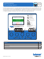
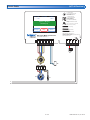
The WiFi Snow Melting Control 671 is designed to operate mechanical equipment to melt snow off an outdoor slab. It can
be used in hydronic or electric snow melting applications. This product uses a tekmar snow/ice detection sensor in order
to automatically melt snow using Pulse Width Modulation (PWM) and slab OutDoor Reset to maintain slab temperature.
It is capable of controlling a single boiler, steam valve, or electric cable to supply heat to the slab.

2 of 16
© 2019 tekmar 671
_
A - 08/19
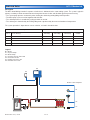
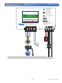
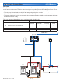
Dedicated Boiler A671-1 Mechanical
Description
The WiFi Snow Melting Control 671 operates a boiler that is dedicated for the snow melting system. The system is piped in
primary-secondary to allow constant flow rates through the low-mass boiler and filled with glycol to prevent freezing.
• The system pump operates continuously when heating the slab during melting/idling/storm operation.
• The boiler pump cycles on and off together with the boiler.
• The slab temperature is controlled by cycling the boiler on and off.
• The slab target is determined by the melting/idling/storm setpoint and by the measured outdoor air temperature.
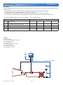
The system operation is dependent on sensor selection, as listed in the table below.
Sensor options Operation methods
Sensor
Sensor Model(s)
Auto Start/
Auto Stop
Auto Start/
Timed Stop
Manual Start/
Timed Stop
Slab Temperature
Control
S1 Automatic Snow/Ice Sensor 090 or 094 • – • •
S2 Aerial Snow Sensor 095 – • • –
S3 Slab Sensor 072 or 073 – – • •
S2+S3 Aerial Snow Sensor 095 and Slab Sensor 072/073 – • • •
B1 = Boiler
P1 = System Pump
P2 = Boiler Pump
S1 = Snow/Ice Sensor 090 or 094
S2 = Snow Sensor 095
S3 = Slab Sensor 072 or 073
S4 = Outdoor Sensor 070
Legend
S4
671
Snow/Ice Sensor Options
B1
P2
P1
S2
S1
S3

© 2019 tekmar 671
_
A - 08/19
3 of 16
TT
WiFi Snow Melting Control 671
Pulse Width Modulation
Power
Relays
1084-02
Designed and assembled in Canada
Date Code
H2058A
Blu
3
Yel
4
Brn/
5
Slab
Man
6
Melt
C
7
Blk/
2
Com
Red
1
BoilerHeat
Relay
System
Pump
11 12 13
Do Not Apply Power
Out
10
Com
9
tN4
81
61514
Power
17
L
18
N
For product literature:
Pour la documentation du produit:
Para la literatura del producto:
tekmarControls.com
Disconnect all power before opening.
WARNING
Coupez l'alimentation avant l'ouverture.
ATTENTION
Desconecte la electricidad antes de abrir.
ADVERTENCIA
Signal wiring must be rated at least 300 V.
Le câblage du signal doit être d'une capacité d'au moins 300 V.
Cableado de señal debe tener una
calificación mínima de 300 V.
Contains WiFi transceiver:
FCC ID: Z64-CC3100M0DR1
Meets FCC Part 15B
IC: 4511-CC3100M0DR1
Meets CAN ICES-3 (B)/NMB-3(B)
115 V (ac) ±10%, 60 Hz, 20 VA
230 V (ac) 5 A 1/3 hp
This is a hole
Manual Melt
Time Left
- - : - - hrs
Outdoor
32 °F
Settings Status
System is Melting
Stop
10:30 AM
Warming Up
Brn
Slab
Blk
Com
YelBluRed
Snow
Sensor
095
S4
B1
L
N
P1
S1
S2
S3
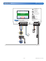
Dedicated Boiler A671-1 Electrical

4 of 16
© 2019 tekmar 671
_
A - 08/19
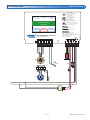
Shared Boiler and Heat Exchanger
A671-2 Mechanical
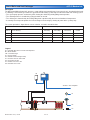
A1 = Normally Closed Freeze Protection Aquastat
B1 = Boiler Enable
HX = Heat Exchanger
P1 = System Pump
P2 = On/Off Heat Exchanger Pump
S1 = Snow/Ice Sensor 090 or 094
S2 = Snow Sensor 095
S3 = Slab Sensor 072 or 073
S4 = Outdoor Sensor 070
Legend
671
Snow/Ice Sensor Options
S4
P2
A1
P1
S1
S2
S3
HX
Description
The WiFi Snow Melting Control 671 operates a snow melting zone warmed from a heat source that is shared with other loads
in a building. A heat exchanger isolates the glycol-filled snow melting system loop from the water-filled main heating system.
• The system pump operates continuously when heating the slab during melting/idling/storm operation.
• The slab temperature is controlled by cycling the boiler on and off.
• The slab target is determined by the melting/idling/storm setpoint and by the measured outdoor air temperature.
• A normally-closed aquastat protects the heat exchanger from freezing by shutting off power to the system pump.
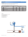
The system operation is dependent on sensor selection, as listed in the table below.
Sensor options Operation methods
Sensor
Sensor Model(s)
Auto Start/
Auto Stop
Auto Start/
Timed Stop
Manual Start/
Timed Stop
Slab Temperature
Control
S1 Automatic Snow/Ice Sensor 090 or 094 • – • •
S2 Aerial Snow Sensor 095 – • • –
S3 Slab Sensor 072 or 073 – – • •
S2+S3 Aerial Snow Sensor 095 and Slab Sensor 072/073 – • • •

© 2019 tekmar 671
_
A - 08/19
5 of 16
Brn
Slab
Blk
Com
YelBluRed
Snow
Sensor
095
WiFi Snow Melting Control 671
Pulse Width Modulation
Power
Relays
1084-02
Designed and assembled in Canada
Date Code
H2058A
Blu
3
Yel
4
Brn/
5
Slab
Man
6
Melt
C
7
Blk/
2
Com
Red
1
Boiler Heat
Relay
System
Pump
11 12 13
Do Not Apply Power
Out
10
Com
9
tN4
81
61514
Power
17
L
18
N
For product literature:
Pour la documentation du produit:
Para la literatura del producto:
tekmarControls.com
Disconnect all power before opening.
WARNING
Coupez l'alimentation avant l'ouverture.
ATTENTION
Desconecte la electricidad antes de abrir.
ADVERTENCIA
Signal wiring must be rated at least 300 V.
Le câblage du signal doit être d'une capacité d'au moins 300 V.
Cableado de señal debe tener una
calificación mínima de 300 V.
Contains WiFi transceiver:
FCC ID: Z64-CC3100M0DR1
Meets FCC Part 15B
IC: 4511-CC3100M0DR1
Meets CAN ICES-3 (B)/NMB-3(B)
115 V (ac) ±10%, 60 Hz, 20 VA
230 V (ac) 5 A 1/3 hp
This is a hole
Manual Melt
Time Left
- - : - - hrs
Outdoor
32 °F
Settings Status
System is Melting
Stop
10:30 AM
Warming Up
S1
S3
S2
S4
L
N
B1
P2
A1
P1
Shared Boiler and Heat Exchanger
A671-2 Electrical

6 of 16
© 2019 tekmar 671
_
A - 08/19
On/Off Steam Valve A671-3 Mechanical
B1 = Boiler Enable
HX = Steam-to-Glycol Heat Exchanger
M1 = On/Off Steam Valve
P1 = System Pump
S1 = Snow/Ice Sensor 090 or 094
S2 = Snow Sensor 095
S3 = Slab Sensor 072 or 073
S4 = Outdoor Sensor 070
Legend
671
Snow/Ice Sensor Options
S4
P1
HX
V1
S1
S2
S3
Description
The WiFi Snow Melting Control 671 operates a steam valve and a steam-to-water heat exchanger to heat a glycol-filled snow
melting system.
• The system pump operates continuously when heating the slab during melting/idling/storm operation.
• The slab temperature is controlled by turning on and off the steam valve.
• The boiler relay is closed while the steam valve is open. This provides a signal to fire the steam boiler.
• The slab target is determined by the melting/idling/storm setpoint and by the measured outdoor air temperature.
The system operation is dependent on sensor selection, as listed in the table below.
Sensor options Operation methods
Sensor
Sensor Model(s)
Auto Start/
Auto Stop
Auto Start/
Timed Stop
Manual Start/
Timed Stop
Slab Temperature
Control
S1 Automatic Snow/Ice Sensor 090 or 094 • – • •
S2 Aerial Snow Sensor 095 – • • –
S3 Slab Sensor 072 or 073 – – • •
S2+S3 Aerial Snow Sensor 095 and Slab Sensor 072/073 – • • •

© 2019 tekmar 671
_
A - 08/19
7 of 16
on/Off Steam Valve A671-3 Electrical
Brn
Slab
Blk
Com
YelBluRed
Snow
Sensor
095
WiFi Snow Melting Control 671
Pulse Width Modulation
Power
Relays
1084-02
Designed and assembled in Canada
Date Code
H2058A
Blu
3
Yel
4
Brn/
5
Slab
Man
6
Melt
C
7
Blk/
2
Com
Red
1
BoilerHeat
Relay
System
Pump
11 12 13
Do Not Apply Power
Out
10
Com
9
tN4
81
61514
Power
17
L
18
N
For product literature:
Pour la documentation du produit:
Para la literatura del producto:
tekmarControls.com
Disconnect all power before opening.
WARNING
Coupez l'alimentation avant l'ouverture.
ATTENTION
Desconecte la electricidad antes de abrir.
ADVERTENCIA
Signal wiring must be rated at least 300 V.
Le câblage du signal doit être d'une capacité d'au moins 300 V.
Cableado de señal debe tener una
calificación mínima de 300 V.
Contains WiFi transceiver:
FCC ID: Z64-CC3100M0DR1
Meets FCC Part 15B
IC: 4511-CC3100M0DR1
Meets CAN ICES-3 (B)/NMB-3(B)
115 V (ac) ±10%, 60 Hz, 20 VA
230 V (ac) 5 A 1/3 hp
This is a hole
Manual Melt
Time Left
- - : - - hrs
Outdoor
32 °F
Settings Status
System is Melting
Stop
10:30 AM
Warming Up
L
N
S1
S2
S3
S4
B1
P1
C
R

8 of 16
© 2019 tekmar 671
_
A - 08/19
Electric Cable A671-4 Mechanical
671
E1 = 115 or 230 V (ac) Electric Power Supply
H1 = Electric Heating Cable
R1 = Electric Relay Contactor
S1 = Snow/Ice Sensor 090 or 094
S2 = Snow Sensor 095
S3 = Slab Sensor 072 or 073
S4 = Outdoor Sensor 070
Legend
Snow/Ice Sensor Options
S4
E1
R1
H1
S1
S2
S3
Description
The WiFi Snow Melting Control 671 operates an electric cable snow melting system.
• The electric contactor is cycled on and off based on the slab load.
The system operation is dependent on sensor selection, as listed in the table below.
Sensor options Operation methods
Sensor
Sensor Model(s)
Auto Start/
Auto Stop
Auto Start/
Timed Stop
Manual Start/
Timed Stop
Slab Temperature
Control
S1 Automatic Snow/Ice Sensor 090 or 094 • – • •
S2 Aerial Snow Sensor 095 – • • –
S3 Slab Sensor 072 or 073 – – • •
S2+S3 Aerial Snow Sensor 095 and Slab Sensor 072/073 – • • •

© 2019 tekmar 671
_
A - 08/19
9 of 16
Electric Cable A671-4 Electrical
RW
Brn
Slab
Blk
Com
YelBluRed
Snow
Sensor
095
WiFi Snow Melting Control 671
Pulse Width Modulation
Power
Relays
1084-02
Designed and assembled in Canada
Date Code
H2058A
Blu
3
Yel
4
Brn/
5
Slab
Man
6
Melt
C
7
Blk/
2
Com
Red
1
Boiler Heat
Relay
System
Pump
11 12 13
Do Not Apply Power
Out
10
Com
9
tN4
81
61514
Power
17
L
18
N
For product literature:
Pour la documentation du produit:
Para la literatura del producto:
tekmarControls.com
Disconnect all power before opening.
WARNING
Coupez l'alimentation avant l'ouverture.
ATTENTION
Desconecte la electricidad antes de abrir.
ADVERTENCIA
Signal wiring must be rated at least 300 V.
Le câblage du signal doit être d'une capacité d'au moins 300 V.
Cableado de señal debe tener una
calificación mínima de 300 V.
Contains WiFi transceiver:
FCC ID: Z64-CC3100M0DR1
Meets FCC Part 15B
IC: 4511-CC3100M0DR1
Meets CAN ICES-3 (B)/NMB-3(B)
115 V (ac) ±10%, 60 Hz, 20 VA
230 V (ac) 5 A 1/3 hp
This is a hole
Manual Melt
Time Left
- - : - - hrs
Outdoor
32 °F
Settings Status
System is Melting
Stop
10:30 AM
Warming Up
L
N
S1
S2
S3
S4
R1

10 of 16
© 2019 tekmar 671
_
A - 08/19
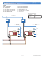
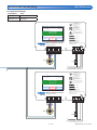
Two Zones with Commom Mixing
A671-5 Mechanical
400
V1
B1
423 & 346
444
B2
M1
S4
S5
S6
tN4 Mix 1 Bus
Description
The system has two snow melting zones heated by two boilers. The water temperature is regulated by a shared mixing valve
for the two snow melting zones. The boilers and mixing valve are operated by a Universal Reset Module 423, Power Manager
346 and Mixing Expansion Module 444. Each snow melting zone is operated by a WiFi Snow Melting Control 671.
• The slab target is determined by the melting/idling/storm setpoint and by the measured outdoor air temperature.
• The zone pump cycles on/off when heating the slab during melting/idling/storm operation.
• When the zone is heated, the 671 communicates to the 423 and 444 to operate the mixing valve and fire the boilers.
•
The 423 and 444 close the mixing valve to provide boiler return protection when the boiler supply temperature falls below
the 423 boiler minimum setting.
The system operation is dependent on sensor selection, as listed in the table below.
Sensor options Operation methods
Sensor
Sensor Model(s)
Auto Start/
Auto Stop
Auto Start/
Timed Stop
Manual Start/
Timed Stop
Slab Temperature
Control
S1 Automatic Snow/Ice Sensor 090 or 094 • – • •
S2 Aerial Snow Sensor 095 – • • –
S3 Slab Sensor 072 or 073 – – • •
S2+S3 Aerial Snow Sensor 095 and Slab Sensor 072/073 – • • •

© 2019 tekmar 671
_
A - 08/19
11 of 16
Two Zones with Commom Mixing A671-5 Mechanical
B1, B2 = Modulating Boilers
M1 = Actuator Motor 741
P1 = Zone 1 Pump
P2 = Zone 2 Pump
S1a = Zone 1 Snow/Ice Sensor 090 or 094
S1b = Zone 2 Snow/Ice Sensor 090 or 094
S2a = Zone 1 Snow Sensor 095
S2b = Zone 2 Snow Sensor 095
S3a = Zone 1 Slab Sensor 072 or 073
S3b = Zone 2 Slab Sensor 072 or 073
S4 = Outdoor Sensor 070
S5 = 423 Boiler Supply Sensor 082
S6 = 444 Mix Supply Sensor 082
V1 = 3-Way Mixing Valve 710 through 714
X1 = Transformer 009
Legend
400
S1a S1b
S2a
S2b
S3a
S3b
P1 P2
671 671
tN4 Mix 1 Bus
Zone #1 Zone #2
Zone #1
Snow/Ice Sensor Options
Zone #2
Snow/Ice Sensor Options
671 Application Settings
Setting Name Value
Boiler Type Control
Outdoor Sensor tekmarNet

12 of 16
© 2019 tekmar 671
_
A - 08/19
50
51 52 53
Stage1/ Stage 2/
Boil Enbl Setp Enbl
75
76 77 78
Demand Demand
DHW Setpoint
54 55
DHW Primary
10 A
max
79 80 81 82
N
Pump NPump
tN4
Made in Canada
8 VA 1 VA
Boil Sens Sup / Ret
H7010A
Off / DHW Sensor
Off / tekmar Stager
Boilers On-Off / Mod
Off / Rotation
Meets Class B: Canadian
ICES & FCC Part 15
Powered
Outputs
24 V (ac)
Universal Reset Module 423
Item
Menu
tektra 1006-01
Demands: 20 - 260 V (ac)
Relay Rating: 115 V (ac) 5 A
71
72 73 74
DHW 24 V (ac)
/
57 58 59 60 6156
C
C
tN4
Mod2 (dc)Mod1 (dc)
6564
C3
C1+–
C
+–
tN4
62 63
C2 tN4tN4
66 67
DHW
Com
Boiler
68 69
Boil Com
70
Out
Do not apply power
Test
1 2 3
Vlv R
No Power
Mixing Expansion Module 444
Variable Speed / Floating Action /
Modulating
Made in Canada
Signal wiring
must be rated at
least 300V / 90°C
Cut for mA output
5
R
6
R
41
tN4
7
Mod
+
8
Com
9
Mix
PowerClsOpn
Sys
Pmp
2
C
3
R
No Power
Date Code
1
tektra 1019-01
1
Power Manager 346
For product literature:
www.tekmarcontrols.com
Boiler Bus 0 Demand Power
Aux Pump 1
Aux Pump 2
Aux Pump 3
tN4
Bus 1 Demand
Bus 2 Demand
Bus 3 Demand
Meets Class B: Canadian
ICES & FCC Part 15
Caution! Disconnect All
Power before Opening
24 V (ac) Fuse: T2.5 A 250 V
H7011A
Relay Power
27 28
N
L
Aux Pump 2
29 30
N
Pmp
Aux Pump 3
31 32
N
Pmp
For product instructions, see brochure
Input Power: 115 V (ac) ±10% 60 Hz, 12 A
All Loads Using Input Power: 11.5 A
Relay Ratings: 115 V (ac) 5 A
Relay Power: 115 V (ac) ±10% 60 Hz, 10 A
Demands: 20 to 260 V (ac) 2 VA
Supply wires 90°C/105°C
See manual
Boil Bus
0
16 17
Demand
Bus
3Bus
2
18
Dem DemDem
19
Bus 1
20 21
Demand
227
tN4
56
t
N
4C C
2
Boil 0
11
tN4
910
2
CC
15
tN4
13 14
3
Com
Aux
Pmp1
4
RR R R
3
Aux
Pmp2
8
Aux
Pmp3
12
Limited power available, see wiring brochure
Room Occ
Room UnOcc
0Boil
1
2
3
1
3
11
9
7
5
12
10
8
6
4
2
Schedule
Member
Input Power
23 24
N
L
Aux Pump 1
25 26
N
Pmp
RC
Com
Open
Close
WiFi Snow Melting Control 671
Pulse Width Modulation
Power
Relays
1084-02
Designed and assembled in Canada
Date Code
H2058A
Blu
3
Yel
4
Brn/
5
Slab
Man
6
Melt
C
7
Blk/
2
Com
Red
1
BoilerHeat
Relay
System
Pump
11 12 13
Do Not Apply Power
Out
10
Com
9
tN4
8161514
Power
17
L
18
N
For product literature:
Pour la documentation du produit:
Para la literatura del producto:
tekmarControls.com
Disconnect all power before opening.
WARNING
Coupez l'alimentation avant l'ouverture.
ATTENTION
Desconecte la electricidad antes de abrir.
ADVERTENCIA
Signal wiring must be rated at least 300 V.
Le câblage du signal doit être d'une capacité d'au moins 300 V.
Cableado de señal debe tener una
calificación mínima de 300 V.
Contains WiFi transceiver:
FCC ID: Z64-CC3100M0DR1
Meets FCC Part 15B
IC: 4511-CC3100M0DR1
Meets CAN ICES-3 (B)/NMB-3(B)
115 V (ac) ±10%, 60 Hz, 20 VA
230 V (ac) 5 A 1/3 hp
This is a hole
Manual Melt
Time Left
- - : - - hrs
Outdoor
32 °F
Settings Status
System is Melting
Stop
10:30 AM
Warming Up
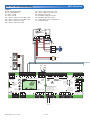
Two Zones with Commom Mixing
A671-6 Electrical
B1, B2 = Modulating Boilers
M1 = Actuator Motor 741
P1 = Zone 1 Pump
P2 = Zone 2 Pump
S1a = Zone 1 Snow/Ice Sensor 090 or 094
S1b = Zone 2 Snow/Ice Sensor 090 or 094
S2a = Zone 1 Snow Sensor 095
S2b = Zone 2 Snow Sensor 095
S3a = Zone 1 Slab Sensor 072 or 073
S3b = Zone 2 Slab Sensor 072 or 073
S4 = Outdoor Sensor 070
S5 = 423 Boiler Supply Sensor 082
S6 = 444 Mix Supply Sensor 082
V1 = 3-Way Mixing Valve 710 through 714
X1 = Transformer 009
Legend
S4S5
S6
B2
B1
L N
X1
M1
V1

© 2019 tekmar 671
_
A - 08/19
13 of 16
50
51 52 53
Stage1/ Stage 2/
Boil Enbl Setp Enbl
75
76 77 78
Demand Demand
DHW Setpoint
54 55
DHW Primary
10 A
max
79 80 81 82
N
Pump NPump
tN4
Made in Canada
8 VA 1 VA
Boil Sens Sup / Ret
H7010A
Off / DHW Sensor
Off / tekmar Stager
Boilers On-Off / Mod
Off / Rotation
Meets Class B: Canadian
ICES & FCC Part 15
Powered
Outputs
24 V (ac)
Universal Reset Module 423
Item
Menu
tektra 1006-01
Demands: 20 - 260 V (ac)
Relay Rating: 115 V (ac) 5 A
71
72 73 74
DHW 24 V (ac)
/
57 58 59 60 6156
C
C
tN4
Mod2 (dc)Mod1 (dc)
6564
C3
C1+–
C
+–
tN4
62 63
C2 tN4tN4
66 67
DHW
Com
Boiler
68 69
Boil Com
70
Out
Do not apply power
Test
1 2 3
Vlv R
No Power
Mixing Expansion Module 444
Variable Speed / Floating Action /
Modulating
Made in Canada
Signal wiring
must be rated at
least 300V / 90°C
Cut for mA output
5
R
6
R
41
tN4
7
Mod
+
8
Com
9
Mix
PowerClsOpn
Sys
Pmp
2
C
3
R
No Power
Date Code
1
tektra 1019-01
1
Power Manager 346
For product literature:
www.tekmarcontrols.com
Boiler Bus 0 Demand Power
Aux Pump 1
Aux Pump 2
Aux Pump 3
tN4
Bus 1 Demand
Bus 2 Demand
Bus 3 Demand
Meets Class B: Canadian
ICES & FCC Part 15
Caution! Disconnect All
Power before Opening
24 V (ac) Fuse: T2.5 A 250 V
H7011A
Relay Power
27 28
N
L
Aux Pump 2
29 30
N
Pmp
Aux Pump 3
31 32
N
Pmp
For product instructions, see brochure
Input Power: 115 V (ac) ±10% 60 Hz, 12 A
All Loads Using Input Power: 11.5 A
Relay Ratings: 115 V (ac) 5 A
Relay Power: 115 V (ac) ±10% 60 Hz, 10 A
Demands: 20 to 260 V (ac) 2 VA
Supply wires 90°C/105°C
See manual
Boil Bus
0
16 17
Demand
Bus
3Bus
2
18
Dem DemDem
19
Bus 1
20 21
Demand
227
tN4
56
t
N
4C C
2
Boil 0
11
tN4
910
2
CC
15
tN4
13 14
3
Com
Aux
Pmp1
4
RR R R
3
Aux
Pmp2
8
Aux
Pmp3
12
Limited power available, see wiring brochure
Room Occ
Room UnOcc
0Boil
1
2
3
1
3
11
9
7
5
12
10
8
6
4
2
Schedule
Member
Input Power
23 24
N
L
Aux Pump 1
25 26
N
Pmp
RC
Com
Open
Close
WiFi Snow Melting Control 671
Pulse Width Modulation
Power
Relays
1084-02
Designed and assembled in Canada
Date Code
H2058A
Blu
3
Yel
4
Brn/
5
Slab
Man
6
Melt
C
7
Blk/
2
Com
Red
1
BoilerHeat
Relay
System
Pump
11 12 13
Do Not Apply Power
Out
10
Com
9
tN4
8161514
Power
17
L
18
N
For product literature:
Pour la documentation du produit:
Para la literatura del producto:
tekmarControls.com
Disconnect all power before opening.
WARNING
Coupez l'alimentation avant l'ouverture.
ATTENTION
Desconecte la electricidad antes de abrir.
ADVERTENCIA
Signal wiring must be rated at least 300 V.
Le câblage du signal doit être d'une capacité d'au moins 300 V.
Cableado de señal debe tener una
calificación mínima de 300 V.
Contains WiFi transceiver:
FCC ID: Z64-CC3100M0DR1
Meets FCC Part 15B
IC: 4511-CC3100M0DR1
Meets CAN ICES-3 (B)/NMB-3(B)
115 V (ac) ±10%, 60 Hz, 20 VA
230 V (ac) 5 A 1/3 hp
This is a hole
Manual Melt
Time Left
- - : - - hrs
Outdoor
32 °F
Settings Status
System is Melting
Stop
10:30 AM
Warming Up
WiFi Snow Melting Control 671
Pulse Width Modulation
Power
Relays
1084-02
Designed and assembled in Canada
Date Code
H2058A
Blu
3
Yel
4
Brn/
5
Slab
Man
6
Melt
C
7
Blk/
2
Com
Red
1
BoilerHeat
Relay
System
Pump
11 12 13
Do Not Apply Power
Out
10
Com
9
tN4
8161514
Power
17
L
18
N
For product literature:
Pour la documentation du produit:
Para la literatura del producto:
tekmarControls.com
Disconnect all power before opening.
WARNING
Coupez l'alimentation avant l'ouverture.
ATTENTION
Desconecte la electricidad antes de abrir.
ADVERTENCIA
Signal wiring must be rated at least 300 V.
Le câblage du signal doit être d'une capacité d'au moins 300 V.
Cableado de señal debe tener una
calificación mínima de 300 V.
Contains WiFi transceiver:
FCC ID: Z64-CC3100M0DR1
Meets FCC Part 15B
IC: 4511-CC3100M0DR1
Meets CAN ICES-3 (B)/NMB-3(B)
115 V (ac) ±10%, 60 Hz, 20 VA
230 V (ac) 5 A 1/3 hp
This is a hole
Manual Melt
Time Left
- - : - - hrs
Outdoor
32 °F
Settings Status
System is Melting
Stop
10:30 AM
Warming Up
Two Zones with Commom Mixing
A671-6 Electrical
S1a
S1b
P1
P2
L
L
N
N
671 Application Settings
Setting Name Value
Boiler Type Control
Outdoor Sensor tekmarNet

14 of 16
© 2019 tekmar 671
_
A - 08/19
Page left intentionally blank.

© 2019 tekmar 671
_
A - 08/19
15 of 16
Page left intentionally blank.

671
_
A - 08/19 16 of 16 © 2019 tekmar
Tel: 1-800-438-3903 • Fax: (250) 984-0815
tekmarControls.com
All specications are subject to change without notice
Specifications
The following are the recommended specifications for the WiFi Snow Melting Control 671.
• The control shall have the ability to use a snow/ice sensor in order to automatically detect snow or ice and begin operation
of the system. The system shall continue to run until the sensor is dry or the control is manually stopped.
• The control shall have the ability to be manually started with an adjustable running time that counts down and automatically
stops the system.
•
The control shall not operate the system to provide heat to the snow melting zones when it enters into either a Warm Weather
Shut Down (WWSD) or a Cold Weather Cut Off (CWCO) mode.
• The system water temperature shall be based on the outdoor temperature and feedback from sensors located in the snow
melting slabs.
• The control shall have two separate access levels to limit the number of adjustments available to various users.
• The control shall have a manual override that allows each output to be manually turned on or off.
•
The control shall continuously monitor its temperature sensors and provide an error message upon a control or sensor failure.
•
The control shall record and display boiler and pump running hours and minimum and maximum temperatures depending
on the access level that has been selected.
•
During extended periods of inactivity, the pumps that are operated by the control shall be periodically exercised to prevent
seizure during long idle periods.
This Application Brochure is not intended to provide full installation instructions and safety information. In order to avoid property
damage or injury, please refer to the complete installation manual and product safety information provided with the product.
-
 1
1
-
 2
2
-
 3
3
-
 4
4
-
 5
5
-
 6
6
-
 7
7
-
 8
8
-
 9
9
-
 10
10
-
 11
11
-
 12
12
-
 13
13
-
 14
14
-
 15
15
-
 16
16


Watts WiFi Snow Melting Control 671_A Guide d'installation
- Taper
- Guide d'installation
- Ce manuel convient également à
dans d''autres langues
Documents connexes
-
Watts Snow Melting Control 654 Guide d'installation rapide
-
Watts Thermostat 518 Guide d'installation rapide
-
Watts Radiant Thermostat 519 Guide d'installation
-
Watts 402 Guide d'installation rapide
-
Watts 4 Thermostat 538 Guide d'installation rapide
-
-
Watts Thermostat 553 Guide d'installation rapide
-
Watts Thermostat 532 Guide d'installation rapide
-
-