
1
Indoor/Outdoor
1A2, 3A2, 3S, 3T, 8A2

2
Congratulations on your purchase of
J
amo Indoor/Outdoor speakers.
P
ackage content.
Speaker (2) Port plug “i” (4) Allen wrench (1)
Assembled bracket (2) Thumb screw “j” (4) Manual (1)
Screw plug “g” (8) Covers “k” (4)
B
racket.
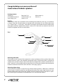
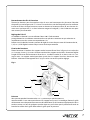
The brackets comes pre-assembled. If disassembling the bracket for paint-
ing, re-assemble it as follow: Place the curved bracket (a) between the wall
bracket (b) and wall bracket cover (c) as shown in fig. 1. Insert two 1” allen
bolts (d) through wall bracket into wall bracket cover and tighten with the
supplied allen wrench. Insert two ½” allen bolts (e) into each side of wall
bracket and tighten towards curved bracket.
M
ounting of bracket.
The bracket can be mounted for horizontal or vertical placement of the
speaker. Mount the bracket with four screws (not included) appropriate for
the surface the bracket is mounted to (wood, brick, concrete or other). Take
into account the weight of the speaker (specications on back). A hole (f) in
the middle of the bracket allows for running the speaker wire through the
bracket if so desired. Cover the screws with four screw plugs (g) fig. 2.
M
ounting of port plugs.
If the front of the speaker is exposed to rain directly entering the bass reex
ports (under the grill), the ports should be closed to avoid lling the
speaker with water. High moisture is not a problem. Remove the grill (h)
from the speaker and insert two port plugs (i) into the bass ports. Re-install
the grill. The speaker will reproduce less bass with the ports closed.
Fig. 1
b
c
d
e
a
d
e
f
Congratulations on your purchase of
Jamo Indoor/Outdoor speakers
Package content
Speaker (2) Port plug “i” (4) Allen wrench (1)
Assembled bracket (2) Thumb screw “j” (4) Manual (1)
Screw plug “g” (8) Covers “k” (4)
Bracket
The brackets comes pre-assembled. If disassembling the bracket for paint-ing, re-assemble it
as follow: Place the curved bracket (a) between the wall bracket (b) and wall bracket cover
(c) as shown in g. 1. Insert two 1” allen bolts (d) through wall bracket into wall bracket cover
and tighten with the supplied allen wrench. Insert two ½” allen bolts (e) into each side of wall
bracket and tighten towards curved bracket.
Mounting of bracket
The bracket can be mounted for horizontal or vertical placement of the speaker. Mount the
bracket with four screws (not included) appropriate for the surface the bracket is mounted to
(wood, brick, concrete or other). Take into account the weight of the speaker (specications on
back). A hole (f ) in the middle of the bracket allows for running the speaker wire through the
bracket if so desired. Cover the screws with four screw plugs (g) g. 2.
Mounting of port plugs
If the front of the speaker is exposed to rain directly entering the bass reex ports (under the
grill), the ports should be closed to avoid lling the speaker with water. High moisture is not a
problem. Remove the grill (h) from the speaker and insert two port plugs (i) into the bass ports.
Re-install the grill. The speaker will reproduce less bass with the ports closed.
Fig. 1

3
k
k
j
j
h
i
i
g
g
l
Connecting speaker wires
Loosen speaker terminals by turning counter clockwise. Strip ½”/12 mm in-sulation o each
wire. Twist strands on each wire to form “solid” wire.
Insert one wire into each terminal and tighten terminal by turning clockwise. Make sure posi-
tive (+) is to red terminal and negative (-) to black terminal for correct phasing.
Adjustment of I/O 3T
This model is for 70V or 100V line installation. This is mainly used in com-mercial installations
with many speakers and requires an amplier with matching transformer outputs. A switch
located next to the terminals al-lows for adjustments of the level of the speaker in 10W, 5W,
2.5W and 1.25W settings. Adjust the switch to the desired level on each speaker.
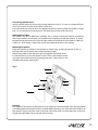
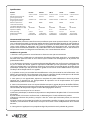
Mounting of speaker
Place the speaker inside the curved bracket as shown in g. 2 and insert thumb screws (j)
through each end of the curved bracket into the speaker.
Adjust the speaker to the desired angle and tighten the thumb screws.
In-stall the covers (k) over the thumb screws. The curved bracket can be
ad-justed in the wall bracket by loosening the two ½” allen bolts (e) and
re-tighten them after adjustment.
Fig. 2
Painting
The speaker and bracket can be painted. Spray painting is recommended. Paint all parts before
assembling. Remove the grill from the speaker before painting and cover the front bae (l) of
the speaker. Apply many thin coats instead of a few thick coats to avoid the paint running or
clogging the grill holes. Re-install grill after painting.

4
Model I/O 1A2 I/O 3A2
I/O 3S
I/O 3T I/O 8A2
System 2 way ported 2 way ported
2 way ported
2 way ported 2 way ported
Woofer (in/mm) 4½/114 5¼/133
5¼/133
5¼/133 8/203
Tweeter (in/mm) ½/13 Dome 1/25 Dome
2x1/25 Dome
1/25 Dome 1/25 Dome
Power (W long/short term) 20/40 40/80
40/80
40/80 80/125
Sensitivity (dB/2.83V/1m) 86 88
88
88 88
Frequency range (Hz) 77-20.000 64-20.000
55-20 000
64-20.000 50-20.000
Impedance (Ohm) 6 8
8 + 8
70/100V line 8
Weight (lb/kg) 5.1/2.3 6.9/3.2
8.3/3.8
7.3/3.3 10.1/4.6
Dimensions HxWxD (in/mm)
9.1x6.3x6.6 11.4x7.9x8.2
11.4x7.9x8.2
11.4x7.9x8.2 13.5x9.3x9.8
232x160x168 290x200x209 290x200x209 290x200x209 344x237x248
The scope of the warranty
Service. In case of warranty enquiries, please contact your dealer/installer. In case of request for
service under warranty, please enclose your original receipt and make sure that the serial number
on the product is readable. Important: Never send the product to be repaired without the prior
agreement of your dealer. The product must always be packed properly. If the product is NOT UNDER
WARRANTY, all costs including without limit costs of repair and freight must be paid for by the
customer.
Terms of Warranty
1. Nothing in this warranty shall limit your statutory rights.
2. The warranty is only valid on presentation of the original sales receipt or other valid proof of
purchase, and provided that the serial number on the product is fully legible.
3. Warranty repairs must be carried out by an authorised Jamo dealer, or an authorised service centre.
No payment will be made for repairs performed by unauthorised persons. This warranty does not
extend to products which have been repaired or otherwise altered by unauthorised persons, and
any damage to the product caused by work by unauthorised persons is not covered by this warranty.
4. This product will not be considered defective, either in materials or in manufacture, to the extent
that faults are caused by adaptation to national, local, technical or safety related requirements in
countries other than the specific country where the product was purchased.
5. Jamo shall at its option during the relevant warranty period either repair or replace defective
components. If the component repair or replacement cannot be performed, the product will be
replaced.
6. In no circumstances shall Jamo be liable in contract, tort (including negligence) or breach of
statutory duty or otherwise for loss of profits, loss of revenue, loss of data, loss of business or loss of
anticipated savings or for any consequential loss whatever.
7. The warranty does not cover the following:
a) Periodic inspection, maintenance and repair or replacement of parts resulting from normal wear
and tear.
b) Costs connected to delivery to the dealer, disassembly or re-installation of the product.
c) Misuse, including use for purposes other than was intended, or faulty installation.
d) Damage caused by lightning, water, fire, natural catastrophes, war, insurrection, incorrect line
voltage, insufficient ventilation, transport or other causes outside of the control of Jamo.
8. This warranty applies to every legal owner of the product during the warranty period.
Specications

Enceintes à usage intérieur et extérieur
1A2, 3A2, 3S, 3T, 8A2

6
Congratulations on your purchase of
J
amo Indoor/Outdoor speakers.
P
ackage content.
Speaker (2) Port plug “i” (4) Allen wrench (1)
Assembled bracket (2) Thumb screw “j” (4) Manual (1)
Screw plug “g” (8) Covers “k” (4)
B
racket.
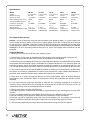
The brackets comes pre-assembled. If disassembling the bracket for paint-
ing, re-assemble it as follow: Place the curved bracket (a) between the wall
bracket (b) and wall bracket cover (c) as shown in fig. 1. Insert two 1” allen
bolts (d) through wall bracket into wall bracket cover and tighten with the
supplied allen wrench. Insert two ½” allen bolts (e) into each side of wall
bracket and tighten towards curved bracket.
M
ounting of bracket.
The bracket can be mounted for horizontal or vertical placement of the
speaker. Mount the bracket with four screws (not included) appropriate for
the surface the bracket is mounted to (wood, brick, concrete or other). Take
into account the weight of the speaker (specications on back). A hole (f) in
the middle of the bracket allows for running the speaker wire through the
bracket if so desired. Cover the screws with four screw plugs (g) fig. 2.
M
ounting of port plugs.
If the front of the speaker is exposed to rain directly entering the bass reex
ports (under the grill), the ports should be closed to avoid lling the
speaker with water. High moisture is not a problem. Remove the grill (h)
from the speaker and insert two port plugs (i) into the bass ports. Re-install
the grill. The speaker will reproduce less bass with the ports closed.
Fig. 1
b
c
d
e
a
d
e
f
Toutes nos félicitations pour avoir acheté ces
enceintes Jamo pour usage intérieur et extérieur
Contenu de l’emballage
Enceintes (2) Porte-prises “i” (4) Clé hexagonale (1)
Support assemblé (2) Vis à serrage “j” (4) Manuel (1)
Cache vis “g” (8) Cache “k” (4)
Support
Le support est livré pré-assemblé. Si le support est démonté pour être peint, il faut le réassem-
bler en suivant cette procédure : placez le support courbé (a) entre les supports muraux (b) et le
cache support (c) comme montré dans la gure. 1. Insérez deux boulons à tête creuse hexago-
nale de 1 pouce (d) à travers le support mural, dans le cache du support mural et serrez avec la
clé hexagonale. Insérez deux boulons à tête creuse hexagonale de ½ pouce (e) de chaque côté
du support mural, et serrez pour xer le support courbé.
Fixation du support
Le support peut être xé de manière à y placer une enceinte à l’horizontale ou à la verticale.
Utilisez quatre vis (non incluses) appropriées à la surface à laquelle le support est xé (bois,
brique, béton ou autre). Il faut tenir compte du poids de l’enceinte (spécications au dos). Le
trou (f) au milieu du
support permet de faire passer les ls de l’enceinte si c’est nécessaire.
Couvrez les vis à l’aide de quatre caches vis (g) g. 2.
Fixation du porte-prises
Si l’avant de l’enceinte est exposé directement à la pluie menant aux évents de résonance
(sous la grille), les ports doivent être bouchés pour éviter l’inondation des haut-parleurs. Une
grande humidité est sans eet. Retirez la grille (h) de l’enceinte et insérez deux porte-prises (i)
les évents des graves. Remettez la grille. L’enceinte émettra moins de graves si les ports sont
fermés.
Fig. 1

7
k
k
j
j
h
i
i
g
g
l
Raccordement des ls de l’enceinte
Tournez les borniers pour haut-parleurs dans le sens anti-horaire pour les desserrer. Dénudez
chaque l sur une longueur de ½”/12 mm. Tressez les brins des de chaque l pour les renforcer.
Insérez un l dans chaque bornier et serrez ce dernier en le tournant dans le sens horaire. As-
surez-vous que le positif (+) va dans le bornier rouge et le négatif (-) dans le bornier noir pour
une mise en phase correcte.
Réglage de l’I/O 3T
Ce modèle est destiné à une installation 70 ou 100 V. Cela concerne
principalement les installations commerciales avec plusieurs enceintes et qui nécessite un
amplicateur avec des sorties correspondantes. Un
bouton situé à côté des borniers permet de régler le niveau de puissance de l’enceinte de 10,
5, 2,5 ou 1,25 W. Rglez le niveau de puissance de chaque enceinte.
Fixation de l’enceinte
Placez l’enceinte à l’intérieur du support courbé comme illustré dans la gure. 2 et insérez des
vis à serrage à main (j) à travers chaque extrémité du support courbé dans l’enceinte. Réglez
l’angle d’inclinaison de l’enceinte et serrez les vis. Installez le cache (k) au dessus des vis à ser-
rage à main. Le support courbé peut être ajusté dans le support mural en desserrant deux
boulons à tête creuse hexagonale de ½” (e) puis en les resserrant après le réglage.
Fig. 2
Peinture
Vous pouvez peindre l’enceinte et les vis. La peinture par pulvérisation est
recommandée. Il vaut mieux peindre tous les composants avant l’assemblage. Retirez la grille
de l’enceinte avant de peindre en couvrant le bae frontal (l) de l’enceinte. Appliquez plusieurs
couches minces au lieu de quelques couches épaisses pour éviter que la peinture ne coule et
bouche les orices de la grille. Réinstallez la grille après la peinture.

8
Specications
Couverture de la garantie
Service. Veuillez contacter votre fournisseur/installateur pour toute question relative à la garantie. Si
vous souhaitez faire appel à la garantie, veuillez joindre à votre demande l’original de votre récépissé
et vous assurer que le numéro de série figurant sur le produit soit bien lisible. Important: N’envoyez
jamais votre produit en réparation sans l’accord préalable de votre fournisseur. Le produit doit
toujours être correctement emballé. Si le produit N’EST PAS SOUS GARANTIE, tous les frais d’envoi et
de réparation seront à la charge du consommateur, sans aucune limite de somme.
Conditions de garantie
1. Rien dans cette garantie ne saurait limiter vos droits en tant que consommateur.
2. La garantie n’est valable que sur présentation du récépissé de vente original ou sur présentation
de toute autre preuve d’achat et sous réserve que le numéro de série figurant sur le produit soit
parfaitement lisible.
3. Les réparations couvertes par la garantie doivent être effectuées par un fournisseur agréé de Jamo
ou par un centre de service agréé. Les réparations effectuées par des personnes non agréées ne
seront pas remboursées. La garantie ne s’étend pas aux produits qui ont été réparés ou altérés d’une
quelconque manière par des personnes non agréées et ne couvre aucune détérioration du produit
causée par le fait de personnes non agréées.
4. Ce produit ne sera pas considéré comme défectueux sur le plan matériel ou de la fabrication si les
défauts sont consécutifs à leur adaptation à des normes nationales, locales, techniques ou de sécurité
en vigueur dans des pays autres que celui où le produit a été vendu.
5. Jamo pourra, à son appréciation, réparer ou remplacer les pièces défectueuses durant la période
couverte par la garantie. En cas d’impossibilité de réparation ou de remplacement de la pièce
défectueuse, le produit sera échangé.
6. Jamo ne saurait être en aucun cas responsable des manques à gagner, des pertes de chiffre d’affaires,
de données, d’épargne ou de toute autre préjudice indirect découlant d’une violation des stipulations
contractuelles, des dispositions légales ou d’un délit (négligences incluses).
7. La garantie ne couvre pas les cas suivants :
a) Révisions périodiques, maintenance, réparation ou remplacement de pièces liées à l’usure normale
du produit.
b) Coûts relatifs à la livraison au fournisseur, au démontage ou à la réinstallation du produit.
c) Mauvaise utilisation du produit, y compris à des fins autres que l’utilisation prévue, ou mauvaise
installation.
d) Dégâts causés par la lumière, l’eau, le feu, les catastrophes naturelles, la guerre, une insurrection, une
surtension, une ventilation insuffisante, le transport ou d’autres causes indépendantes de la volonté
de Jamo.
8. Cette garantie s’applique à tout propriétaire légal du produit durant la période de garantie.
Modèle I/O 1A2 I/O 3A2 I/O 3S I/O 3T I/O 8A2
Système 2 voies à évent 2 voies à évent 2 voies à évent 2 voies à évent 2 voies à évent
Woofer (haut-parleur de
graves) (pouce/mm)
4½/114 5¼/133 5¼/133 5¼/133 8/203
Tweeter (haut-parleurs
d'aigus) (pouce/mm)
à dôme ½/13 à dôme 1/25 à dôme 2x1/25 à dôme 1/25 à dôme 1/25
Puissance (Puissance
continue/instantanée)
20/40 40/80 40/80 40/80 80/125
Sensibilité (dB/2,83 V/1 m) 86 88 88 88 88
Gamme de fréquences (Hz) 77-20 000 64-20 000 55-20 000 64-20 000 50-20 000
Impédance (Ohm) 6 8 8 + 8 70/100 V line 8
Poids (livre/kg) 5,1/2,3 6,9/3,2 8,3/3,8 7,3/3,3 10,1x4,6
Dimensions (HxLxP)
(pouce/mm)
9,1x6,3x6,6
232x160x168
11,4x7,9x8,2
232x160x168
11,4x7,9x8,2
290x200x209
11,4x7,9x8,2
290x200x209
13,5x9,3x9,8
344x237x248

9
-
 1
1
-
 2
2
-
 3
3
-
 4
4
-
 5
5
-
 6
6
-
 7
7
-
 8
8
-
 9
9


dans d''autres langues
- English: Jamo 3A2 User manual
Documents connexes
Autres documents
-
Optimus COS-3100VA Manuel utilisateur
-
Polk Audio ATRIUM 60 Manuel utilisateur
-
Klipsch CP-6t-BL Le manuel du propriétaire
-
Klipsch CP-4 Le manuel du propriétaire
-
-
 MartinLogan Stage X Manuel utilisateur
-
 Musica 52WRM Manuel utilisateur
-
Klipsch CP-T Manuel utilisateur

