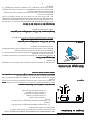
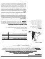
Frigidaire PLHV36W6KC Manuel utilisateur
- Catégorie
- Hottes
- Taper
- Manuel utilisateur

OWNER’S GUIDE
PLHV36W6KC
READ AND SAVE THESE INSTRUCTIONS
Contents
Product Registration....................................................................................2
Important Safety Instructions .....................................................................3
Installation ................................................................................................4-7
Use and Care ................................................................................................8
Hood Cleaning .............................................................................................8
Lights Replacement ..................................................................................... 9
Warranty..................................................................................................... 12
Range Hood
P/N 316 137 202
LI1NSA

2
Product RegistrationProduct Registration
Product RegistrationProduct Registration
Product Registration
Register your ProductRegister your Product
Register your ProductRegister your Product
Register your Product
The self-addressed
PRODUCTPRODUCT
PRODUCTPRODUCT
PRODUCT
REGISTRATION CARDREGISTRATION CARD
REGISTRATION CARDREGISTRATION CARD
REGISTRATION CARD should be
filled in completely, signed and
returned to the Frigidaire Canada.
This Owner’s Guide contains general
operating instructions for your range
hood and feature information for
several models. Your range hood
may not may not
may not may not
may not have all the described
features.
Note:Note:
Note:Note:
Note: The instructions appearing in
this Owner’s Guide are not meant to
cover every possible condition and
situation that may occur. Common
sense and caution must be practiced
when installing, operating and
maintaining any appliance.
Thank you for choosing this appliance. Thank you for choosing this appliance.
Thank you for choosing this appliance. Thank you for choosing this appliance.
Thank you for choosing this appliance. The information contained within
this Owner’s Guide will instruct you on how to properly operate and care for
your range hood. Please read through the information contained in your
literature pack to learn more about your new appliance.
Record Your Model and Serial Numbers
Record in the space provided below the model and serial numbers found on
the serial plate located on the right hand side of the range hood.
Model Number:Model Number:
Model Number:Model Number:
Model Number:
______________________________________________________________________________________________________
______________________________________________________________________________________________________
___________________________________________________
Serial Number:Serial Number:
Serial Number:Serial Number:
Serial Number:
______________________________________________________________________________________________________
______________________________________________________________________________________________________
___________________________________________________
Date of Purchase:Date of Purchase:
Date of Purchase:Date of Purchase:
Date of Purchase:
__________________________________________________________________________________________________
__________________________________________________________________________________________________
_________________________________________________

3
Important Safety InstructionsImportant Safety Instructions
Important Safety InstructionsImportant Safety Instructions
Important Safety Instructions
READ AND SAREAD AND SA
READ AND SAREAD AND SA
READ AND SA
VE THESE INSTRUCTIONSVE THESE INSTRUCTIONS
VE THESE INSTRUCTIONSVE THESE INSTRUCTIONS
VE THESE INSTRUCTIONS
TT
TT
T
ake care when using cleaning agents or detergents.ake care when using cleaning agents or detergents.
ake care when using cleaning agents or detergents.ake care when using cleaning agents or detergents.
ake care when using cleaning agents or detergents.
Suitable for use in household cooking areaSuitable for use in household cooking area
Suitable for use in household cooking areaSuitable for use in household cooking area
Suitable for use in household cooking area
CAUTIONCAUTION
CAUTIONCAUTION
CAUTION - To reduce risk of fire and to properly exhaust air, be sure to duct air outside – Do not vent exhaust
air into spaces within walls or ceilings or into attics, crawl spaces, or garages.
CAUTIONCAUTION
CAUTIONCAUTION
CAUTION - For General Ventilating Use Only. Do Not Use To Exhaust Hazardous Or Explosive Materials And
Vapors.
WARNINGWARNING
WARNINGWARNING
WARNING – TO REDUCE THE RISK OF FIRE, ELECTRIC SHOCK, OR INJURY TO PERSONS, OBSERVE THE
FOLLOWING:
a. Use this unit only in the manner intended by the manufacturer. If you have questions, contact the
manufacturer.
b. Before servicing or cleaning unit, switch power off at service panel and lock the service disconnecting means
to prevent power from being switched on accidentally. When the service disconnecting means cannot be
locked, securely fasten a prominent warning device, such as a tag, to the service panel.
WARNINGWARNING
WARNINGWARNING
WARNING – TO REDUCE THE RISK OF A RANGE TOP GREASE FIRE:
a. Never leave surface units unattended at high settings. Boilovers cause smoking and greasy spillovers that may
ignite. Heat oils slowly on low or medium settings.
b. Always turn hood ON when cooking at high heat or when cooking flaming foods.
c. Clean ventilating fans frequently. Grease should not be allowed to accumulate on fan or filter.
d. Use proper pan size. Always use cookware appropriate for the size of the surface element.
WARNINGWARNING
WARNINGWARNING
WARNING – TO REDUCE THE RISK OF INJURY TO PERSONS IN THE EVENT OF A RANGE TOP GREASE FIRE,
OBSERVE THE FOLLOWING:
a. SMOTHER FLAMES with a close-fitting lid, cookie sheet, or metal tray, then turn off the burner. BE CAREFUL
TO PREVENT BURNS. If the flames do not go out immediately, EVACUATE AND CALL THE FIRE DEPARTMENT.
b. NEVER PICK UP A FLAMING PAN – You may be burned.
c. DO NOT USE WATER, including wet dishcloths or towels – a violent steam explosion will result.
d. Use an extinguisher ONLY if:
1. You know you have a Class ABC extinguisher, and you already know how to operate it.
2. The fire is small and contained in the area where it started.
3. The fire department is being called.
4. You can fight the fire with your back to an exit.
WARNINGWARNING
WARNINGWARNING
WARNING – TO REDUCE THE RISK OF FIRE, ELECTRIC SHOCK, OR INJURY TO PERSONS, OBSERVE THE
FOLLOWING:
a) Installation work and electrical wiring must be done by qualified person(s) in accordance with all applicable
codes and standards, including fire-rated construction.
b) Sufficient air is needed for proper combustion and exhausting of gases through the flue (chimney) of fuel
burning equipment to prevent back drafting. Follow the heating equipment manufacturer’s guideline and
safety standards such as those published by the National Fire Protection Association (NFPA), and the American
Society for Heating, Refrigeration and Air Conditioning Engineers (ASHRAE), and the local code authorities.
c) When cutting or drilling into wall or ceiling, do not damage electrical wiring and other hidden utilities.
d) Ducted fans must always be vented to the outdoors.
WARNINGWARNING
WARNINGWARNING
WARNING - TO REDUCE THE RISK OF FIRE, USE ONLY METAL DUCTWORK.
WARNING
Electrical Shock HazardElectrical Shock Hazard
Electrical Shock HazardElectrical Shock Hazard
Electrical Shock Hazard - Can result in serious injury or death.
Disconnect appliance from electric power before servicing.
If equipped, the fluorescent light bulb contains small amounts of mercury which
must be recycled or disposed of according to Local, State, and Federal Codes.

4
InstallationInstallation
InstallationInstallation
Installation
FOR RESIDENTIAL USE ONLYFOR RESIDENTIAL USE ONLY
FOR RESIDENTIAL USE ONLYFOR RESIDENTIAL USE ONLY
FOR RESIDENTIAL USE ONLY
NOT TO BE INSTALLED OVER GAS GRILLSNOT TO BE INSTALLED OVER GAS GRILLS
NOT TO BE INSTALLED OVER GAS GRILLSNOT TO BE INSTALLED OVER GAS GRILLS
NOT TO BE INSTALLED OVER GAS GRILLS
PLEASE READ ENTIRE INSTRUCTIONS BEFORE PROCEEDING.PLEASE READ ENTIRE INSTRUCTIONS BEFORE PROCEEDING.
PLEASE READ ENTIRE INSTRUCTIONS BEFORE PROCEEDING.PLEASE READ ENTIRE INSTRUCTIONS BEFORE PROCEEDING.
PLEASE READ ENTIRE INSTRUCTIONS BEFORE PROCEEDING.
INSTALLATION MUST COMPLY WITH ALL LOCAL CODES.INSTALLATION MUST COMPLY WITH ALL LOCAL CODES.
INSTALLATION MUST COMPLY WITH ALL LOCAL CODES.INSTALLATION MUST COMPLY WITH ALL LOCAL CODES.
INSTALLATION MUST COMPLY WITH ALL LOCAL CODES.
IMPORTANT:IMPORTANT:
IMPORTANT:IMPORTANT:
IMPORTANT: Save these Instructions for the Local Electrical Inspector’s use.
INSTALLER:INSTALLER:
INSTALLER:INSTALLER:
INSTALLER: Please leave these Instructions with this unit for the owner.
OWNER:OWNER:
OWNER:OWNER:
OWNER: Please retain these instructions for future reference.
Safety Warning: Turn off power circuit at the service entrance and lock out
panel, before wiring this appliance.
Requirement: 120 V AC, 60 Hz. 15 or 20 A
Weight: 42 lbs
Diameter of Transition: 6”
Diameter of exhaust Duct required: 6”
DimensionsDimensions
DimensionsDimensions
Dimensions
Considerations before installing HoodConsiderations before installing Hood
Considerations before installing HoodConsiderations before installing Hood
Considerations before installing Hood
1. For the most efficient air flow exhaust, use a straight run or as few elbows
as possible.
CAUTION:CAUTION:
CAUTION:CAUTION:
CAUTION: Vent unit to outside of building, only.
2. If allowed in your area, use metallic flex ducting only to connect rigid duct
directly to transitions.
3. COLD WEATHER installations should have an additional backdraft damper
installed to minimize backward cold air flow and a nonmetallic thermal
break to minimize conduction of outside temperatures as part of the
ductwork. The damper should be on the cold air side of the thermal break.
The break should be as close as possible to where the ducting enters the
heated portion of the house.
4. Hood installation height above cooktop is the users preference. The lower
the hood above the cooktop, the more efficient the capturing of cooking
odors, grease and smoke. We recommends the hood be installed 30-36"
above the countertop. The lower height may be inconvenient for tall
people and large cooking vessels. Check your ceiling height and the hood
height maximum before you select your hood.
Figure 1*Figure 1*
Figure 1*Figure 1*
Figure 1*
Note: All dimensions are
shown in inches.
* Dimensions are given from
base of hood to ceiling, and
include clearance required
for installation.
Dimensions
A (Range of adjustable ht.)* 33
7
/
16
- 42
3
/
8
B (Min. ht. with one cover)* 26
W (widht) x D (depth) 8
3
/
16
x 6
7
/
8
AA (Cover adjustable ht.) 23
7
/
16
- 32
15
/
16
BB (Cover min. height) 16

5
InstallationInstallation
InstallationInstallation
Installation
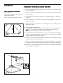
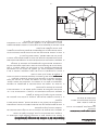
Preparation of mounting surface (Drywall)Preparation of mounting surface (Drywall)
Preparation of mounting surface (Drywall)Preparation of mounting surface (Drywall)
Preparation of mounting surface (Drywall)
1. Select a mounting height comfortable for the user and mark on wall
behind cooktop.
2. Mark center line of cooktop and draw vertical line from bottom of hood
to the ceiling.
3. Tape template, matching center-line and hood bottom as shown in
Figure 2.
4. Mark centers of the 6 fastener locations through template on wall then
remove template.
5. Mark wall with horizontal line 1" above highest and 1" below lowest
fastener location.
6. Find studs behind drywall by
tapping wall or using a stud finder. Mark the center of the studs with a
vertical line to the right and left of the marked fastener location.
NoteNote
NoteNote
Note: 2 x 6's must span at least 2 studs side to side.
7. Cutout drywall along marked lines. Install 2 x 6's between studs firmly
flush with stud front. Make sure all mounting screws will anchor to added
lumber. Replace drywall and refinish.
8. Remark center line and hood bottom on same location as before and tape
template on wall as in step 3 above.
9. Mount 2 mounting hooks with wood screws (supplied in mounting
hardware kit) on locationsmarked on template, then remove template.
10. Install duct cover ceiling bracket to wall flush to ceiling with drywall
anchors supplied. Figure 3.
Figure 2Figure 2
Figure 2Figure 2
Figure 2
C
L
16
16
Figure 3Figure 3
Figure 3Figure 3
Figure 3
Tools required for installationTools required for installation
Tools required for installationTools required for installation
Tools required for installation
Screw driver
(flat head, pozidrive n°2 and torx 10)
Allen spanner 4mm
Electric drill with twist bit Ø 10 mm

6
InstallationInstallation
InstallationInstallation
Installation
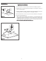
Appliance Installation:Appliance Installation:
Appliance Installation:Appliance Installation:
Appliance Installation:
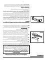
11. Install transition on top of hood if removed for shipping. Figure 4.
12. Hang hood on 2 mounting hooks through the rectangular cutouts on
back of hood. Figure 5
13. Level the appliance, using a carpenters level across bottom of hood with
leveling screws in mounting hooks or rectangular cutouts.
14. Secure hood with 2 screws on top and 2 screws on bottom. See Figure 5.
15. Connect ducting (Figure 4).
Note: for blower serviceability, leave a gap of 1" minimum between top
of transition and sheet metal duct and cover gap with a starting collar
wrapped around duct and transition. Locate collar screws so they fit into
corner of duct cover. Secure collar to transition and duct with three sheet
metal screws each. Seal with duct tape.
Do not use duct smaller than the transition.Do not use duct smaller than the transition.
Do not use duct smaller than the transition.Do not use duct smaller than the transition.
Do not use duct smaller than the transition.
Starting
Collar
1"
13
Figure 4Figure 4
Figure 4Figure 4
Figure 4
Figure 5Figure 5
Figure 5Figure 5
Figure 5

7
InstallationInstallation
InstallationInstallation
Installation
Wiring to Power SupplyWiring to Power Supply
Wiring to Power SupplyWiring to Power Supply
Wiring to Power Supply
WARNING!WARNING!
WARNING!WARNING!
WARNING!
ELECTRICAL GROUNDING INSTRUCTIONSELECTRICAL GROUNDING INSTRUCTIONS
ELECTRICAL GROUNDING INSTRUCTIONSELECTRICAL GROUNDING INSTRUCTIONS
ELECTRICAL GROUNDING INSTRUCTIONS
THIS APPLIANCE IS FITTED WITH AN ELECTRICAL JUNCTION BOX WITH
3 WIRES, ONE OF WHICH (GREEN/YELLOW) SERVES TO GROUND THE
APPLIANCE. TO PROTECT YOU AGAINST ELECTRIC SHOCK, THE GREEN
AND YELLOW WIRE MUST BE CONNECTED TO THE GROUNDING WIRE
IN YOUR
HOME ELECTRICAL SYSTEM, AND IT MUST UNDER NO CIRCUMSTANCES
BE CUT OR REMOVED.
Warning: Turn off power circuit at the service panel before wiring this unit.
120 VAC, 15 or 20 Amp circuit required.
16.16.
16.16.
16. Remove the knockout and install the conduit connector (1/2") in junction
box.
17.17.
17.17.
17. Run 3 wires; black, white and green (#16AWG) in 1/2" conduit from
service panel to junction box.
18.18.
18.18.
18. Connect black wire from service panel to black or red in junction box,
white to white and green to green-yellow. Figure 6.
19.19.
19.19.
19. Close junction box cover. Check all light bulbs to make sure they are
secure in their sockets. Turn power on in service panel. Check lights and
blower operation per Care & Use section of this manual. Install filters.
Final AssemblyFinal Assembly
Final AssemblyFinal Assembly
Final Assembly
20.20.
20.20.
20. Install duct cover per Figure 3. Make sure to leave this manual for the
home owner.
21.21.
21.21.
21. Make sure to leave this manual for the home owner.
Alternate - reduced ceiling height Installation:Alternate - reduced ceiling height Installation:
Alternate - reduced ceiling height Installation:Alternate - reduced ceiling height Installation:
Alternate - reduced ceiling height Installation:
The hood may be installed with only the lower part of the duct cover to
reduce the overall height.
For the duct cover to slide down and engage the top of the hood, the ceiling
bracket must be mounted 1/4" below the ceiling.
The resulting space on top of the chimney can be filled with a 1/4” thick piece
of plywood cut to the inside cross section of the chimney cover and finished
to match the ceiling.
Cut the self-adhesive rubber tape supplied with the hood in 4 identical
sections. Attach two pieces of tape to each side of the ceiling bracket. Figure
7.
Snap lower chimney duct cover into place around ceiling bracket.
Rear discharge:Rear discharge:
Rear discharge:Rear discharge:
Rear discharge:
A 90° elbow may be installed immediately above the hood. For serviceability,
a mounting similar to the straight up discharge shown in Figure 4 should be
used.
Figure 6Figure 6
Figure 6Figure 6
Figure 6
Figure 7Figure 7
Figure 7Figure 7
Figure 7

8
Use and CareUse and Care
Use and CareUse and Care
Use and Care
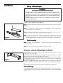
Operating InstructionsOperating Instructions
Operating InstructionsOperating Instructions
Operating Instructions
The blower should be turned on for about 5 minutes
beforebefore
beforebefore
before cooking in
order to establish air currents upward through the hood.
Use the low speeds for normal use and the higher speeds for strong odors or
fumes.
Minimize cross drafts which will reduce the effectiveness of the hood.
READ THE INSTRUCTIONS CAREFULLY BEFORE USING THE HOOD.
For satisfactory use of your hood, become familiar with the various functions
of the hood as described below
A. Light ON-OFF switch
B. Motor ON-OFF switch
C. Motor OFF
D. Motor speed 1 (low)
E. Motor speed 2 (med)
F. Motor speed 3 (high)
G. Motor speed 4 (very high)
AA
AA
A
BB
BB
B
CC
CC
C
DD
DD
D
EE
EE
E
FF
FF
F
GG
GG
G
Figure 8Figure 8
Figure 8Figure 8
Figure 8
Be sure lights are cool before cleaning the hood.
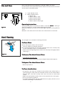
To Clean FiltersTo Clean Filters
To Clean FiltersTo Clean Filters
To Clean Filters
••
••
• The metal grease filters will last forever.
They are made of anodized aluminum
••
••
• It is recommended that the filters be washed at least once a month; they
can be washed by hand or in the dishwasher.
• Drain water through edge holes and let each filter dry thoroughly before
replacing it.
To Remove The Metal Grease FiltersTo Remove The Metal Grease Filters
To Remove The Metal Grease FiltersTo Remove The Metal Grease Filters
To Remove The Metal Grease Filters
• Turn blower and lights off.
• Push each handle towards the center and pull downwards Figure 9.
To Replace The Metal Grease FiltersTo Replace The Metal Grease Filters
To Replace The Metal Grease FiltersTo Replace The Metal Grease Filters
To Replace The Metal Grease Filters
• Reverse procedure.
To Clean Hood SurfaceTo Clean Hood Surface
To Clean Hood SurfaceTo Clean Hood Surface
To Clean Hood Surface
• For general care, wipe the outside of the stainless steel, white, black or
glass hood with sudsy water or household cleaners such as Fantastic® or
Formula 409
®
, rinse well and dry with clean soft cloth to avoid water
marks.
• Wipe and dry brushed stainless steel in the same direction as the grain.
• Do not use abrasive products.
• To remove finger prints and give added shine use spray cleaners such as
Stainless Steel Magic
®
and Shimmer
®
.
a
b
Figure 9Figure 9
Figure 9Figure 9
Figure 9
Hood CleaningHood Cleaning
Hood CleaningHood Cleaning
Hood Cleaning

9
NOTE:
Turn blower and lights off. Make sure the lights are cool.Turn blower and lights off. Make sure the lights are cool.
Turn blower and lights off. Make sure the lights are cool.Turn blower and lights off. Make sure the lights are cool.
Turn blower and lights off. Make sure the lights are cool. If new
lights do not operate be sure lights are inserted correctly before calling
service.
• Using a flat head screwdriver or equivalent tool, carefully pry loose the
light cover.
• Remove the damaged light and replace with a new 12 Volt, 20 Watt
(maximum) halogen light made for a G-4 base. Follow package directions
and do not touch new light with bare hands.
• Reinstall the light cover.
Lights replacementLights replacement
Lights replacementLights replacement
Lights replacement
Figure 10Figure 10
Figure 10Figure 10
Figure 10
Figure 10Figure 10
Figure 10Figure 10
Figure 10

10

11

In the U.S.A., your appliance is warranted by Electrolux Home Products North America, a division of White Consolidated Industries, Inc. We
authorize no person to change or add to any of our obligations under this warranty. Our obligations for service and parts under this warranty must
be performed by us or an authorized Electrolux Home Products North America servicer. In Canada, your appliance is warranted by WCI Canada,
Inc.
This warranty applies only to products in ordinary household use, and the consumer is responsible for the
items listed below:
1. Proper use of the appliance in accordance with instructions provided with the product.
2. Proper installation by an authorized servicer in accordance with instructions provided with the appliance and in
accordance with all local plumbing, electrical and/or gas codes.
3. Proper connection to a grounded power supply of sufficient voltage, replacement of blown fuses, repair of loose
connections or defects in house wiring.
4. Expenses for making the appliance accessible for servicing, such as removal of trim, cupboards, shelves,etc.,
which are not a part of the appliance when it was shipped from the factory.
5. Damages to finish after installation.
6. Replacement of light bulbs and/or fluorescent tubes (on models with these features).
This warranty does not cover the following:
1. CONSEQUENTIAL OR INCIDENTAL DAMAGES SUCH AS PROPERTY DAMAGE AND INCIDENTAL EXPENSES
RESULTING FROM ANY BREACH OF THIS WRITTEN OR ANY IMPLIED WARRANTY.
NOTE: Some states do not allow the exclusion or limitation of incidental or consequential damages, so this
limitation or exclusion may not apply to you.
2. Service calls which do not involve malfunction or defects in workmanship or material, or for appliances not in
ordinary household use. The consumer shall pay for such service calls.
3. Damages caused by services performed by servicers other than Electrolux Home Products North America or its
authorized servicers; use of parts other than genuine Electrolux Home Products parts; obtained from persons
other than such servicers; or external causes such as abuse, misuse, inadequate power supply or acts of God.
4. Products with original serial numbers that have been removed or altered and cannot be readily determined.
Keep your bill of sale, delivery slip, or some other appropriate payment record. The date on the bill establishes the
warranty period should service be required. If service is performed, it is in your best interest to obtain and keep all
receipts. This written warranty gives you specific legal rights. You may also have other rights that vary from state to state.
Service under this warranty must be obtained by contacting Electrolux Home Products:
*NORMAL
RESPONSIBILITIES
OF THE CONSUMER
EXCLUSIONS
IF YOU NEED
SERVICE
This warranty only applies in the 50 states of the U.S.A., Puerto Rico, and Canada. Product features or specifications as described or illustrated are
subject to change without notice. All warranties are made by Electrolux Home Products North America, a division of White Consolidated Industries,
Inc. In Canada, your appliance is warranted by WCI Canada, Inc.
RANGE HOOD WARRANTY
Your range hood is protected by this warranty
03-U-RH-02
USA
800•944•9044
Electrolux Home Products North America
P.O. Box 212378
Augusta, GA 30917
Canada
866•213•9397 (English)
866•294•9911 (French)
Electrolux Home Products North America
6150 McLaughlin Road
Mississauga, Ontario, Canada
L5R 4C2
12

12
GARANTIE DE LA HOTTE DE CUISINEGARANTIE DE LA HOTTE DE CUISINE
GARANTIE DE LA HOTTE DE CUISINEGARANTIE DE LA HOTTE DE CUISINE
GARANTIE DE LA HOTTE DE CUISINE
La hotte de cuisine que vous avez acheté est couverte par la présente garantie
USAUSA
USAUSA
USA
800•944•9044800•944•9044
800•944•9044800•944•9044
800•944•9044
Electrolux Home Products North America
P.O. Box 212378
Augusta, GA 30917
La présente garantie est valable uniquement dans les 50 Pays qui constituent les Etats-Unis d’Amérique, au Porto Rico et au Canada. Les
caractéristiques et les spécifications techniques décrites ou illustrées pour les produits sont peuvent subir des variations, et cela sans
préavis. Toutes les garanties offertes sont assurées par Electrolux Home Products North America, une division de White Consolidated
Industries, Inc. In Canada, l’appareil bénéficie de la garantie de WCI Canada, Inc.
*RESPONSABILITÉ*RESPONSABILITÉ
*RESPONSABILITÉ*RESPONSABILITÉ
*RESPONSABILITÉ
DE L’ACHETEURDE L’ACHETEUR
DE L’ACHETEURDE L’ACHETEUR
DE L’ACHETEUR
L’appareil acheté aux Etats-Unis est couvert par la garantie Electrolux Home Products North America, une division de White Consolidated
Industries, Inc. Les soussignés n’autorisent aucune modification ou adjonction aux obligations assumées en vertu de la présente garantie.
L’accomplissement des obligations assumées pour le service après-vente et la fourniture de pièces de rechange en vertu de la présente
garantie est exclusivement du ressort des soussignés ou d’un centre de service après-vente autorisé par Electrolux Home Products North
America. Au Canada, l’appareil acheté est couvert par la garantie WCI Canada, Inc.
La présente garantie concerne uniquement les produits destinés à un emploi normal dans un contexteLa présente garantie concerne uniquement les produits destinés à un emploi normal dans un contexte
La présente garantie concerne uniquement les produits destinés à un emploi normal dans un contexteLa présente garantie concerne uniquement les produits destinés à un emploi normal dans un contexte
La présente garantie concerne uniquement les produits destinés à un emploi normal dans un contexte
domestique et elle attribue à l’acheteur les responsabilités suivantes:domestique et elle attribue à l’acheteur les responsabilités suivantes:
domestique et elle attribue à l’acheteur les responsabilités suivantes:domestique et elle attribue à l’acheteur les responsabilités suivantes:
domestique et elle attribue à l’acheteur les responsabilités suivantes:
1.1.
1.1.
1. Emploi correct de l’appareil, conformément aux instructions fournies avec le produit.
2.2.
2.2.
2. Installation correcte effectuée par un centre de service après-vente autorisé, conformément aux instructions
fournies avec l’appareil et en plein respect des règlements locaux en matière d’installations électriques,
hydrauliques et/ou du gaz.
3.3.
3.3.
3. Connexion à une source d’alimentation avec mise à la terre ayant une tension appropriée, remplacement des
fusibles grillés, réparation des connexions interrompues ou rectification des pannes de l’installation
électrique domestique.
4.4.
4.4.
4. Frais soutenus afin de garantir l’accès à l’appareil pour les interventions d’entretien ou de réparation, y
compris le retrait de fournitures, meubles, armoires suspendues, etc. qui ne font pas partie de l’appareil au
moment de la livraison de la part de l’usine de production.
5.5.
5.5.
5. Dommages aux finitions à la suite de l’installation.
6.6.
6.6.
6. Remplacement des lampes et/ou tubes fluorescents (sur les modèles équipés de ces éléments).
La présente garantie n’intervient pas dans les cas suivants:La présente garantie n’intervient pas dans les cas suivants:
La présente garantie n’intervient pas dans les cas suivants:La présente garantie n’intervient pas dans les cas suivants:
La présente garantie n’intervient pas dans les cas suivants:
1.1.
1.1.
1. DOMMAGES DÉCLARÉS OU INDIRECTS, PARMI LESQUELS LES DOMMAGES À LA PROPRIÉTÉ, ET LES FRAIS
INDIRECTS DÉRIVANT DE LA VIOLATION DE LA PRÉSENTE GARANTIE ÉCRITE OU DE TOUTE AUTRE GARANTIE
IMPLICITE.
REMARQUE: REMARQUE:
REMARQUE: REMARQUE:
REMARQUE: Certains Pays n’autorisent pas l’exclusion ou la limitation des dommages déclarés ou indirects
par rapport à la garantie. Pour ce motif, ladite exclusion ou limitation peut ne pas concerner l’appareil que
vous avez acheté.
2.2.
2.2.
2. Appels au service après-vente ne concernant pas le fonctionnement défectueux ou les défauts du matériau/
de l’usinage ou relatifs aux appareils non destinés à l’emploi normal dans le contexte domestique. L’acheteur
est tenu de régler le paiement pour lesdits appels au service après-vente.
3.3.
3.3.
3. Dommages consécutifs aux prestations des techniciens d’un service après-vente non appartenant à Electrolux
Home Products North America ou à ses centres autorisés; emploi de pièces de rechange non originales
obtenues dans des centres non appartenant à Electrolux Home Products; causes externes telles que: abus,
emploi impropre, installation d’alimentation non appropriée ou causes de force majeure.
4.4.
4.4.
4. Produits dont les numéros de série originaux ont été retirés ou altérés et ne pouvant pas être identifiés
immédiatement.
Conserver la facture d’achat, le bulletin de livraison ou tout autre reçu attestant le paiement. La date reportée
sur la facture établit les termes de la validité de la garantie pour la demande d’assistance. Il est dans vos
intérêts d’obtenir et conserver tous les reçus, dans l’éventualité où une intervention du service après-vente
devait se révéler nécessaire. La présente garantie écrite vous confère des droits légaux spécifiques. Des droits
ultérieurs pourront vous être conférés sur la base de la législation en vigueur dans les différents Pays. pour la
demande d’assistance en garantie, s’adresser à Electrolux Home Products:
CanadaCanada
CanadaCanada
Canada
866•213•9397 (Anglais)866•213•9397 (Anglais)
866•213•9397 (Anglais)866•213•9397 (Anglais)
866•213•9397 (Anglais)
866•294•9911 (Français)866•294•9911 (Français)
866•294•9911 (Français)866•294•9911 (Français)
866•294•9911 (Français)
Electrolux Home Products North America
6150 McLaughlin Road
Mississauga, Ontario, Canada
L5R 4C2
EXCLUSIONSEXCLUSIONS
EXCLUSIONSEXCLUSIONS
EXCLUSIONS
SI L’ON DEMANDESI L’ON DEMANDE
SI L’ON DEMANDESI L’ON DEMANDE
SI L’ON DEMANDE
ASSISTANCEASSISTANCE
ASSISTANCEASSISTANCE
ASSISTANCE
PÉRIODEPÉRIODE
PÉRIODEPÉRIODE
PÉRIODE
DE GARANTIEDE GARANTIE
DE GARANTIEDE GARANTIE
DE GARANTIE
SERVICES OFFERTS À TRAVERS NOS CENTRES DESERVICES OFFERTS À TRAVERS NOS CENTRES DE
SERVICES OFFERTS À TRAVERS NOS CENTRES DESERVICES OFFERTS À TRAVERS NOS CENTRES DE
SERVICES OFFERTS À TRAVERS NOS CENTRES DE
SERVICE APRÈS-VENTE AUTORISÉS:SERVICE APRÈS-VENTE AUTORISÉS:
SERVICE APRÈS-VENTE AUTORISÉS:SERVICE APRÈS-VENTE AUTORISÉS:
SERVICE APRÈS-VENTE AUTORISÉS:
RESPONSABILITÉ DE L’ACHETEUR :RESPONSABILITÉ DE L’ACHETEUR :
RESPONSABILITÉ DE L’ACHETEUR :RESPONSABILITÉ DE L’ACHETEUR :
RESPONSABILITÉ DE L’ACHETEUR :
GARANTIE TOTALEGARANTIE TOTALE
GARANTIE TOTALEGARANTIE TOTALE
GARANTIE TOTALE
D’UNE ANNÉED’UNE ANNÉE
D’UNE ANNÉED’UNE ANNÉE
D’UNE ANNÉE
GARANTIE LIMITÉEGARANTIE LIMITÉE
GARANTIE LIMITÉEGARANTIE LIMITÉE
GARANTIE LIMITÉE
(applicable pour(applicable pour
(applicable pour(applicable pour
(applicable pour
l’Alaska)l’Alaska)
l’Alaska)l’Alaska)
l’Alaska)
Une année à compter de
la date d’achat initiale.
Couverture de tous les frais de réparation ou
remplacement des pièces de l’appareil qui se révèlent
défectueuses au niveau des matériaux ou de
l’usinage.
Paiement des frais pour les appels au service
après-vente indiqués dans le paragraphe
“RESPONSABILITÉS NORMALES DE
L’ACHETEUR”.
Périodes indiquées
ci-dessus
Paiement des frais de déplacement et
d’intervention du technicien au domicile de
l’acheteur ainsi que les frais de retrait et de
livraison de l’appareil pour le service après-
vente.
Couverture des frais sur la base des clauses des
garanties totales et limitées mentionnées ci-dessus et
des exclusions de garantie indiquées ci-dessous.

11

10
REMARQUE:
Éteindre le rotor et les lampes. S’assurer que les lampesÉteindre le rotor et les lampes. S’assurer que les lampes
Éteindre le rotor et les lampes. S’assurer que les lampesÉteindre le rotor et les lampes. S’assurer que les lampes
Éteindre le rotor et les lampes. S’assurer que les lampes
soient froides. soient froides.
soient froides. soient froides.
soient froides. Si les lampes neuves ne fonctionnent pas, vérifier qu’elles
soient insérées correctement avant de contacter le Service après-vente.
• En utilisant un tournevis à tête plate ou un outil équivalent, retirer le
plafonnier, en faisant très attention.
• Retirer la lampe endommagée puis remplacer celle-ci par une lampe
halogène 12 Volts, 20 Watt (maximum) pour un socle G-4. Suivre les
instructions reportées sur l’emballage. Ne pas toucher la lampe neuve des
mains nues.
• Remonter le plafonnier.
RemplacementRemplacement
RemplacementRemplacement
Remplacement
des lampesdes lampes
des lampesdes lampes
des lampes
Figure 10Figure 10
Figure 10Figure 10
Figure 10
Figure 10Figure 10
Figure 10Figure 10
Figure 10

9
Emploi er EntretienEmploi er Entretien
Emploi er EntretienEmploi er Entretien
Emploi er Entretien
Instructions relatives au fonctionnementInstructions relatives au fonctionnement
Instructions relatives au fonctionnementInstructions relatives au fonctionnement
Instructions relatives au fonctionnement
Nous conseillons d’allumer le rotor de ventilation environ 5 minutes
avantavant
avantavant
avant
de commencer la cuisson, afin d’activer le tirage des courants d’air à travers
la hotte.
Définir une vitesse réduite pour les conditions d’emploi normales et une
vitesse plus élevée en cas de fumée ou odeurs intenses.
Réduire au maximum les courants de tirage transversaux susceptibles deRéduire au maximum les courants de tirage transversaux susceptibles de
Réduire au maximum les courants de tirage transversaux susceptibles deRéduire au maximum les courants de tirage transversaux susceptibles de
Réduire au maximum les courants de tirage transversaux susceptibles de
réduire l’efficacité de la hotte.réduire l’efficacité de la hotte.
réduire l’efficacité de la hotte.réduire l’efficacité de la hotte.
réduire l’efficacité de la hotte.
LIRE ATTENTIVEMENT LES INSTRUCTIONS AVANT D’UTILISER LA HOTTE.
Afin de pouvoir utiliser la hotte de façon satisfaisante il faut se
familiariser avec toutes ses fonctions:
A. Interrupteur ON/OFF d’allumage et extinction des
lumières
B. Interrupteur ON-OFF d’allumage et extinction du
moteur
C. Moteur éteint (OFF)
D. Vitesse moteur 1 (faible)
E. Vitesse moteur 2 (moyenne)
F. Vitesse moteur 3 (grande)
G. Vitesse moteur 4 (très grande)
AA
AA
A
BB
BB
B
CC
CC
C
DD
DD
D
EE
EE
E
FF
FF
F
GG
GG
G
Figure 8Figure 8
Figure 8Figure 8
Figure 8
S’assurer que les lampes se soient refroidies avant d’effectuer le nettoyage
de la hotte.
Nettoyage des filtresNettoyage des filtres
Nettoyage des filtresNettoyage des filtres
Nettoyage des filtres
••
••
• Les filtres métalliques anti-graisse sont réalisés en aluminium anodisé et
leur durée de vie est illimitée.
••
••
• Nous recommandons de nettoyer les filtres au moins une fois pas mois. Les
filtres peuvent être lavés à la main ou au lave-vaisselle.
• Évacuer l’eau à travers les trous sur le bord puis laisser sécher totalement
les filtres avant de les remonter.
Retrait des filtres métalliques anti-graisseRetrait des filtres métalliques anti-graisse
Retrait des filtres métalliques anti-graisseRetrait des filtres métalliques anti-graisse
Retrait des filtres métalliques anti-graisse
• Éteindre le rotor de ventilation et les lampes.
• Pousser chaque poignée au milieu et vers le bas (Figure 9).
Remplacement des filtres métalliques anti-graisseRemplacement des filtres métalliques anti-graisse
Remplacement des filtres métalliques anti-graisseRemplacement des filtres métalliques anti-graisse
Remplacement des filtres métalliques anti-graisse
• Suivre la procédure à rebours.
Nettoyage de la surface de la hotteNettoyage de la surface de la hotte
Nettoyage de la surface de la hotteNettoyage de la surface de la hotte
Nettoyage de la surface de la hotte
• Pour le nettoyage général des hottes blanches ou noies, en acier inox ou
en verre, passer sur la surface externe un chiffon imbibé d’eau savonneuse
ou de détergent pour emploi domestique (type Fantastic®, Formula 409
®
,
etc.), puis rincer avec soin et sécher avec un chiffon souple et sec afin
d’éliminer toute trace.
• Nettoyer puis sécher l’acier inox usiné, en suivant le sens de l’usinage.
• Ne pas utiliser des produits abrasifs.
• Pour éliminer les traces d’empreintes et intensifier l’éclat des surfaces,
utiliser des sprays détergents, par exemple: Stainless Steel Magic
®
et
Shimmer
®
.
a
b
Figure 9Figure 9
Figure 9Figure 9
Figure 9
Nettoyage de la HotteNettoyage de la Hotte
Nettoyage de la HotteNettoyage de la Hotte
Nettoyage de la Hotte

8
InstallationInstallation
InstallationInstallation
Installation
Branchement au réseau d’alimentation électriqueBranchement au réseau d’alimentation électrique
Branchement au réseau d’alimentation électriqueBranchement au réseau d’alimentation électrique
Branchement au réseau d’alimentation électrique
AVERTISSEMENTS!AVERTISSEMENTS!
AVERTISSEMENTS!AVERTISSEMENTS!
AVERTISSEMENTS!
INSTRUCTIONS POUR LE BRANCHEMENT ÉLECTRIQUE DE TERREINSTRUCTIONS POUR LE BRANCHEMENT ÉLECTRIQUE DE TERRE
INSTRUCTIONS POUR LE BRANCHEMENT ÉLECTRIQUE DE TERREINSTRUCTIONS POUR LE BRANCHEMENT ÉLECTRIQUE DE TERRE
INSTRUCTIONS POUR LE BRANCHEMENT ÉLECTRIQUE DE TERRE
LE PRÉSENT APPAREIL EST ÉQUIPÉ D’UNE BOÎTE DE CONNEXION
ÉLECTRIQUE ÉQUIPÉE DE 3 FILS, DONT UN (VERT/JAUNE) EST DESTINÉ À
LA CONNEXION DE TERRE DE L’APPAREIL.
POUR LA PROTECTION CONTRE LE RISQUE DE CHOCS ÉLECTRIQUES, LE
FIL VERT ET JAUNE DOIT ÊTRE CONNECTÉ AU FIL DE TERRE DE
L’INSTALLATION ÉLECTRIQUE DOMESTIQUE ET IL NE DOIT PAS – POUR
QUELQUE RAISON QUE CE SOIT – ÊTRE COUPÉ OU ENLEVÉ.
Avertissement: Avant de préparer les connexions électriques, interrompre le
circuit d’alimentation du panneau de commande. Alimentation requise: 120
V C.A., 15 ou 20 Amp.
16.16.
16.16.
16. Retirer la partie prédécoupée et installer le connecteur de la conduite (1/
2") dans la boîte de connexion.
17.17.
17.17.
17. Installer les 3 fils noir, blanc et vert (#16AWG) dans la conduite de 1/2"
entre le panneau de commandes et la boîte de connexion.
18.18.
18.18.
18. Connecter le fil noir du panneau de commandes au fil noir ou rouge de
la boîte de connexion, le fil blanc au fil blanc et le fil vert au fil vert/jaune
(Figure 6).
19.19.
19.19.
19. Fermer le couvercle de la boîte de connexion. Contrôler toutes les lampes
pour vérifier qu’elles soient correctement fixées aux douilles
correspondantes. Activer l’alimentation du panneau de commandes.
Contrôler les lampes et le fonctionnement du rotor de ventilation, en
suivant les instructions fournies dans la section Emploi et Entretien du
présent manuel. Installer les filtres.
Montage finalMontage final
Montage finalMontage final
Montage final
20.20.
20.20.
20. Installer la couverture de la conduite, comme décrit dans la Figure 3. Ne
pas oublier de laisser le présent manuel à disposition du propriétaire.
21.21.
21.21.
21. Ne pas oublier de laisser le présent manuel à disposition du propriétaire.
Installation alternative avec hauteur réduite par rapport auInstallation alternative avec hauteur réduite par rapport au
Installation alternative avec hauteur réduite par rapport auInstallation alternative avec hauteur réduite par rapport au
Installation alternative avec hauteur réduite par rapport au
plafond:plafond:
plafond:plafond:
plafond:
Il est également possible d’installer la hotte uniquement avec la partie
inférieure de la couverture de la conduite, de façon à réduire la hauteur
totale de l’installation. Pour faire en sorte que la couverture de la conduite
descende pour s’insérer sur la partie la plus haute de la hotte, il faut monter
la bride à une distance de 1/4" par rapport au plafond.
L’espace obtenu sur la partie la plus haute de la cheminée peut être remplie
avec un élément en contre-plaqué ayant une épaisseur de 1/4”, qui sera
coupé en fonction de la section interne de la couverture de la cheminée avec
finition parfaitement alignée avec le plafond.
Couper le ruban adhésif fourni avec la hotte en 4 parties ayant la même
longueur. Fixer deux bandes de ruban adhésif de chaque côté de la bride au
plafond (Figure 7).
Encliqueter la couverture de la conduite sur la bride.
Évacuation arrière:Évacuation arrière:
Évacuation arrière:Évacuation arrière:
Évacuation arrière:
Il est possible d’installer un coude à 90° immédiatement au-dessus de la
hotte. Afin de garantir l’efficacité du fonctionnement, nous conseillons
d’effectuer un montage analogue pour l’évacuation verticale illustrée
dans la Figure 4.
Figure 6Figure 6
Figure 6Figure 6
Figure 6
Figure 7Figure 7
Figure 7Figure 7
Figure 7

7
InstallationInstallation
InstallationInstallation
Installation
Installation de l’appareil:Installation de l’appareil:
Installation de l’appareil:Installation de l’appareil:
Installation de l’appareil:
11. Si le raccord a été retiré pour effectuer le transport, il faudra ensuite
l’installer sur la partie la plus haute de la hotte (Figure 4).
12. Suspendre la hotte aux 2 crochets de montage, en utilisant les ouvertures
rectangulaires qui se trouvent sur la partie arrière de la hotte (Figure 5).
13. Stabiliser l’appareil en appliquant un niveau sur le fond de la hotte et en
introduisant les vis de niveau spécialement prévues dans les crochets de
montage ou dans les ouvertures rectangulaires.
14. Fixer la hotte en appliquant 2 vis sur la partie la plus haute et 2 vis sur le
fond (Figure 5).
15. Connecter les canalisations (Figure 4).
Remarque: afin de garantir un fonctionnement correct du rotor de
ventilation, il faut laisser un espace minimum de 1” entre la partie la plus
haute du raccord et la conduite en tôle métallique puis recouvrir l’espace
avec un collier de connexion qu’il faudra insérer sur la conduite et le
raccord. Positionner les vis du collier de façon à ce qu’elles s’insèrent aux
coins de la couverture de la conduite. Fixer le collier contre la conduite
et le raccord, au moyen de trois vis à métal pour chaque pièce et, pour
terminer, sceller avec du ruban spécial pour tuyaux.
Ne pas utiliser un tuyau plus petit du raccord.Ne pas utiliser un tuyau plus petit du raccord.
Ne pas utiliser un tuyau plus petit du raccord.Ne pas utiliser un tuyau plus petit du raccord.
Ne pas utiliser un tuyau plus petit du raccord.
Anneau de
connexion
1"
13
Figure 4Figure 4
Figure 4Figure 4
Figure 4
Figure 5Figure 5
Figure 5Figure 5
Figure 5

6
InstallationInstallation
InstallationInstallation
Installation
Préparation de la surface de montage (placoplâtre)Préparation de la surface de montage (placoplâtre)
Préparation de la surface de montage (placoplâtre)Préparation de la surface de montage (placoplâtre)
Préparation de la surface de montage (placoplâtre)
1. Choisir une hauteur pour le montage pratique pour l’utilisateur et
marquer cette dernière sur la paroi, derrière le plan de cuisson.
2. Marquer l’axe du plan de cuisson et tracer une ligne verticale allant du
fond de la hotte jusqu’au plafond.
3. Fixer le gabarit de perçage avec du ruban adhésif, en faisant correspondre
l’axe du plan de cuisson avec le fond de la hotte, comme illustré dans la
Figure 2.
4. À travers le gabarit de perçage, marquer au milieu les 6 positions de
fixation contre la paroi, puis retirer le gabarit.
5. Marquer une ligne horizontale sur la paroi, à une distance de 1” au-
dessus de la position de fixation la plus élevée et à 1” au-dessous de la
position de fixation la plus basse.
6. Localiser les couples du châssis derrière le placoplâtre en tapotant
légèrement la paroi ou en utilisant un «chercheur de châssis» spécial.
Marquer au milieu tous les couples du châssis, en traçant une ligne
verticale à droite et à gauche de la position de fixation marquée.
RemarqueRemarque
RemarqueRemarque
Remarque: Deux des six positions marquées doivent recouvrir au moins
2 couples du châssis, d’un côté à l’autre.
7. Percer le placoplâtre le long des lignes marquées. Installer 2 des 6
positions marquées entre les couples du châssis en les maintenant
parfaitement alignées avec le côté avant du couple. Veiller à ce que
toutes les vis de montage soient ancrées au bois dans lequel elles ont été
introduites. Reconstruire le placoplâtre puis effectuer le finissage.
8. Marquer l’axe du plan et le fond de la hotte en correspondance du même
point précédemment marqué puis fixer le gabarit de perçage contre la
paroi avec du ruban adhésif, comme décrit au point 3.
9. Fixer 2 crochets de montage avec des vis à bois (pièces fournies avec les
outils de montage) en correspondance des points marqués sur le gabarit,
puis retirer le gabarit de la paroi.
10. En utilisant les dispositifs d’ancrage fournis, installer la bride de support
pour la couverture de la conduite contre la paroi, en la maintenant
parfaitement alignée avec la bride (voir Figure 3).
Figure 2Figure 2
Figure 2Figure 2
Figure 2
C
L
16
16
Figure 3Figure 3
Figure 3Figure 3
Figure 3
Outils requis pour l’installationOutils requis pour l’installation
Outils requis pour l’installationOutils requis pour l’installation
Outils requis pour l’installation
Tournevis
(vis à tête plate, pozidrive n°2 et torx
10)
Clé pour vis Allen 4mm.
Perceuse électrique avec mèche
hélicoïdale de Ø 10 mm

5
InstallationInstallation
InstallationInstallation
Installation
UNIQUEMENT POUR EMPLOI RÉSIDENTIEL.UNIQUEMENT POUR EMPLOI RÉSIDENTIEL.
UNIQUEMENT POUR EMPLOI RÉSIDENTIEL.UNIQUEMENT POUR EMPLOI RÉSIDENTIEL.
UNIQUEMENT POUR EMPLOI RÉSIDENTIEL.
NE PAS INSTALLER SUR LES GRILLES AVEC CHAUFFAGE AU GAZ.NE PAS INSTALLER SUR LES GRILLES AVEC CHAUFFAGE AU GAZ.
NE PAS INSTALLER SUR LES GRILLES AVEC CHAUFFAGE AU GAZ.NE PAS INSTALLER SUR LES GRILLES AVEC CHAUFFAGE AU GAZ.
NE PAS INSTALLER SUR LES GRILLES AVEC CHAUFFAGE AU GAZ.
AVANT D’UTILISER L’APPAREIL, LIRE ATTENTIVEMENT LES PRÉSENTES INSTRUCTIONS.AVANT D’UTILISER L’APPAREIL, LIRE ATTENTIVEMENT LES PRÉSENTES INSTRUCTIONS.
AVANT D’UTILISER L’APPAREIL, LIRE ATTENTIVEMENT LES PRÉSENTES INSTRUCTIONS.AVANT D’UTILISER L’APPAREIL, LIRE ATTENTIVEMENT LES PRÉSENTES INSTRUCTIONS.
AVANT D’UTILISER L’APPAREIL, LIRE ATTENTIVEMENT LES PRÉSENTES INSTRUCTIONS.
L’INSTALLATION DOIT ÊTRE EFFECTUÉE CONFORMÉMENT AUX REGLEMENTS LOCAUX.L’INSTALLATION DOIT ÊTRE EFFECTUÉE CONFORMÉMENT AUX REGLEMENTS LOCAUX.
L’INSTALLATION DOIT ÊTRE EFFECTUÉE CONFORMÉMENT AUX REGLEMENTS LOCAUX.L’INSTALLATION DOIT ÊTRE EFFECTUÉE CONFORMÉMENT AUX REGLEMENTS LOCAUX.
L’INSTALLATION DOIT ÊTRE EFFECTUÉE CONFORMÉMENT AUX REGLEMENTS LOCAUX.
IMPORTANT:IMPORTANT:
IMPORTANT:IMPORTANT:
IMPORTANT: Conserver les présentes instructions pour l’emploi destinées à l’Inspecteur de la société électrique.
INSTALLATEUR:INSTALLATEUR:
INSTALLATEUR:INSTALLATEUR:
INSTALLATEUR: Conserver avec l’appareil les présentes instructions pour l’emploi destinées au propriétaire.
PROPRIÉTAIRE:PROPRIÉTAIRE:
PROPRIÉTAIRE:PROPRIÉTAIRE:
PROPRIÉTAIRE: Conserver les présentes instructions pour toute éventuelle consultation à l’avenir.
Avertissements concernant la sécurité: Avant d’effectuer le branchement de l’appareil, couper le circuit
d’alimentation et bloquer le panneau de commandes.
Alimentation requise: 120 V C.A., 60 Hz. 15 ou 20 A
Poids: 42 lbs
Diamètre de raccordement: 6”
Diamètre requis pour la conduite d’évacuation: 6”
DimensionsDimensions
DimensionsDimensions
Dimensions
Avant d’effectuer l’installation de la hotteAvant d’effectuer l’installation de la hotte
Avant d’effectuer l’installation de la hotteAvant d’effectuer l’installation de la hotte
Avant d’effectuer l’installation de la hotte
1. Afin d’obtenir une efficacité maximum d’évacuation de l’air, utiliser une
conduite linéaire ou réduire au maximum le nombre des coudes présents.
ATTENTION:ATTENTION:
ATTENTION:ATTENTION:
ATTENTION: Évacuer l’air de l’unité exclusivement à l’extérieur de
l’édifice.
2. Utiliser des canalisations flexibles en métal, si autorisées dans votre région,
uniquement pour connecter la conduite rigide directement aux dispositifs
de raccordement.
3. Les équipements installés dans des régions au CLIMAT FROID doivent avoir
un clapet de retenue des fumées pour réduire au maximum l’écoulement
de l’air froid de retour, outre à une protection thermique non métallique
pour minimiser l’influence de la température externe à travers le réseau
des canalisations. Il est opportun d’installer le clapet sur le côté de l’air
froid de la protection thermique et de placer la protection le plus près
possible du point d’entrée des canalisations dans la partie réchauffée de
l’édifice.
4. La hauteur pour l’installation de la hotte sur le plan de la cuisine doit être
établie en fonction des exigences de l’utilisateur. Plus la hotte sera placée
en bas, par rapport à la cuisine, plus l’aspiration des vapeurs et des odeurs
de cuisson, de la graisse et de la fumée sera efficace. Nous recommandons
d’installer la hotte à une hauteur de 30-36" par rapport au plan de cuisson.
Une installation à une hauteur inférieure pourrait se révéler inconfortable
pour les personnes très grandes et peu pratique lors de l’emploi de
récipients particulièrement amples. Avant de choisir la hotte, vérifier la
hauteur du plafond et la hauteur maximum utilisable par rapport à la
hotte.
Figure 1*Figure 1*
Figure 1*Figure 1*
Figure 1*
Remarque: Toutes les
dimensions sont exprimées
en pouces.
* Les dimensions sont
calculées en partant de la
base de la hotte jusqu’au
plafond et elles comprennent
l’espace libre requis pour
l’installation.
Dimensions
A (Intervalle de réglage hauteur)* 33
7
/
16
- 42
3
/
8
B (
Hauteur minimum avec une seule couverture
)* 26
W (largeur) x D (profondeur) 8
3
/
16
x 6
7
/
8
AA (Hauteur réglable couverture) 23
7
/
16
- 32
15
/
16
BB (Hauteur minimum couverture) 16
La page est en cours de chargement...
La page est en cours de chargement...
La page est en cours de chargement...
La page est en cours de chargement...
-
 1
1
-
 2
2
-
 3
3
-
 4
4
-
 5
5
-
 6
6
-
 7
7
-
 8
8
-
 9
9
-
 10
10
-
 11
11
-
 12
12
-
 13
13
-
 14
14
-
 15
15
-
 16
16
-
 17
17
-
 18
18
-
 19
19
-
 20
20
-
 21
21
-
 22
22
-
 23
23
-
 24
24


Frigidaire PLHV36W6KC Manuel utilisateur
- Catégorie
- Hottes
- Taper
- Manuel utilisateur
dans d''autres langues
- English: Frigidaire PLHV36W6KC User manual