Best PIK33 Guide d'installation
- Catégorie
- Hottes
- Taper
- Guide d'installation

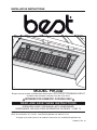
MODEL PIK33D
SUITABLE FOR USE IN DAMP LOCATIONS WHEN INSTALLED IN A GFCI PROTECTED BRANCH-CIRCUIT.
INTENDED FOR OUTDOOR COVERED PATIO OR LANAI AREA.
INTENDED FOR DOMESTIC COOKING ONLY
INSTALLER: LEAVE THIS MANUAL WITH HOMEOWNER.
HOMEOWNER: USE AND CARE INFORMATION ON PAGES 11 AND 12.
BEST; Hartford, Wisconsin www.BestRangeHoods.com 800-558-1711
BEST; Drummondville, QC, Canada www.BestRangeHoods.com 866-737-7770
To register your product online or for additional information visit: www.BestRangeHoods.com
SV06322 Rev. 10
HB0034
INSTALLATION INSTRUCTIONS
READ AND SAVE THESE INSTRUCTIONS
!
!

WARNING WARNING
- 2 -
TO REDUCE THE RISK OF FIRE, ELECTRIC
SHOCK OR INJURY TO PERSONS, OBSERVE THE
FOLLOWING:
1. Use this unit only in the manner intended by the
manufacturer. If you have questions, contact the
manufacturer at the address or telephone number
listed in the warranty.
2. Before servicing or cleaning unit, switch power off at
service panel and lock service disconnecting means to
prevent power from being switched on accidentally.
When the service disconnecting means cannot be
locked, securely fasten a prominent warning device,
such as a tag, to the service panel.
3. Installation work and electrical wiring must be done by
qualified personnel in accordance with all applicable
codes and standards, including fire-rated construction
codes and standards.
4. Sufficient air is needed for proper combustion and
exhausting of gases through the flue (chimney) of fuel
burning equipment to prevent backdrafting. Follow the
heating equipment manufacturer’s guidelines and
safety standards such as those published by the
National Fire Protection Association (NFPA) and the
American Society for Heating, Refrigeration and Air
Conditioning Engineers (ASHRAE) and the local code
authorities.
5. When cutting or drilling into wall or ceiling, do not
damage electrical wiring and other hidden utilities.
6. Ducted fans must always be vented to the outdoors.
7. Do not use this unit with any other solid-state speed
control device.
8. To reduce the risk of fire, use only metal ductwork.
9. This unit must be grounded and protected by a GFCI.
10. Suitable for use in damp locations only when installed
in a GFCI PROTECTED branch-circuit.
11. When applicable local regulations comprise more
restrictive installation and/or certification requirements,
the aforementioned requirements prevail on those of
this document and the installer agrees to conform to
these at his own expenses.
TO REDUCE THE RISK OF A RANGE TOP
GREASE FIRE:
a) Never leave surface units unattended at high
settings. Boilovers cause smoking and greasy
spillovers that may ignite. Heat oils slowly on low or
medium settings.
b) Always turn hood ON when cooking at high heat or
when flambeing food (i.e.: Crêpes Suzette, Cherries
Jubilee, Peppercorn Beef Flambé).
c) Clean ventilating fans frequently. Grease should
not be allowed to accumulate on fan, filters or in
exhaust ducts.
d) Use proper pan size. Always use cookware
appropriate for the size of the surface element.
TO REDUCE THE RISK OF INJURY TO PERSONS
IN THE EVENT OF A RANGE TOP GREASE FIRE,
OBSERVE THE FOLLOWING*:
1. SMOTHER FLAMES with a close-fitting lid cookie
sheet or metal tray, then turn off the burner. BE
CAREFUL TO PREVENT BURNS. IF THE FLAMES
DO NOT GO OUT IMMEDIATELY, EVACUATE AND
CALL THE FIRE DEPARTMENT.
2. NEVER PICK UP A FLAMING PAN—You may be
burned.
3. DO NOT USE WATER, including wet dishcloths or
towels—This could cause a violent steam explosion.
4. Use an extinguisher ONLY if
A. You own a Class ABC extinguisher and you know
how to operate it.
B. The fire is small and contained in the area where it
started.
C. The fire department has been called.
D. You can fight the fire with your back to an exit.
*Based on “Kitchen Fire Safety Tips” published by NFPA.
CAUTION
1. For general ventilating use only. Do not use to exhaust
hazardous or explosive materials and vapors.
2. To avoid motor bearing damage and noisy and/or
unbalanced impellers, keep drywall spray, construction
dust, etc. off power unit.
3. Your insert motor has a thermal overload which will
automatically shut off the motor if it becomes
overheated. The motor will restart when it cools down.
If the motor continues to shut off and restart, have the
insert serviced.
4. The minimum hood distance above cooktop must not
be less than 36”. A maximum of 42” above cooktop is
highly recommended for best capture of cooking impurities.
5. Two installers are recommended because of the large
size and weight of this unit.
6. To reduce the risk of fire and to properly exhaust air, be
sure to duct air outside—Do not exhaust air into
spaces within walls or ceiling or into attics, crawl space
or garage.
7. This product is equipped with a thermostat which may
start blower automatically. To reduce the risk of injury
and to prevent power from being switched on
accidentally, switch power off at service panel and lock
or tag service panel.
8. To reduce the risk of fire and electric shock, the Best
model PIK33D must be installed only with interior
blower model P8D, exterior blower model EB12 or
EB15, or in-line blower model ILB11 (sold separately).
Other blowers cannot be substituted.
9. When used as demonstrator: use with approved
cord-connection kit only.
10. Please read specification label on product for further
information and requirements.
!
!

HL0080
- 3 -
Dual-blower P8D
(sold separately)
Model 410
(10” Round duct
2 ft. sections)
Model 418
(10” round adjustable
elbow, optional)
Model 441
(10” round
wall cap)
Model 421
(10” round vert. in-line damper)
(Recommended for use with
exterior blowers)
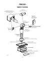
PIK33D INSERT
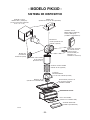
- PIK33D -
INSERT SYSTEM
Model ILB11 (1100 cfm)
In-line blower (includes two 8” x 12”
to 10’’ round transitions)
Model 437
(High capacity roof cap)
Model EB12
(1200 cfm) or
EB15 (1500 cfm)
Exterior blower
L3336D or L3348D
Custom Hood Liner (optional)
Rough-in plate
(supplied with interior blower P8D)
10” round metal
flexible duct
(optional)
Model SV03428
Transition (9” x 18” to 10” round) (included)
Flow deviator
(supplied with interior blower P8D)

- 4 -
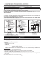
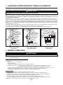
1. SELECT BLOWER OPTION AND INSTALL DUCTWORK
This insert is designed for use with gas or electric outdoor cooking appliances when operated in an outdoor covered patio or
lanai area. As with all electrical appliances, this unit must be protected from the effects of weather.
The insert model PIK33D must be installed with the interior blower P8D, or with the exterior blower model EB12 or EB15 or with
the in-line blower ILB11 only (sold separately). Other blowers cannot be substituted.
If installing in-line blower, refer to instructions packed with in-line blower and follow steps 1 up to 6, 10 up to 13, 15
and up of this manual.
Plan where and how the ductwork will be installed. Access to the top of the insertd is preferred for connection of ductwork. As
an alternative, flexible metal ductwork may be used.
Install 10” steel ductwork, elbows and roof or wall cap for the type of blower you are installing. Use round ductwork, with a short
section (about 4’ expanded) of flexible metal duct (optional) for attachment to the transition. Use screws to attach flexible metal
duct to the rigid duct. Use 2” metal foil duct tape to seal duct joints.
The minimum hood distance above cooktop must not be less than 36”. A maximum of 42” above cooktop is highly
recommended for best capture of cooking impurities.
Distances over 42” are at the installer and users discretion.
Insert with
interior
blower
Roof cap
Wall cap
HH0005A
10” round ducts
with 10” round
metal flex. duct
(optional)
9” x 18” to 10”
round transition
36” minimum
above
cooking surface
MODEL P8D
INTERIOR BLOWER
TYPICAL DUCTWORK
MODEL EB12, EB15
EXTERIOR BLOWER
TYPICAL DUCTWORK
MODEL ILB11
IN-LINE BLOWER
TYPICAL DUCTWORK
Insert
Exterior
blower
HH0042A
10” round duct
with 10” round
metal flex. duct
(optional)
9” x 18” to 10”
round transition
36” minimum
above
cooking surface
Exterior
blower
In-line blower
10” round duct
HH0067A
36” minimum
above
cooking surface
10” round
metal flex. duct
(optional)
Roof cap
Wall
cap
Insert
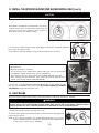
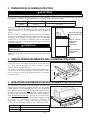
2. PREPARE THE INSTALLATION
NOTE: Before proceeding to the installation, check the contents of the box. If items are missing or damaged, contact the
manufacturer.
Make sure that the following items are included
:
- Insert
- Accessories:
• Transition (9” x 18” to 10” round)
• 3 Baffle filters
• 2 Shielded halogen bulbs (120 V, 50 W, type GU10)
• Bag of parts including: 3 waterproof wire connectors, 6 no. 10 x 2" hex head screws, 2 wire clamps LP16-AP,
8 no. 8 x 3/8" stainless steel screws.
Included in parts bag, but not to be used (please discard): 2 no. 8 x 5/8" screws, 4 no. 10 x 2" flat head screws,
2 wall anchors, 6 washers 3/16" ID x 3/4" OD, 4 stainless steel 10-32 locknuts, 2 no. 8 x 3/8" zinc-plated screws.
Parts sold separately
:
- Interior blower P8D with rough-in plate and flow deviator
- Exterior blower assembly EB12 or EB15 (do not use rough-in plate included with exterior blower)
- In-line blower assembly ILB11 (includes rough-in plate and 2 transitions, do not use the rough-in plate)
- Custom hood liner Model L3336D or L3348D (optional)
- Ductwork (rigid and flexible), elbows, dampers, wall and roof caps. Refer to page 3 for a complete list of venting options and
model numbers.
NOTE: During installation, protect countertop and/or cooktop.
WARNING
When performing installation, servicing or cleaning the unit, it is recommended to wear safety glasses and gloves.
WARNING
This unit is not designed for use with a charcoal grill.
!
!

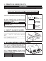
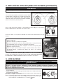
Start with the custom hood base, because its position will determine the
height of the insert. We recommend the base of the custom hood should be
3/4 inch thick plywood.
If an optional custom hood liner will be installed, we recommend the sides
and front of the custom hood to be 3/4 inch thick, assuming standard
cabinet widths. If the optional custom hood liner will not be installed, the
custom hood side and front thickness is at the installer’s discretion.
Run power cable to installation location.
Stub out a 4 foot length of electrical cable below the custom hood.
- 5 -
WARNING
The power cable must be a GFCI protected branch circuit.
!
Standard 36” h.
cooktop
HH0044A
36” to 42” above
cooking surface
Plywood base
thickness: 3/4”
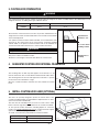
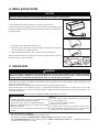
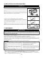
4. SUGGESTED CUSTOM HOOD INTERNAL FRAMEWORK
The mounting holes for both top stud supports are located at 11
9
⁄16” up
from the insert base. The on center distance between both studs is 30¼”.
The mounting holes for the rear stud support are located at 1½” up from
the insert base. See illustration at right.
Once the custom hood base and frame are done, finalize the custom
hood.
HH0043A
1½”
3. CUSTOM HOOD PREPARATION
The custom hood frame must be sized to the shape and total weight of the insert assembly. Refer to the table below for total
weight of the insert, according to the type of blower chosen.
WARNING
When building a custom hood, always follow all applicable construction codes and standards.
!
INSERT MODEL WITH INTERIOR BLOWER WITH EXTERIOR BLOWER OR IN-LINE BLOWER
PIK33D 49 LB. 27 LB.
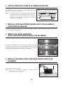
5. INSTALL CUSTOM HOOD LINER (OPTIONAL)
The liners are specially designed to protect the exterior base of the
custom hood. Both models are adjustable for depth from 23½” to 26½”
(front to back, without backboard).
The liner must be installed before
the insert. To order, refer to table
below to find the right liner model number for the custom hood width.
To view specific model information, including depths for each liner
model, visit www.BestRangeHoods.com
or contact Technical support
(phone number listed on page 14, in warranty text).
To install, see instructions packed with the custom hood liner.
HA0039A
INSERT MODEL CUSTOM HOOD NOMINAL WIDTH
L3336D 36”
L3348D 48”

- 6 -
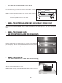
6. CUT THE HOLE IN CUSTOM HOOD BASE
If it is not done yet, cut a hole in the bottom of the cabinet, using the
dimensions shown at right.
NOTES: 1. The recommended distance from the back to the rearmost
cutout edge is 2¼” minimum.
2. When cutting the 10¾’’ notch for the wiring, also notch out the
rear stud or provide clearance for the wiring.
32½”
HD0101A
10¾”
2¼”
min.
11/16”
16½”
7. INSTALL THE EXTERNAL BLOWER (EB12, EB15 OR ILB11 MODELS ONLY)
Refer to instructions packed with EB12, EB15 or ILB11 external blowers and follow steps 10, 11, 12, 13, 15 and up of this
manual.
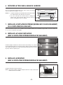
8. INSTALL THE ROUGH-IN PLATE
(USE WITH INTERIOR BLOWER P8D MODEL ONLY)
Hang the rough-in plate onto the insert inner top (screws through the large
part of the keyhole). Slide the rough-in plate toward the rear of insert (screws
in the smaller part of the keyhole). Tighten the (4) screws.
9. INSTALL THE DEVIATOR
(USE WITH INTERIOR BLOWER P8D MODEL ONLY)
Slide the deviator inside the insert as shown.
NOTE: If installed correctly, the deviator will protrude about 1/8” above the insert.
HO0022
HO0023

Connect wires as follow: BLACK to ORANGE (G), WHITE to 2 other WHITE wires (H), and
GREEN under ground screw (I). DO NOT FORGET TO CONNECT THE GROUND.
Reinstall the wiring box cover.
Connect wires as follow: BLACK to BLACK (C) and GREEN or BARE wire under ground screw (D). DO NOT FORGET TO
CONNECT THE GROUND. Do not reinstall the wiring box cover yet.
- 7 -
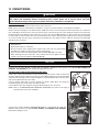
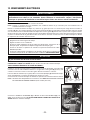
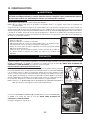
10. CONNECT WIRING
ALL INSTALLATIONS:
Punch out the knock-out hole(s) located on back side of the insert.
NOTE: Punch (1) hole for interior blower installation or (2) holes for exterior blower or in-line blower installation.
Remove the insert wiring box cover. Remove both flexible wire sleeves from the wiring box and keep for further use. Install one
wire clamp (A) on the back side of the insert and the other in the knock-out hole of the wiring box. Position insert below the
installed custom hood. Slide the power cable into one of the wire sleeves (B) provided. Pass power cable with sleeve through
the wire clamp on the back side of the insert and through the wire clamp in the wiring box. Tighten both wire clamps completely
to secure the cable. The wire sleeve ends must be secured by the wire clamps. Connect cable into wiring box using provided
waterproof wire connectors.
WARNING
Risk of electric shock. Electrical wiring must be done by qualified personnel in accordance with all applic-
able codes and standards. Before connecting wires, switch power off at service panel and lock
service disconnecting means to prevent power from being switched on accidentally.
!
HE0034
WATERPROOF WIRE CONNECTORS INSTRUCTIONS:
1 Strip wires 3/8”.
2. Align frayed strands or conductors.
3. Do not pre-twist. Place stripped wires together with ends even, but lead smaller
stranded wires slightly ahead of larger solid or stranded wire.
4. Twist connector onto wires pushing firmly until hand-tight. DO NOT over torque.
5. When inserting wires into connectors, some sealant may leak out. Wipe off excess
sealant in and around conductors. DO NOT REUSE.
CAUTION
Do not connect the WHITE wires yet.
B
C
D
A
A
EXTERIOR OR IN-LINE BLOWER INSTALLATION ONLY:
Install a wire clamp (not provided) in the knock-out hole beside the wire clamp on the back of
the insert. Slide the power cable into the other wire sleeve (E) (provided). Pass the exterior blower
cable with sleeve through the wire clamp and tighten to secure the blower cable. The wire sleeve
end must be tightened by the wire clamp.
Pass the blower cable (with its sleeve) through the plastic clamp (F) in the wiring box.
Completely tighten the plastic clamp. See figure at right.
Connect blower cable into wiring box using provided waterproof wire connectors.
NOTE: Refer to the W
ATERPROOF WIRE CONNECTORS INSTRUCTIONS box (earlier in this page) to
perform proper connectors installation.
VO0084
Not completely
tightened
Completely
tightened
F
E
F
G
H
HE0033
I

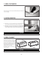
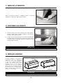
Attach the transition to insert top. Use metal foil duct tape to make all joints
secure and airtight.
- 8 -
11. INSTALL THE TRANSITION
A. When there is access to the top of the hood, connect ductwork and
seal connections with duct tape after Step 13 Install the insert.
B. When there is no access to the top of the hood, carefully pull down
the metal duct through the custom hood base hole. Slide this duct
over the transition. Seal the connection with metal foil duct tape.
HD0092
13. INSTALL THE INSERT
Install the insert inside the custom hood
and secure to the frame by using the
6 no. 10 x 2" hex head screws (included).
Position insert rearward so 3½" notch
from step 6 is covered. Start with 2 front
screws on top, then 2 rear screws on top,
and finish with 2 on rear side.
(See figure at right for mounting screw
specific locations.)
HD0102
TOP
REAR
CAUTION
Take care not to kink ducting when installing insert (step 13).
CAUTION
Take care not to kink ducting or pinch electrical cable when installing insert.
HD0057
12. DUCTING CONNECTION

- 9 -
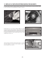
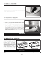
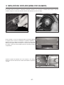
14. INSTALL THE INTERIOR BLOWER (P8D BLOWER MODEL ONLY)
The blower must be installed to the insert using 8 no. 8 x 3/8” screws. Remove the cover from the blower assembly. Remove the
impellers by pulling them out gently (see pictures below).
HD0021
HD0022
Install 4 no. 8 x 3/8” screws into the location as shown in the picture at
right. Do not tighten screws down fully, leave a 1/8” gap. Hang blower
unit onto insert inner top (screws through the large part of the keyhole).
Slide the blower to its position (screws in the small part of the keyhole).
Tighten the 4 screws.
Secure the blower by installing 4 more no. 8 x 3/8” screws into the
locations shown in the picture at right. Reinstall impellers and cover.
HD0081
HD0045

Connect wires as follow: ORANGE to ORANGE (B), WHITE to 2 other WHITE wires (C)
from step 10, and GREEN under ground screw (D). DO NOT FORGET TO CONNECT
THE GROUND. Reinstall the wiring box cover.
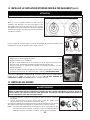
15. LIGHT BULBS
Both impellers are different in the dual blower, one rotates
clockwise and the other counterclockwise. Each wheel and
motor have an arrow and a number on them, you have to
match them correctly (see drawing at right).
21
HD0023
FRONT
HD0023
1
2
14. INSTALL THE INTERIOR BLOWER (P8D BLOWER MODEL ONLY) (CONT’D)
Pass the blower cable through the plastic clamp (A) in the wiring box. Completely tighten the
plastic clamp. See figure at right.
Connect blower cable into wiring box using provided waterproof wire connectors.
VO0084
Not completely
tightened
Completely
tightened
A
A
B
C
HE0033
WATERPROOF WIRE CONNECTORS INSTRUCTIONS:
1 Strip wires 3/8”.
2. Align frayed strands or conductors.
3. Do not pre-twist. Place stripped wires together with ends even, but lead smaller
stranded wires slightly ahead of larger solid or stranded wire.
4. Twist connector onto wires pushing firmly until hand-tight. DO NOT over torque.
5. When inserting wires into connectors, some sealant may leak out. Wipe off excess
sealant in and around conductors. DO NOT REUSE.
D
CAUTION
Make sure the impellers are correctly installed, the insert will not work properly if reversed.
This insert requires shielded halogen lamps (120 V, 50 W, MR16 or PAR16 with GU10 base), included.
1. Install the lamps by placing the bulb leads into their grooves in the socket.
2. Gently push upwards and turn clockwise until secure.
To remove lamps, gently push upwards and turn counterclockwise to disengage bulb
leads from their grooves.
NOTE: To ease removal of the bulbs, use a rubber dishwashing glove or use suction
cup tool available from Best. Contact Best Customer Service at 1-800-558-1711
to order suction cup tool, part no. 99526707.
12
HO0090
WARNING
Do not touch lamps during or soon after operation. Burns may occur. In order to prevent the risk of
personal injury, only install shielded halogen lamps. Also, never install a cool beam, a dichroic lamp, a
lamp not suitable for use in recessed luminaires or identified for use in enclosed fixtures.
!
- 10 -

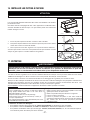
BAFFLE FILTERS AND IMPELLER(S).
The baffle filters, impeller(s) and grease rail should be cleaned frequently. Use a warm detergent solution. Baffle filters and
impeller(s) are dishwasher safe.
Remove baffle filters by pushing them towards the back of hood and rotating downward.
Clean all-metal filters in the dishwasher using a non-phosphate detergent. Discoloration of the filter may occur if using
phosphate detergent or as a result of local water conditions—but this will not affect filter performance. This discoloration is not
covered by the warranty.
Stainless steel cleaning
: How to maintain its “BRIGHT LOOK” and help prevent corrosion.
17. USE AND CARE
Avoid when choosing a detergent:
• Any cleaners that contain bleach will attack stainless steel.
• Any products containing : chloride, fluoride, iodide, bromide will deteriorate surfaces rapidly.
•Any combustible products used for cleaning such as acetone, alcohol, ether, benzol, etc., are highly explosive and
should never be used close to a range.
It is recommended to install side filters first and finish with center one.
A vertical arrow with the word AIR can be found on the filters border. Make sure to
install the baffle filters with the arrow pointing towards the inside of the hood insert.
See figure at right.
1. Insert upper end of baffle filter into the insert.
2. Raise lower end of baffle filter to position inside of unit and push to insert the
rear clip inside its slot in baffle back side.
3. While pushing the baffle filter, slide it under the inner retaining piece.
Make sure the baffle filters are positioned as shown at right in order to allow the
grease to reach the grease rail easily.
HO0021
Remove protective plastic film covering the baffle filters before installing them.
HD0090
3
2
1
16. INSTALL BAFFLE FILTERS
WARNING
Before servicing or cleaning the unit, switch power off at service panel and lock service panel to prevent
power from being switched on accidentally. When the service disconnecting means cannot be locked,
securely fasten a prominent warning device, such as a tag, to the service panel.
!
- 11 -
CAUTION
Do:
• Regularly wash with clean cloth or rag soaked with warm
water and mild soap or liquid dish detergent.
• Always clean in the direction of original polish lines.
• Always rinse well with clear water (2 or 3 times) after cleaning.
Wipe dry completely.
• You may also use a specialized household stainless steel
cleaner.
Do not:
• Use any steel or stainless steel wool or any other scrapers
to remove stubborn dirt.
• Use any harsh or abrasive cleansers.
• Allow dirt to accumulate.
• Let plaster dust or any other construction residues reach
the hood. During construction/renovation, cover the hood to
make sure no dust sticks to stainless steel surface.

- 12 -
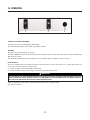
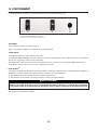
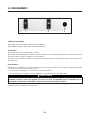
18. OPERATION
1) Light switch 2) Blower ON/OFF switch 3) Blower speed control
1 2
3
HC0014
The insert is operated using the (3) controls located beneath the front edge of the insert.
COOKTOP LIGHTING (HALOGEN)
The light switch turns the halogen lights ON and OFF.
Use shielded halogen bulbs (120 V, 50 W, type GU10), included.
BLOWER
The blower is operated using two (2) controls.
The blower ON/OFF switch turns the blower ON to the speed preset by the speed control. The blower must be turned ON and
OFF using this switch.
Turn the blower speed control counterclockwise to increase blower speed—clockwise to decrease speed.
HEAT SENTRY™
This unit is equipped with a Heat Sentry thermostat. This thermostat is a device that will turn on or speed up the blower if it
senses excessive heat above the cooking surface.
1) If blower is OFF—it turns blower ON to HIGH speed.
2) If blower is ON at a lower speed setting—it turns the blower up to HIGH speed.
When the temperature level drops to normal, the blower will return to its original setting.
Test all insert switches.
WARNING
The Heat Sentry can start the blower during a range top fire or other excessive heat situations even if the
hood is turned off. If this situation occurs, it is impossible to turn the blower OFF with blower switch. If
you must stop the blower, do it from the main electrical panel.
!

- 13 -
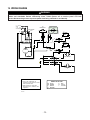
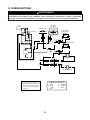
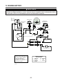
19. WIRING DIAGRAM
WARNING
Risk of electric shock. Electrical wiring must be done by qualified personnel in accordance with all applicable
codes and standards. Before connecting wires, switch power off at service panel and lock
service disconnecting means to prevent power from being switched on accidentally.
!
LIGHT SOCKET
LIGHTS
SWITCH
FAN SWITCH
LIGHT SOCKET
Neutral
Line
W
W
W
Y
Y
W
BLOWER
Line
BLOWER
Neutral
BK
Y
HS
THERMOSTAT
W
W
BK
BK
BK
BK
BK
BNBN
SPEED CONTROL
BK
O
O
R
R
BK
BK
BK
W
W
BK
W
W
FIELD WIRING
BOX
W
W
W
W
M
O
O
W
BK
120 VAC
Supply
Ground
G
O
WIRING COLOR CODE
BK BLACK
G GREEN
BN BROWN
R RED
W WHITE
Y YELLOW
1. If any of the original wire, as
supplied, must be replaced, use the
same equivalent wire.
2. Field wiring must comply with
applicable codes, ordinances and
regulations.
HE0035A
NOTES
O
O ORANGE

- 14 -
WARRANTY
ONE-YEAR LIMITED WARRANTY FOR BEST PRODUCTS
Broan-NuTone LLC (Broan-NuTone) warrants to the original consumer purchaser of Best products that such
products will be free from defects in materials or workmanship for a period of one year from the date of original
purchase. THERE ARE NO OTHER WARRANTIES, EXPRESS OR IMPLIED, INCLUDING, BUT NOT LIMITED
TO, IMPLIED WARRANTIES OR MERCHANT ABILITY OR FITNESS FOR A PARTICULAR PURPOSE.
During this one-year period, Broan-NuTone will, at its option, repair or replace, without charge, any product or
part which is found to be defective under normal use and service.
THIS WARRANTY DOES NOT EXTEND TO FLUORESCENT LAMP STARTERS, TUBES, HALOGEN AND
INCANDESCENT BULBS, FUSES, FILTERS, DUCTS, ROOF CAPS, WALL CAPS AND OTHER ACCESSORIES
FOR DUCTING. This warranty does not cover (a) normal maintenance and service or (b) any products or parts
which have been subject to misuse, negligence, accident, improper maintenance or repair (other than by
Broan-NuTone), faulty installation or installation contrary to recommended installation instructions.
The duration of any implied warranty is limited to the one-year period as specified for the express warranty.
Some states or provinces do not allow limitation on how long an implied warranty lasts, so the above
limitation may not apply to you.
BROAN-NUTONE’S OBLIGATION TO REPAIR OR REPLACE, AT BROAN-NUTONE’S OPTION, SHALL BE
THE PURCHASER’S SOLE AND EXCLUSIVE REMEDY UNDER THIS WARRANTY. BROAN-NUTONE
SHALL NOT BE LIABLE FOR INCIDENTAL, CONSEQUENTIAL OR SPECIAL DAMAGES ARISING OUT
OF OR IN CONNECTION WITH PRODUCT USE OR PERFORMANCE. Some states or provinces do not
allow the exclusion or limitation of incidental or consequential damages, so the above limitation or
exclusion may not apply to you.
This warranty gives you specific legal rights, and you may also have other rights, which vary from state to state
or province to another. This warranty supersedes all prior warranties.
To qualify for warranty service, you must (a) notify Broan-NuTone at the address or telephone number stated
below, (b) give the model number and part identification and (c) describe the nature of any defect in the product
or part. At the time of requesting warranty service, you must present evidence of the original purchase date.
In USA - Best
®
, 926 W. State Street, Hartford, WI 53027 (800-558-1711)
In Canada - Best
®
, 550 Lemire Blvd., Drummondville, QC, Canada, J2C 7W9 (866-737-7770)
www.BestRangeHoods.com

HL0123
- 15 -
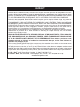
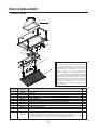
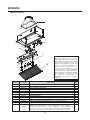
REPLACEMENT PARTS
REF. NO. PART NUMBER DESCRIPTION
QTY.
1 SV03428 TRANSITION 9” x 18” TO 10” ROUND 1
2 SV05869 BEST LOGO 1
3 SV06508 NYLON CONNECTOR KIT 2
4 SV15432 FILTER CLIP KIT 3
5 SV06364 POTENTIOMETER 1
6 SV06497 THERMOSTAT 1
7 SV16765 LAMP SHELL, SOCKET & TRIM ASSEMBLY (OUTDOOR) 2
8 SV03504 BLOWER SPEED CONTROL KNOB 1
9 SV06496 BLOWER SWITCH 1
10 SV06495 LIGHT SWITCH 1
11 SV05921 SHIELDED HALOGEN BULBS 120 V, 50 W, GU10 2
12 SV15422 BEST BAFFLE FILTERS 9.25’’ x 12.5’’ 3
SV04216
PARTS BAG INCLUDING: 3 WATERPROOF WIRE CONNECTORS, 6 NO. 10 X 2" HEX HEAD SCREWS,
2 WIRE CLAMPS LP16-AP, 8 NO. 8 X 3/8" STAINLESS STEEL SCREWS. 2 NO. 8 X 5/8" SCREWS,
4 NO. 10 X 2" FLAT HEAD SCREWS, 2 WALL ANCHORS, 6 WASHERS 3/16" ID X 3/4" OD,
4 STAINLESS STEEL 10-32 LOCKNUTS, 2 NO. 8 X 3/8" ZINC-PLATED SCREWS.
1
2
3
1
6
5
12
7
10
9
4
PIK33D MODEL
8
11
REPLACEMENT PARTS AND REPAIRS
In order to ensure your unit remains in good working
condition, you must use Broan-NuTone genuine
replacement parts only. Broan-NuTone genuine
replacement parts are specially designed for each
unit and are manufactured to comply with all the
applicable certification standards and maintain a high
standard of safety. Any third party replacement part
used may cause serious damage and drastically
reduce the performance level of your unit, which will
result in premature failing. Broan-NuTone recommends
to contact a certified service depot for all replacement
parts and repairs.

L0051
2
3
1
16
15
13
6
9
10
11
12
14
4
5
- 16 -
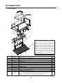
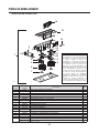
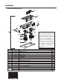
REPLACEMENT PARTS
DUAL BLOWER P8D
7
8
REF. NO. PART NUMBER DESCRIPTION
QTY.
1 P8D DUAL BLOWER ASSEMBLY 1
2 SV02160 CAPACITOR 15 µF 2
3
*
LOCK NUT NO. 6-32 1
4 SV01857 WIRE COVER 2
5 SV06338 MOTOR 165W CW 1
6 SV03400 BLOWER IMPELLER, HOOD 7.094” X 3.375” CW 1
7 SV01810 IMPELLER RING 2
8 SV03399 BLOWER IMPELLER, HOOD 7.094” X 3.375” CCW 1
9 SV06339 MOTOR 165 W CCW 1
10
*
WASHER 3/16” ID X 3/4” OD 6
11 SV11705 MOTOR MOUNT 2
12 SV02001 MOTOR GROMMET G-431-1 6
13 SV01927 METRIC SCREW M4 X 6 MM PAN QDRX 8
14 SV06369 BLOWER POWER CORD 1
15 SV15443 P8D ROUGH-IN PLATE 1
16 SV03500 AIR DEFLECTOR 1
*
8” TIE WRAP 2
SV11614 WIRE NO. 18 TEW BROWN X 10” 2
* STANDARD HARDWARE - MAY BE PURCHASED LOCALLY.
REPLACEMENT PARTS AND REPAIRS
In order to ensure your unit remains in good
working condition, you must use
Broan-NuTone genuine replacement parts
only. Broan-NuTone genuine replacement
parts are specially designed for each unit
and are manufactured to comply with all the
applicable certification standards and
maintain a high standard of safety. Any third
party replacement part used may cause
serious damage and drastically reduce the
performance level of your unit, which will
result in premature failing. Broan-NuTone
recommends to contact a certified service
depot for all replacement parts and repairs.

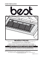
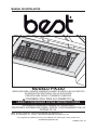
GUIDE D’INSTALLATION
BEST; Hartford, Wisconsin www.BestRangeHoods.com 800 558-1711
BEST; Drummondville, QC, Canada www.BestRangeHoods.com 866 737-7770
Pour enregistrer votre produit en ligne ou pour plus d’information, consultez notre site
www.BestRangeHoods.com
SV06322 Rév. 10
CONÇU POUR LA CUISSON DOMESTIQUE SEULEMENT
INSTALLATEUR : LAISSER CE GUIDE AU PROPRIÉTAIRE.
PROPRIÉTAIRE : DIRECTIVES D’UTILISATION ET D’ENTRETIEN EN PAGES 27 ET 28.
LIRE ET CONSERVER CES DIRECTIVES
!
!
HB0034
MODÈLE PIK33D
CONVIENT À UNE UTILISATION DANS DES LIEUX HUMIDES LORSQUE RACCORDÉ À UN
DISJONCTEUR DE FUITE À LA TERRE (DDFT).
C
ONÇU POUR FONCTIONNER SUR UN PATIO COUVERT OU DANS UNE VÉRANDA.

- 18 -
AVERTISSEMENT
AVERTISSEMENT
AFIN DE RÉDUIRE LES RISQUES D’INCENDIE,
D’ÉLECTROCUTION OU DE BLESSURES CORPORELLES,
SUIVEZ LES DIRECTIVES SUIVANTES :
1. N’utilisez cet appareil que de la façon prévue par le
manufacturier. Si vous avez des questions, contactez
le manufacturier à l’adresse et au numéro de
téléphone indiqués dans la garantie.
2. Avant de réparer ou de nettoyer l’appareil, couper
l’alimentation électrique en verrouillant le panneau de
distribution afin d’éviter sa remise en marche accidentelle.
Si le panneau de distribution ne peut être verrouillé, y
fixer un avertissement en évidence, telle qu’une
étiquette de couleur vive.
3. Les travaux d’installation et de raccordement électrique
doivent être effectués par une personne qualifiée,
conformément aux codes et aux standards de
construction, incluant ceux concernant la protection
contre les incendies.
4. Une quantité d’air adéquate est requise afin d’assurer
une bonne combustion et l’évacuation des gaz par la
cheminée dans le cas des équipements alimentés au
gaz afin de prévenir les retours de cheminée.
Conformez-vous aux instructions et aux standards de
sécurité des manufacturiers d’équipement de
chauffage, tel qu’ils sont publiés par la
National Fire
Protection Association
(NFPA) et l’
American Society
for Heating, Refrigeration and Air Conditioning
Engineers
(ASHRAE) ainsi que les responsables des
codes locaux.
5. Lorsque vous coupez ou perforez un mur ou un
plafond, prenez garde de ne pas endommager les fils
électriques ou autre installation qui pourraient y
être dissimulés.
6. Les ventilateurs avec conduits doivent toujours évacuer
l’air à l’extérieur.
7. Ne pas utiliser cet appareil avec une commande de
vitesse à semi-conducteur additionnelle.
8. Afin de réduire les risques d’incendie, n’utilisez que
des conduits en métal.
9. Cet appareil doit être mis à la terre et protégé par un
DDFT (disjoncteur de fuite à la terre).
10. Convient à une utilisation dans des lieux humides
seulement lorsqu’elle est raccordée à un
DISJONCTEUR DE FUITE À LA TERRE (DDFT).
11. Lorsqu’une réglementation est en vigueur localement
et qu’elle comporte des exigences d’installation et/ou
de certification plus restrictives, lesdites exigences
prévalent sur celles de ce document et l’installateur
entend s’y conformer à ses frais.
AFIN DE RÉDUIRE LES RISQUES DE FEU
DE CUISINIÈRE :
a) Ne jamais laisser les appareils de cuisson sans
surveillance lorsqu’ils sont réglés à feu vif. Les
débordements engendrent de la fumée et des
déversements graisseux pouvant s’enflammer.
Chauffez l’huile lentement, à feu doux ou moyen.
b) Toujours mettre la hotte en marche lorsque vous
cuisinez à feu vif ou que vous cuisinez des mets
flambés (par ex. : crêpes Suzette, cerises jubilé, steaks
au poivre flambés).
c) Nettoyez régulièrement la (les) roue(s) du ventilateur.
Ne laissez pas la graisse s’accumuler sur le ventilateur,
les filtres ou les conduits d’évacuation.
d) Utilisez le bon format de casserole. Servez-vous
toujours de casseroles et d’ustensiles appropriés à la
dimension de la surface chauffante.
AFIN D’ÉVITER TOUT RISQUE DE BLESSURES LORS
D’UN FEU DE CUISINIÈRE, SUIVEZ CES DIRECTIVES* :
1. Étouffez les flammes avec un couvercle hermétique,
une tôle à biscuits ou un plateau métallique et ensuite,
éteindre le brûleur. PRENEZ SOIN D’ÉVITER LES
BRÛLURES. SI LES FLAMMES NE S’ÉTEIGNENT
PAS IMMÉDIATEMENT, ÉVACUEZ LES LIEUX ET
APPELEZ LES POMPIERS.
2. NE PRENEZ JAMAIS UNE CASSEROLE EN
FLAMMES DANS VOS MAINS, vous pourriez subir
des brûlures.
3. N’UTILISEZ PAS D’EAU, incluant un linge à vaisselle
ou une serviette mouillée, cela pourrait occasionner
une violente explosion de vapeur.
4. N’utilisez un extincteur QUE DANS LE CAS OÙ :
A. Vous savez qu’il s’agit d’un extincteur de classe
ABC et que vous en connaissez le fonctionnement.
B. L’incendie est petit et limité à l’endroit où il a débuté.
C. Les pompiers ont été avisés.
D. Vous pouvez combattre l’incendie en ayant accès à
une sortie de secours.
*Tirées du
Kitchen Fire Safety Tips
publié par la NFPA.
ATTENTION
1. Pour usage domestique seulement. Ne pas utiliser
pour évacuer des vapeurs ou des matières
dangereuses ou explosives.
2. Afin d’éviter tout dommage au moteur et de
débalancer ou de rendre bruyante la roue du moteur,
garder votre appareil à l’abri des poussières de gypse
et de construction/rénovation, etc.
3. Le moteur de votre module de hotte encastrable
possède une protection thermique qui éteindra
automatiquement le moteur s’il devient surchauffé. Le
moteur repartira automatiquement une fois refroidi. Si
le moteur continue à arrêter et à repartir, faites-le vérifier.
4. La distance minimale entre le bas de votre hotte et la
surface de cuisson ne doit pas être inférieure à 36 po.
Un maximum de 42 po au-dessus de la surface de
cuisson est fortement recommandé pour une meilleure
évacuation des odeurs de cuisson.
5. Vu la grande dimension et le poids de cette hotte, il est
recommandé de confier son installation à 2 personnes.
6. Afin de réduire les risques d’incendie, assurez-vous
d’évacuer l’air à l’extérieur. Ne pas évacuer l’air dans
des espaces restreints comme l’intérieur des murs ou
plafond ou dans le grenier, faux plafond ou garage.
7. Cet appareil est équipé d’un thermostat pouvant faire
démarrer le ventilateur automatiquement. Afin de
réduire les risques de blessures, couper le courant à
partir du panneau de distribution et verrouiller ou
apposer un avertissement sur le panneau afin de
prévenir que la hotte soit mise en marche automatiquement.
8. Afin de réduire les risques d’incendie et d’électrocution,
le modèle PIK33D doit être installé uniquement avec
l’un des ventilateurs interne P8D ou avec le ventilateur
externe EB12 ou EB15 ou le ventilateur en ligne ILB11
(vendu séparément). Aucun autre ventilateur ne doit
être utilisé.
9. Lorsqu’il est utilisé comme appareil de démonstration,
ce module de hotte encastrable ne doit être utilisé
qu’avec un ensemble de cordon d’alimentation approuvé.
10. Veuillez consulter l’autocollant apposé à l’intérieur du
produit pour plus d’information ou autres exigences.
!
!

HL0080
- 19 -
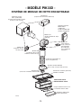
Transition modèle SV03428
(9 po x 18 po à 10 po ronde) (incluse)
Plaque ventilateur incluse avec
le ventilateur intérieur P8D
MODULE DE HOTTE
ENCASTRABLE PIK33D
- MODÈLE PIK33D -
SYSTÈME DE MODULE DE HOTTE ENCASTRABLE
Déviateur d’air
(inclus avec ventilateur intérieur P8D)
Revêtement d’armoire (optionnel)
L3336D ou L3348D
Ventilateur en ligne
ILB11 (1100 PCM)
(incluant deux transitions rondes
de 8 po x 12 po à 10 po)
Modèle 441
(Capuchon de mur
de 10 po rond)
Modèle 437
(Capuchon de toit à haut rendement)
Ventilateur extérieur
Modèle EB12
(1200 PCM)
ou EB15 (1500 PCM)
(vendus séparément)
Conduit de métal flexible de
10 po rond (optionnel)
Ventilateur double P8D
(vendu séparément)
Modèle 421
(Volet intérieur
10 po, rond vert.)
(Recommandé
pour utilisation
avec ventilateurs
extérieurs)
Modèle 410
(Conduit de 10 po rond
standard, sections de 2 pi)
Modèle 418
(Coude ajustable de 10 po,
optionnel)

- 20 -
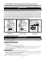
1. SÉLECTIONNER L’OPTION VENTILATEUR ET INSTALLER LES CONDUITS
Le module de hotte encastrable PIK33D doit être installé uniquement avec le ventilateur intérieur P8D, le ventilateur extérieur
EB12 ou EB15 ou le ventilateur en ligne ILB11 (vendus séparément). Aucun autre ventilateur ne peut être utilisé.
Si un ventilateur en ligne est installé, se reporter aux directives incluses avec celui-ci et suivre les étapes 1 à 6, 10 à 13, 15 et plus de ce guide.
Déterminer à quel endroit et de quelle façon les conduits seront installés. Il est préférable de garder un accès au-dessus du
module pour le raccordement des conduits. Sinon, des conduits de métal flexibles peuvent être utilisés. Installer des conduits
de 10 po en métal, coude(s) et capuchon de mur ou de toit selon le type de ventilateur. Utiliser des conduits circulaires avec
une petite section de conduit de métal flexible (environ 4 pi étiré) (optionnel) pour le raccordement à la transition. Utiliser des
vis pour fixer le conduit de métal flexible au conduit rigide. Utiliser du ruban adhésif de métal pour assurer l’étanchéité des joints.
La distance minimale entre le bas de votre hotte et la surface de cuisson ne doit pas être inférieure à 36 po. Un maximum
de 42 po au-dessus de la surface de cuisson est fortement recommandé pour une meilleure évacuation des odeurs de cuisson.
Une distance de plus de 42 po demeure à la discrétion de l’installateur et de l’utilisateur.
2. PRÉPARER L’INSTALLATION
NOTE : Avant de commencer l'installation, vérifier le contenu de la boîte. Si des pièces sont manquantes ou endommagées,
contacter le manufacturier.
S’assurer que les articles suivants soient inclus
:
- Module de hotte encastrable
- Accessoires :
• Transition (9 po x 18 po à 10 po ronde)
• 3 filtres à chicane
• 2 ampoules halogènes avec écran (120 V, 50 W, Type GU10)
• Sac de pièces incluant : 3 capuchons de connexion étanches, 6 vis à tête hexagonale n° 10 x 2 po, 2 serre-fils LP16-AP,
8 vis en acier inoxydable n° 8 x 3/8 po.
Inclus dans le sac de pièces, mais à ne pas utiliser (svp jeter) : 2 vis n° 8 x 5/8 po, 4 vis à tête fraisée n° 10 x 2 po,
2 douilles à expansion, 6 rondelles de 3/16 po DI x 3/4 po DE, 4 contre-écrous 10-32 en acier inoxydable,
2 vis n° 8 x 3/8 po plaquées zinc.
Pièces vendues séparément
:
- Ventilateur intérieur, modèle P8D avec plaque ventilateur et déviateur d’air
- Ensemble ventilateur extérieur, modèle EB12 ou EB15 (ne pas utiliser la plaque ventilateur incluse avec le ventilateur extérieur)
- Ensemble ventilateur en ligne, modèle ILB11 (incluant la plaque ventilateur et 2 transitions, ne pas utiliser la plaque ventilateur)
- Revêtement d’armoire, modèle L3336D ou L3348D (optionnel)
- Conduits (rigides et flexibles), coudes, volets, capuchons de mur ou de toit. Consulter la page 19 pour la liste complète des
accessoires de ventilation et des numéros de modèle.
NOTE : Lors de l’installation, protéger le plan de cuisson et/ou le comptoir de cuisine.
Module avec
ventilateur
intérieur
Capuchon
de toit
Capuchon
de mur
HH0005F
Conduit rond de
10 po avec conduit
de métal flexible
de 10 po rond (opt.)
Transition ronde
de 9 po x 18 po
à 10 po
Minimum de 36 po
au-dessus de la
surface de cuisson
Module
Ventilateur
extérieur
HH0042F
Conduit rond de
10 po avec conduit
de métal flexible de
10 po rond (opt.)
Transition de
9 po x 18 po à
10 po
Minimum de 36 po
au-dessus de la
surface de cuisson
Ventilateur en ligne
Conduit rond
de 10 po
HH0067F
Capuchon de toit
Capuchon
de mur
Module
Minimum de 36 po
au-dessus de la
surface de cuisson
Conduit métal flex.
de10 po
rond (opt.)
INSTALLATION TYPIQUE
VENTILATEUR INTÉRIEUR
MODÈLE
P8D
I
NSTALLATION TYPIQUE
VENTILATEUR EXTÉRIEUR
MODÈLES
EB12 OU EB15
INSTALLATION TYPIQUE
VENTILATEUR EN LIGNE
MODÈLE
ILB11
AVERTISSEMENT
Il est recommandé de porter des lunettes et des gants de sécurité lors de l’installation, de l’entretien ou
de la réparation de cet appareil.
Ce module de hotte encastrable a été conçu pour fonctionner avec une cuisinière extérieure électrique ou au gaz, lorsqu’elle est utilisée
sur un patio couvert ou une véranda. Comme tous les électroménagers, cet appareil doit être à l’abri des intempéries.
AVERTISSEMENT
Cet appareil n’est pas conçu pour être utilisé avec un barbecue au charbon de bois.
0
!
!
La page est en cours de chargement...
La page est en cours de chargement...
La page est en cours de chargement...
La page est en cours de chargement...
La page est en cours de chargement...
La page est en cours de chargement...
La page est en cours de chargement...
La page est en cours de chargement...
La page est en cours de chargement...
La page est en cours de chargement...
La page est en cours de chargement...
La page est en cours de chargement...
La page est en cours de chargement...
La page est en cours de chargement...
La page est en cours de chargement...
La page est en cours de chargement...
La page est en cours de chargement...
La page est en cours de chargement...
La page est en cours de chargement...
La page est en cours de chargement...
La page est en cours de chargement...
La page est en cours de chargement...
La page est en cours de chargement...
La page est en cours de chargement...
La page est en cours de chargement...
La page est en cours de chargement...
La page est en cours de chargement...
La page est en cours de chargement...
-
 1
1
-
 2
2
-
 3
3
-
 4
4
-
 5
5
-
 6
6
-
 7
7
-
 8
8
-
 9
9
-
 10
10
-
 11
11
-
 12
12
-
 13
13
-
 14
14
-
 15
15
-
 16
16
-
 17
17
-
 18
18
-
 19
19
-
 20
20
-
 21
21
-
 22
22
-
 23
23
-
 24
24
-
 25
25
-
 26
26
-
 27
27
-
 28
28
-
 29
29
-
 30
30
-
 31
31
-
 32
32
-
 33
33
-
 34
34
-
 35
35
-
 36
36
-
 37
37
-
 38
38
-
 39
39
-
 40
40
-
 41
41
-
 42
42
-
 43
43
-
 44
44
-
 45
45
-
 46
46
-
 47
47
-
 48
48


Best PIK33 Guide d'installation
- Catégorie
- Hottes
- Taper
- Guide d'installation
dans d''autres langues
- English: Best PIK33 Installation guide
- español: Best PIK33 Guía de instalación
