
Model Name: BRFMS
Type of product: Battery Radiofrequency Module
Brand Name: Visteon
Manufacturer: Visteon Corporation
Manufacturer Address: One Village center drive, Van Buren Township
48111-5711 Michigan
United States of America
BRFM features:
The BRFM is an electronic module intended to aggregate data from up to 24 CMU units and module
temperatures from the High Voltage battery bus in addition to pack voltage and current data collected
form the Battery Disconnect Signal Board (BDSB) and from multiple Cell Monitoring Units (CMUs) to
communicate them to the Vehicle Integration Control Module (VICM3).
All cell voltages, module temperatures, pack voltage and current are reported directly to the VICM3 on a
regular periodic basis.
BRFM Single variant has a single wireless RFIC (Pinnacle) and one antenna.
The BRFM implements a Pinnacle IC (ADRF8850), this is an IC that provides wireless communication
between the Battery Cell Monitoring chip and the Battery Management System Controller.
The BRFM includes a voltage supervisor/windowed watchdog (TPS3850) counter which generates a
wake up signal to the VICM3 when any of the battery cells reports a critical condition when the VICM3
is sleeping.
The BRFM has two redundant sets of sensors that monitor the battery pack for excessive temperature,
pressure, or hydrogen concentration that indicate a battery cell thermal runaway or thermal propagation.
System interaction:
Module-to-Vehicle Electrical Interface
Analog Input
VICM3 provides power to BRFM module. Power nominal value is 5.4V Minimum voltage expected is 5.2V and maximum
is 5.6V.
Analog Output
BDSB Power Output is provided or enabled by BRFM module depending on variant. BDSB Power is provided by Single
BRFM variant. BDSB Power nominal value is 5V. Minimum voltage expected is 4.2V and maximum is 5.5V
Digital (discrete
state) Output
BDSB Power Output is provided or enabled by BRFM module depending on variant. BDSB Power is enabled by sending
commands through the Dual BRFM variant. BDSB Power nominal value is 5V. Minimum voltage expected is 4.2V and
maximum is 5.5V
Communication
Bus
isoSPI communication serves as interface between BRFM and VICM3, as well as BRFM and BDSB. isoSPI lines shall be
monitored to ensure proper performance. Amplitude and timing measurements should be captured. 1Mbps nominal is
expected.
RF Link(s)
ISM Band (2.4GHz to 2.5GHz) used to communicate with CMU modules. Rx sensitivity shall be around 50% of PER,
where each measurement shall vary by no more than +/- 2.0dB from the golden sample. Tx output power shall vary by no
more than +/-2.5dB from the golden sample. Radio frequency reference shall be within ± 20PPM from desired frequency
(2.44GHz, channel 7).
Module-to-Vehicle Non-Electrical Interface
Pressure Sensors -> Values shall be between 50kPa and 150kPa ± 1% (0 – 150C) and ±2% (-40C – 0C)
Hydrogen Sensors -> Values shall be between 0PPM and 65,000PPM ± 100PPM (5% of accuracy)
Temperature Sensors -> Detection range shall be between -40C and 150C ± 1% of measured value
Internal Interface
Note: For these internal I/O, monitoring shall only occur via communication bus data or via indirect methods. Direct monitoring using
attachments leads to external monitoring devices shall not be included.
Switching &
Clock
SPI communication shall be 1Mbps nominal. Used to communicate between RF manager to Sensors ASIC and RF
Manager to isoSPI Transceiver.

Frequency
Content
RF Manager IC XTAL frequency shall be 40MHz nominal.
Pressure sensor frequency shall be 20kHz.
Hydrogen sensor frequency shall be 24.5kHz.
UART communication between RF Manager 1 and RF Manager 2 for Dual BRFM variant. These shall be 1Mbps
nominal.
Analog Output
3.3V voltage output from U7/U9 shall be within the following range: +3.25V < VOUT < +3.35V
Main power supply (U30001) shall have an output voltage of 3.3V with ±5mV peak-to-peak ripple voltage
Digital (discrete
state) Output
Communication
Bus
Note: This section assumes that production software is not mandatory; the use of specialized software is acceptable.
Note: Software diagnostic timers should be reset to minimum detection values, to facilitate assertion of potential diagnostic flags
during the RF exposure time (maximum 2 seconds).
Note: States/faults/issues shall be reported directly over the communication bus (i.e., Class 2, Controller Area Network (CAN),
etc.) or indirectly if the communication bus is not available via the cycling of output(s) (e.g., PWM duty cycle change, telltale flash
rate change, etc.)
Note: Unless otherwise specified in the EMC Test Plan, in order to ensure a refreshed value, all information related to data
monitoring (such as analog input voltages, operating states, etc.) shall be via parameter requests (e.g., Parameter ID (PID)) and
not via scheduled, or periodic, broadcast messages. This ensures bi-directional communications during immunity testing.
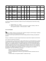
Harness Pinout, Capacities, and Use
Connecto
r ID /
Cavity #
Name
Description
Wire
Gauge
(AWG)
Used in
Vehicle
Twist
w/
Cavity
#
Shield
ed w/
Cavity
#
Applicable Bands
Termination
(R-L-C) etc.
Required for Module
Operation
External
Antenna
Band
WiFi
External
Antenna
Band
YYYY
X1-1
BUF5V
I
5V Input Power
from VICM
16
n/a
n/a
Yes
n/a
n/a
X1-2
NC
NC
n/a
n/a
n/a
n/a
n/a
n/a
X1-3
NC
NC
n/a
n/a
n/a
n/a
n/a
n/a
X1-4
VICM_
WU_SI
G
Vehicle Integration
Control Module
Wake Up Signal
Connect to
5V
16
n/a
n/a
Yes
n/a
n/a
X1-5
BUF5V
O
5V Output Power
to BDSB
BDSB or
simulator
16
n/a
n/a
Yes
n/a
n/a
X1-6
NC
NC
n/a
n/a
n/a
n/a
n/a
n/a
X1-7
RTN_5
VO
Ground to BDSB
16
n/a
n/a
Yes
n/a
n/a
X1-8
RTN_5
VI
Ground to VICM
16
n/a
n/a
Yes
n/a
n/a
X1-9
BRFM_
SPLY_
V_2
Battery Radio
Frequency Module
Supply Voltage 2
16
n/a
n/a
Yes
n/a
n/a
X1-10
NC
NC
n/a
n/a
n/a
n/a
n/a
n/a
X1-11
ISOSPI
_PV2
isoSPI Positive 2 to
VICM
100 ohm
cross
positive and
negative
20
n/a
n/a
Yes
n/a
n/a
X1-12
ISOSPI
_NV2
isoSPI Negative 2
to VICM
X1-13
ISOSPI
_PV1
isoSPI Positive 1 to
VICM
100 ohm
cross
positive and
negative
20
n/a
n/a
Yes
n/a
n/a

X1-14
ISOSPI
_NV1
isoSPI Negative 1
to VICM
X1-15
ISOSPI
_PB1
isoSPI Positive 1 to
BDSB 1
100 ohm
cross
positive and
negative
20
n/a
n/a
Yes
n/a
n/a
X1-16
ISOSPI
_NB1
isoSPI Negative 1
to BDSB 1
X1-17
ISOSPI
_PB2
isoSPI Positive 2 to
BDSB 2
100 ohm
cross
positive and
negative
20
n/a
n/a
Yes
n/a
n/a
X1-18
ISOSPI
_NB2
IsoSPI Negative 2
to BDSB 2
X1-19
NC
NC
n/a
n/a
n/a
n/a
n/a
n/a
X1-20
BRFM_
RTN_2
Battery Radio
Frequency Module
Return 2
BDSB or
simulation
16
n/a
n/a
Yes
n/a
n/a
The following information shall also be included in the case of radio equipment intentionally emitting
radio waves:
a. Frequency band : 2.4 – 2.5 GHz
b. Maximum radio-frequency power transmitted in the frequency band(s) in which the
radio equipment operates. Max output power = 10dBM
(U.S.A. and Canada)
FCC
This device complies with Part 15 of the FCC Rules. Operation is subject to the following two conditions:
(1) This device may not cause harmful interference, and
(2) The device must accept any interference received, including interference that may cause undesired
operation.
Changes or modifications not expressly approved by the party responsible for compliance could void the
user’s authority to operate the equipment.
This equipment has been tested and found to comply with the limits for a Class B digital device, pursuant
to part 15 of the FCC Rules. These limits are designed to provide reasonable protection against harmful
interference in a residential installation. This equipment generates, uses and can radiate radio frequency
energy and, if not installed and used in accordance with the instructions, may cause harmful interference
to radio communications. However, there is no guarantee that interference will not occur in a particular
installation. If this equipment does cause harmful interference to radio or television reception, which can
be determined by turning the equipment off and on, the user is encouraged to try to correct the
interference by one or more of the following measures:
- Reorient or relocate the receiving antenna.
- Increase the separation between the equipment and receiver.
- Connect the equipment into an outlet on a circuit different from that to which the receiver is
connected.
- Consult the dealer or an experienced radio/TV technician for help.

RF exposure safety
This device complies with the FCC RF exposure limits and has been evaluated in compliance with
portable exposure conditions.
The equipment must be installed and operated and was evaluated with minimum distance of 11 cm of
the human body. This distance or greater is maintained by vehicle design and ensures compliance by
normal use of the vehicle.
ISED CANADA
This device complies with Industry Canada License-exempt RSS standard(s). Operation is subject to the
following two conditions:
(1) This device may not cause harmful interference, and
(2) The device must accept any interference received, including interference that may cause undesired
operation.
Le présent appareil est conforme aux CNR d'Industrie Canada applicables aux appareils radio exempts de
licence.L'exploitation est autorisée aux deux conditions suivantes:
(1) l'appareil ne doit pas produire de brouillage, et,
(2) l'utilisateur de l'appareil doit accepter tout brouillage radioélectrique subi, même si le brouillage est
susceptible d'en compromettre le fonctionnement.
Changes or modifications not expressly approved by the party responsible for compliance could void the
user’s authority to operate the equipment.
RF exposure safety
This device complies with ISED RF exposure limits and has been evaluated in compliance with portable
exposure conditions.
The equipment must be installed and operated and was evaluated with minimum distance of 11 cm of
the human body. This distance or greater is maintained by vehicle design and ensures compliance by
normal use of the vehicle.
CAN ICES-003
Les changements ou modifications non expressément approuvés par la partie responsable de la
conformité peuvent annuler le droit de l'utilisateur à utiliser l'équipement.
Sécurité d'exposition aux RF
Cet appareil est conforme aux limites d'exposition RF d'ISDE et a été évalué conformément aux
conditions d'exposition portable.
L'équipement doit être installé et utilisé à une distance minimale de 11 cm du corps humain.
CAN NMB-003
Cet appareil numérique de classe B est conforme à la norme canadienne NMB-003.

-
 1
1
-
 2
2
-
 3
3
-
 4
4
-
 5
5


dans d''autres langues
- English: VISTEON BRFMS Operating instructions
Documents connexes
Autres documents
-
Multitech MTQ-LSP3-B02 Mode d'emploi
-
Multitech MTQ-MNA1-B01-SP Mode d'emploi
-
-
-
 WiSilica WIM1481 Manuel utilisateur
-
Eurotech DynaGATE 10-12 Le manuel du propriétaire
-
-
-
-
