Hitachi DS14DVF3 Safety Instructions And Instruction Manual
- Catégorie
- Outils électroportatifs
- Taper
- Safety Instructions And Instruction Manual

INSTRUCTIONS DE SECURITE ET MODE D’EMPLOI
AVERTISSEMENT
Une utilisation INCORRECTE OU DANGEREUSE de cet outil motorisé peut entraîner
la mort ou de sérieuses blessures corporelles!
Ce mode d’emploi contient d’importantes informations à propos de la sécurité de
ce produit. Prière de lire et de comprendre ce mode d’emploi AVANT d’utiliser
l’outil motorisé. Garder ce mode d’emploi à la disponibilité des autres utilisateurs
et propriétaires avant qu’ils utilisent l’outil motorisé. Ce mode d’emploi doit être
conservé dans un endroit sûr.
SAFETY INSTRUCTIONS AND INSTRUCTION MANUAL
WARNING
IMPROPER OR UNSAFE use of this power tool can result in death or serious bodily
injury!
This manual contains important information about product safety. Please read
and understand this manual BEFORE operating the power tool. Please keep this
manual available for other users and owners before they use the power tool. This
manual should be stored in safe place.
INSTRUCCIONES DE SEGURIDAD Y MANUAL DE INSTRUCCIONES
ADVERTENCIA
¡La utilización INAPROPIADA O PELIGROSA de esta herramienta eléctrica puede
resultar en lesiones de gravedad o la muerte!
Este manual contiene información importante sobre la seguridad del producto.
Lea y comprenda este manual ANTES de utilizar la herramienta eléctrica. Guarde
este manual para que puedan leerlo otras personas antes de utilizar la herramienta
eléctrica. Este manual debe ser guardado en un lugar seguro.
DS18DVF3
DS 12DVF3
•
DS 14DVF3
DS 18DVF3
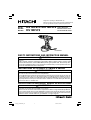
Model
Cordless Driver Drill
Modèle
Perceuse-visseuse sans fil
Modelo
Taladro atornillador a batería
Designed for operating in USA & Canada only.
When this product is used in areas other than the USA & Canada,
we cannot guarantee the product quality and performance.
01Eng_DS12DVF3_US 9/20/12, 12:231

CONTENTS
Page
ASSEMBLY AND OPERATION ............................... 12
APPLICATIONS ................................................... 12
REMOVAL AND INSTALLATION METHOD
OF BATTERY ................................................ 12
CHARGING METHOD ......................................... 12
BEFORE USE ....................................................... 13
OPERATION ......................................................... 13
THE SCOPE AND SUGGESTIONS
FOR USES .................................................... 18
HOW TO SELECT TIGHTENING TORQUE ......... 18
MAINTENANCE AND INSPECTION ....................... 19
TROUBLESHOOTING GUIDE ................................. 20
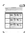
ACCESSORIES ......................................................... 21
STANDARD ACCESSORIES ............................... 21
OPTIONAL ACCESSORIES ................................. 22
PARTS LIST .............................................................. 61
TABLE DES MATIERES
Page
IMPORTANT INFORMATION ............................. 4
MEANINGS OF SIGNAL WORDS ...................... 4
SAFETY .................................................................... 4
GENERAL POWER TOOL SAFETY WARNINGS .. 4
SPECIFIC SAFETY RULES AND SYMBOLS ....... 6
IMPORTANT SAFETY INSTRUCTIONS
FOR BATTERY CHARGER ........................... 7
IMPORTANT SAFETY INSTRUCTIONS
FOR USE OF THE BATTERY AND
BATTERY CHARGER .................................... 7
DISPOSAL OF THE EXHAUSTED BATTERY ..... 8
FUNCTIONAL DESCRIPTION .................................. 9
MODEL ................................................................. 9
NAME OF PARTS ................................................ 9
SPECIFICATIONS ................................................ 11
English
Français
Page
INFORMATIONS IMPORTANTES DE SÉCURITÉ ..
23
SIGNIFICATION DES MOTS D’AVERTISSEMENT
.. 23
SÉCURITÉ ................................................................ 23
AVERTISSEMENTS DE SÉCURITÉ GÉNÉRAUX
CONCERNANT LES OUTILS ÉLECTRIQUES
....... 23
REGLES DE SÉCURITÉ SPÉCIFIQUES ET
SYMBOLES .................................................. 25
CONSIGNES DE SÉCURITÉ IMPORTANTES POUR LE
CHARGEUR DE BATTERIE
............................... 26
CONSIGNES DE SÉCURITÉ IMPORTANTES POUR
L’UTILISATION DE LA BATTERIE ET DU
CHARGEUR DE BATTERIE
........................... 27
MISE AU REBUT D’UNE BATTERIE USÉE ........ 27
DESCRIPTION FONCTIONNELLE ........................... 28
MODÈLE .............................................................. 28
NOM DES PARTIES ............................................ 28
SPECIFICATIONS ................................................ 30
Page
ASSEMBLAGE ET FONCTIONNEMENT ................ 31
UTILISATIONS .................................................... 31
MÉTHODE DE RETRAIT ET D’INSTALLATION
DE LA BATTERIE .......................................... 31
MÉTHODE DE RECHARGE ................................. 31
AVANT L’UTILISATION ...................................... 32
UTILISATION ....................................................... 32
PLAGE D’UTILISATION ET SUGGESTIONS ..... 37
SÉLECTION DU COUPLE DE SERRAGE ............ 37
ENTRETIEN ET INSPECTION .................................. 38
GUIDE DE DÉPANNAGE ......................................... 39
ACCESOIRES ........................................................... 40
ACCESSOIRES STANDARD ............................... 40
ACCESSOIRES EN OPTION ................................ 41
LISTE DES PIECES ................................................... 61
HITACHI AUTHORIZED SERVICE CENTERS
Service under this warranty is available from Hitachi Koki U.S.A., Ltd. at:
IN THE U.S.A. IN CANADA
3950 Steve Reynolds Blvd. Norcross, GA 30093
450 Export Blvd. Unit B, Mississauga, ON L5T 2A4
9409 Owensmouth Ave. Chatsworth, CA 91311
OR CALL: (800) 829-4752 for a service center OR CALL: (800) 970-2299 for a service center
nearest you. nearest you.
CENTRES TECHNIQUES HITACHI AGREES
La réparation est réalisée dans le cadre de cette garantie par Hitachi Koki U.S.A., Ltd.:
AUX ETATS-UNIS AU CANADA
3950 Steve Reynolds Blvd. Norcross, GA 30093
450 Export Blvd. Unit B, Mississauga, ON L5T 2A4
9409 Owensmouth Ave. Chatsworth, CA 91311
OU APPELEZ LE: (800) 829-4752 pour connaître OU APPELEZ LE: (800) 970-2299 pour connaître
le centre technique le plus le centre technique le plus
proche de chez vous. proche de chez vous.
01Eng_DS12DVF3_US 4/9/13, 13:502

ÍNDICE
Español
Página
INFORMACIÓN IMPORTANTE SOBRE
SEGURIDAD ................................................. 42
SIGNIFICADO DE LAS PALABRAS DE
SEÑALIZACIÓN ............................................ 42
SEGURIDAD ............................................................. 42
ADVERTENCIAS DE SEGURIDAD GENERAL DE
LA HERRAMIENTA ELÉCTRICA .................. 42
NORMAS Y SÍMBOLOS ESPECÍFICOS DE
SEGURIDAD ................................................. 44
INSTRUCCIONES IMPORTANTES DE SEGURIDAD
PARA EL CARGADOR DE BATERÍAS
.......... 45
INSTRUCCIONES IMPORTANTES DE
SEGURIDAD PARA LA BATERÍA Y EL
CARGADOR DE BATERÍAS ......................... 46
ELIMINACIÓN LAS BATERÍAS AGOTADAS ..... 46
DESCRIPCIÓN FUNCIONAL .................................... 47
MODELO .............................................................. 47
NOMENCLATURA ............................................... 47
ESPECIFICACIONES ............................................ 49
Página
MONTAJE Y OPERACIÓN ...................................... 50
APLICACIONES ................................................... 50
MÉTODO DE EXTRACCIÓN E INSTALACIÓN
DE LA BATERÍA ............................................ 50
MÉTODO DE CARGA .......................................... 50
ANTES DE LA UTILIZACIÓN .............................. 51
OPERACIÓN ........................................................ 51
ALCANCE Y SUGERENCIAS PARA LA
UTILIZACIÓN ................................................ 56
FORMA DE SELECCIONAR EL PAR DE
APRIETE ........................................................ 56
MANTENIMIENTO E INSPECCIÓN ........................ 57
GUIA DE IDENTIFICACION DE PROBLEMAS ........ 58
ACCESORIOS ........................................................... 59
ACCESORIOS ESTÁNDAR ................................. 59
ACCESORIOS OPCIONALES .............................. 60
LISTA DE PIEZAS .................................................... 61
CENTROS DE SERVICIO AUTORIZADOS DE HITACHI
Hitachi Koki U.S.A., Ltd. proporciona un servicio de reparaciones bajo esta garantía en:
EN EE. UU. EN CANADA
3950 Steve Reynolds Blvd. Norcross, GA 30093
450 Export Blvd. Unit B, Mississauga, ON L5T 2A4
9409 Owensmouth Ave. Chatsworth, CA 91311
O LLAME AL: (800) 829-4752 para informarse O LLAME AL: (800) 970-2299 para informarse
del centro de reparaciones más del centro de reparaciones más
cercano. cercano.
01Eng_DS12DVF3_US 4/9/13, 13:503

English
4
IMPORTANT SAFETY INFORMATION
Read and understand all of the safety precautions, warnings and operating instructions in the Instruction Manual
before operating or maintaining this power tool.
Most accidents that result from power tool operation and maintenance are caused by the failure to observe basic
safety rules or precautions. An accident can often be avoided by recognizing a potentially hazardous situation
before it occurs, and by observing appropriate safety procedures.
Basic safety precautions are outlined in the “SAFETY” section of this Instruction Manual and in the sections which
contain the operation and maintenance instructions.
Hazards that must be avoided to prevent bodily injury or machine damage are identified by WARNINGS on the
power tool and in this Instruction Manual.
NEVER use this power tool in a manner that has not been specifically recommended by HITACHI.
MEANINGS OF SIGNAL WORDS
WARNING indicates a potentially hazardous situation which, if ignored, could result in death or serious injury.
CAUTION indicates a potentially hazardous situation which, if not avoided, may result in minor or moderate
injury, or may cause machine damage.
NOTE emphasizes essential information.
SAFETY
GENERAL POWER TOOL SAFETY WARNINGS
WARNING
Read all safety warnings and all instructions.
Failure to follow the warnings and instructions may result in electric shock, fire and/or serious injury.
Save all warnings and instructions for future reference.
The term “power tool” in the warnings refers to your mains-operated (corded) power tool or battery-operated
(cordless) power tool.
1) Work area safety
a) Keep work area clean and well lit.
Cluttered or dark areas invite accidents.
b) Do not operate power tools in explosive
atmospheres, such as in the presence of
flammable liquids, gases or dust.
Power tools create sparks which may ignite
the dust or fumes.
c) Keep children and bystanders away while
operating a power tool.
Distractions can cause you to lose control.
2) Electrical safety
a) Power tool plugs must match the outlet.
Never modify the plug in any way.
Do not use any adapter plugs with earthed
(grounded) power tools.
Unmodified plugs and matching outlets will
reduce risk of electric shock.
b) Avoid body contact with earthed or grounded
surfaces such as pipes, radiators, ranges and
refrigerators.
There is an increased risk of electric shock if
your body is earthed or grounded.
c) Do not expose power tools to rain or wet
conditions.
Water entering a power tool will increase the
risk of electric shock.
d) Do not abuse the cord. Never use the cord
for carrying, pulling or unplugging the power
tool.
Keep cord away from heat, oil, sharp edges
or moving parts.
Damaged or entangled cords increase the risk
of electric shock.
e) When operating a power tool outdoors, use
an extension cord suitable for outdoor use.
Use of a cord suitable for outdoor use reduces
the risk of electric shock.
f) If operating a power tool in a damp location
is unavoidable, use a residual current device
(RCD) protected supply.
Use of an RCD reduces the risk of electric
shock.
01Eng_DS12DVF3_US 4/9/13, 13:504

English
5
3) Personal safety
a) Stay alert, watch what you are doing and use
common sense when operating a power tool.
Do not use a power tool while you are tired
or under the influence of drugs, alcohol or
medication.
A moment of inattention while operating
power tools may result in serious personal
injury.
b) Use personal protective equipment. Always
wear eye protection.
Protective equipment such as dust mask, non-
skid safety shoes, hard hat, or hearing
protection used for appropriate conditions
will reduce personal injuries.
c) Prevent unintentional starting. Ensure the
switch is in the off-position before connecting
to power source and/or battery pack, picking
up or carrying the tool.
Carrying power tools with your finger on the
switch or energising power tools that have
the switch on invites accidents.
d) Remove any adjusting key or wrench before
turning the power tool on.
A wrench or a key left attached to a rotating
part of the power tool may result in personal
injury.
e) Do not overreach. Keep proper footing and
balance at all times.
This enables better control of the power tool
in unexpected situations.
f) Dress properly. Do not wear loose clothing
or jewellery. Keep your hair, clothing and
gloves away from moving parts.
Loose clothes, jewellery or long hair can be
caught in moving parts.
g) If devices are provided for the connection of
dust extraction and collection facilities,
ensure these are connected and properly
used.
Use of dust collection can reduce dust-related
hazards.
4) Power tool use and care
a) Do not force the power tool. Use the correct
power tool for your application.
The correct power tool will do the job better
and safer at the rate for which it was designed.
b) Do not use the power tool if the switch does
not turn it on and off.
Any power tool that cannot be controlled with
the switch is dangerous and must be repaired.
c) Disconnect the plug from the power source
and/or the battery pack from the power tool
before making any adjustments, changing
accessories, or storing power tools.
Such preventive safety measures reduce the
risk of starting the power tool accidentally.
d) Store idle power tools out of the reach of
children and do not allow persons unfamiliar
with the power tool or these instructions to
operate the power tool.
Power tools are dangerous in the hands of
untrained users.
e) Maintain power tools. Check for
misalignment or binding of moving parts,
breakage of parts and any other condition
that may affect the power tool’s operation.
If damaged, have the power tool repaired
before use.
Many accidents are caused by poorly
maintained power tools.
f) Keep cutting tools sharp and clean.
Properly maintained cutting tools with sharp
cutting edges are less likely to bind and are
easier to control.
g) Use the power tool, accessories and tool bits
etc. in accordance with these instructions,
taking into account the working conditions
and the work to be performed.
Use of the power tool for operations different
from those intended could result in a
hazardous situation.
5) Battery tool use and care
a) Recharge only with the charger specified by
the manufacturer.
A charger that is suitable for one type of
battery pack may create a risk of fire when
used with another battery pack.
b) Use power tools only with specifically
designated battery packs.
Use of any other battery packs may create a
risk of injury and fire.
c) When battery pack is not in use, keep it away
from other metal objects like paper clips,
coins, keys, nails, screws, or other small
metal objects, that can make a connection
from one terminal to another.
Shorting the battery terminals together may
cause burns or a fire.
d) Under abusive conditions, liquid may be
ejected from the battery; avoid contact. If
contact accidentally occurs, flush with water.
If liquid contacts eyes, additionally seek
medical help.
Liquid ejected from the battery may cause
irritation or burns.
6) Service
a) Have your power tool serviced by a qualified
repair person using only identical
replacement parts.
This will ensure that the safety of the power
tool is maintained.
–WARNING–
To reduce the risk of injury, user must read
instruction manual.
01Eng_DS12DVF3_US 4/9/13, 13:505

English
6
WARNING:
Some dust created by power sanding, sawing,
grinding, drilling, and other construction activities
contains chemicals known to the State of California
to cause cancer, birth defects or other reproductive
harm. Some examples of these chemicals are:
●
Lead from lead-based paints,
●
Crystalline silica from bricks and cement and other
masonry products, and
●
Arsenic and chromium from chemically-treated
lumber.
Your risk from these exposures varies, depending
on how often you do this type of work. To reduce
your exposure to these chemicals: work in a well
ventilated area, and work with approved safety
equipment, such as those dust masks that are
specially designed to filter out microscopic particles.
SPECIFIC SAFETY RULES AND SYMBOLS
1. Wear ear protectors when impact drilling.
Exposure to noise can cause hearing
loss.
2. Use auxiliary handle(s), if supplied with the tool.
Loss of control can cause personal injury.
3. Hold power tool by insulated gripping surfaces,
when performing an operation where the cutting
accessory may contact hidden wiring.
Cutting accessory contacting a “live” wire may
make exposed metal parts of the power tool “live”
and could give the operator an electric shock.
4. Hold power tool by insulated gripping surfaces,
when performing an operation where the fastener
may contact hidden wiring.
Fasteners contacting a “live” wire may make
exposed metal parts of the power tool “live” and
could give the operator an electric shock.
5. NEVER place hands or other body parts near the
drill bit or chuck during operation. Hold the drill
by its handle only.
6. Because the cordless driver drill operates by
battery power, be aware of the fact that it can begin
to operate at any time.
7. When working at elevated locations, clear the area
of all other people and be aware of conditions
below you.
8. NEVER touch moving parts.
NEVER place your hands, fingers or other body
parts near the tool’s moving parts.
9. NEVER operate without all guards in place.
NEVER operate this tool without all guards or
safety features in place and in proper working
order. If maintenance or servicing requires the
removal of a guard or safety feature, be sure to
replace the guard or safety feature before resuming
operation of the tool.
10. Use right tool.
Don’t force small tool or attachment to do the job
of a heavy-duty tool.
Don’t use tool for purpose not intended —for
example— don’t use circular saw for cutting tree
limbs or logs.
11. NEVER use a power tool for applications other
than those specified.
NEVER use a power tool for applications other than
those specified in the Instruction Manual.
12. Handle tool correctly.
Operate the tool according to the instructions
provided herein. Do not drop or throw the tool.
NEVER allow the tool to be operated by children,
individuals unfamiliar with its operation or
unauthorized personnel.
13. Keep all screws, bolts and covers tightly in place.
Keep all screws, bolts, and plates tightly mounted.
Check their condition periodically.
14. Do not use power tools if the plastic housing or
handle is cracked.
Cracks in the tool’s housing or handle can lead to
electric shock. Such tools should not be used until
repaired.
15. Blades and accessories must be securely mounted
to the tool.
Prevent potential injuries to yourself or others.
Blades, cutting implements and accessories which
have been mounted to the tool should be secure
and tight.
16. NEVER use a tool which is defective or operating
abnormally.
If the tool appears to be operating unusually,
making strange noises, or otherwise appears
defective, stop using it immediately and arrange
for repairs by a Hitachi authorized service center.
17. Carefully handle power tools.
Should a power tool be dropped or struck against
hard materials inadvertently, it may be deformed,
cracked, or damaged.
18. Do not wipe plastic parts with solvent.
Solvents such as gasoline, thinner benzine, carbon
tetrachloride, and alcohol may damage and crack
plastic parts. Do not wipe them with such solvents.
Wipe plastic parts with a soft cloth lightly
dampened with soapy water and dry thoroughly.
19. ALWAYS wear eye protection that meets the
requirement of the latest revision of
ANSI Standard Z87.1.
01Eng_DS12DVF3_US 4/9/13, 13:506

English
7
20. Definitions for symbols used on this tool.
V
...............
volts
—
---
..............
direct current
no
.............
no load speed
---/min
......
revolutions per minute
IMPORTANT SAFETY INSTRUCTIONS FOR
BATTERY CHARGER
WARNING:
Death or serious bodily injury could result from
improper or unsafe use of battery chargers. To
avoid these risks, follow these basic safety
instructions:
READ ALL INSTRUCTIONS
1. This manual contains important safety and
operating instructions for battery charger Model
UC18YG.
2. Before using battery charger, read all instructions
and cautionary markings on (1) battery charger,
(2) battery, and (3) product using battery.
3. To reduce risk of injury, charge HITACHI
rechargeable battery types EB1214S, EB1414S,
EB1814SL and EB1820L. Other type of batteries
may burst causing personal injury and damage.
4. Do not expose battery charger to rain or snow.
5. Use of an attachment not recommended or sold
by the battery charger manufacturer may result in
a risk of fire, electric shock, or injury to persons.
6. To reduce risk of damage to electric plug and cord,
pull by plug when disconnecting battery charger.
7. Make sure cord is located so that it will not be
stepped on, tripped over, or otherwise subjected
to damage or stress.
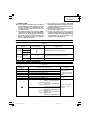
8. An extension cord should not be used unless
absolutely necessary. Use of improper extension
cord could result in a risk of fire and electric shock.
If extension cord must be used make sure:
a. That blades of extension cord are the same
number, size, and shape as those of plug on
battery charger:
b. That extension cord is properly wired and in
good electrical condition; and
c. That wire size is large enough for AC ampere
rating of battery charger as specified in Table
1.
Table 1
RECOMMENDED MINIMUM AWG SIZE FOR
EXTENSION CORDS FOR BATTERY CHARGERS
AC Input Rating Amperes* AWG Size of Cord
Equal to or but less Length of Cord, Feet (Meter)
greater than than 25 (7.5) 50 (15) 100 (30) 150 (45)
02 1818 18 16
23 1818 16 14
34 1818 16 14
1,250watts
125 volts
=
10 amperes
*
If the input rating of a battery charger is given in
watts rather than in amperes, the corresponding
ampere rating is to be determined by dividing the
wattage rating by the voltage rating–for example:
9. Do not operate battery charger with damaged cord
or plug-replace them immediately.
10. Do not operate battery charger if it has received a
sharp blow, been dropped, or otherwise damaged
in any way; take it to a qualified serviceman.
11. Do not disassemble battery charger; take it to a
qualified serviceman when service or repair is
required. Incorrect reassembly may result in a risk
of electric shock or fire.
12. To reduce risk of electric shock, unplug charger
from receptacle before attempting any
maintenance or cleaning. Removing the battery
will not reduce this risk.
IMPORTANT SAFETY INSTRUCTIONS FOR
USE OF THE BATTERY AND BATTERY
CHARGER
You must charge the battery before you can use the
cordless driver drill. Before using the model UC18YG
battery charger, be sure to read all instructions and
cautionary statements on it, the battery and in this
manual.
REMEMBER: USE ONLY HITACHI BATTERY TYPES
EB1214S, EB1414S, EB1814SL, AND EB1820L. OTHER
TYPES OF BATTERIES MAY BURST AND CAUSE
INJURY!
01Eng_DS12DVF3_US 4/9/13, 13:507

English
8
Follow these instructions to avoid the risk of injury:
WARNING:
Improper use of the battery or
battery charger can lead to serious
injury. To avoid these injuries:
1. NEVER disassemble the battery.
2. NEVER incinerate the battery, even if it is
damaged or is completely worn out. The battery
can explode in a fire.
3. NEVER short-circuit the battery.
4. NEVER insert any objects into the battery
charger’s air vents. Electric shock or damage to
the battery charger may result.
5. NEVER charge outdoors. Keep the battery away
from direct sunlight and use only where there is
low humidity and good ventilation.
6. NEVER charge when the temperature is below
50°F (10°C) or above 104°F (40°C).
7. NEVER connect two battery chargers together.
8. NEVER insert foreign objects into the hole for the
battery or the battery charger.
9. NEVER use a booster transformer when charging.
10. NEVER use an engine generator or DC power to
charge.
11. NEVER store the battery or battery charger in
places where the temperature may reach or exceed
104°F (40°C).
12. ALWAYS operate charger on standard household
electrical power (120 volts). Using the charger on
any other voltage may overheat and damage the
charger.
13. ALWAYS wait at least 15 minutes between
charges to avoid overheating the charger.
14. ALWAYS disconnect the power cord from its
receptacle when the charger is not in use.
DISPOSAL OF THE EXHAUSTED BATTERY
WARNING:
Do not dispose of the exhausted battery. The
battery must explode if it is incinerated. The
product that you have purchased contains a
rechargeable battery. The battery is recyclable. At
the end of it’s useful life, under various state and
local laws, it may be illegal to dispose of this
battery into the municipal waste stream. Check
with your local solid waste officials for details in
your area for recycling options or proper disposal.
SAVE THESE INSTRUCTIONS
AND
MAKE THEM AVAILABLE TO OTHER USERS
AND
OWNERS OF THIS TOOL!
01Eng_DS12DVF3_US 4/9/13, 13:508

English
9
FUNCTIONAL DESCRIPTION
NOTE:
The information contained in this Instruction Manual is designed to assist you in the safe operation and
maintenance of the power tool.
NEVER operate, or attempt any maintenance on the tool unless you have first read and understood all safety
instructions contained in this manual.
Some illustrations in this Instruction Manual may show details or attachments that differ from those on your
own power tool.
MODEL
DS12DVF3: with charger and case
DS14DVF3: with charger and case
DS18DVF3: with charger and case
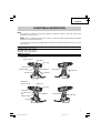
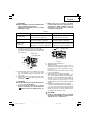
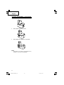
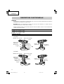
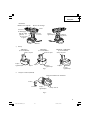
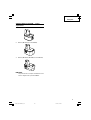
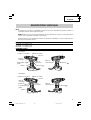
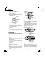
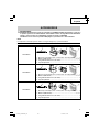
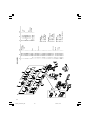
NAME OF PARTS
1. Cordless Driver Drill
<DS12DVF3>
<DS14DVF3>
Switch Trigger
Clutch Dial
Keyless Chuck
Shift Knob
Handle
Push Button
Nameplate
Housing
L
Indication
R
Indication
Battery
L
Indication
Clutch Dial
Keyless Chuck
Shift Knob
Handle
Push Button
Housing
Switch Trigger
Battery
Nameplate
R
Indication
01Eng_DS12DVF3_US 12/6/07, 11:369

English
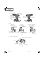
10
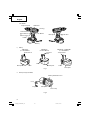
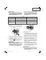
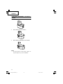
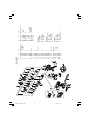
<DS18DVF3>
䡬
Battery
<EB1214S> <EB1414S> <EB1814SL or EB1820L>
(For DS12DVF3) (For DS14DVF3) (For DS18DVF3)
Nameplate
Latch
Fig. 1
2. Battery Charger (UC18YG)
Fig. 2
Latch
Nameplate
L
Indication
Clutch Dial
Keyless Chuck
Shift Knob
Handle
Push Button
Housing
Switch Trigger
Battery
Nameplate
R
Indication
Nameplate
Latch
Battery Installation Hole
Pilot Lamp
Cord
Plug
Nameplate
Terminal Hole Terminal
Hole
Terminal Hole
01Eng_DS12DVF3_US 12/6/07, 11:3610

English
11
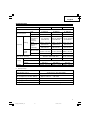
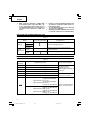
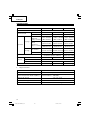
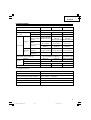
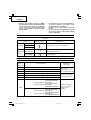
SPECIFICATIONS
1. Cordless Driver Drill
Model UC18YG
Input power source Single phase: AC 120 V 60 Hz
Charging time Approx. 30 min......
EB1214S, EB1414S, EB1814SL
(At a temperature of 68°F (20°C)) Approx. 50 min...... EB1820L
Charging voltage DC 7.2 – 18 V
Charging current DC 2.6 A
Weight 0.7 lbs. (0.3 kg)
2. Battery Charger
Model DS12DVF3 DS14DVF3 DS18DVF3
Motor DC motor
No-load speed
Low 0–350/min 0–400/min 0–400/min
High 0–1050/min 0–1200/min 0–1200/min
Wood
1 in. (25 mm)
1–3/16 in. (30 mm) 1–1/2 in. (38 mm)
(Thickness
11/16 in.
Drilling
(18 mm))
(Soft Wood) (Soft Wood) (Soft Wood)
Metal 15/32 in. (12 mm) 15/32 in. (12 mm) 1/2 in. (13 mm)
Capacity
(Thickness (Mild Steel) (Mild Steel) (Mild Steel)
1/16 in.
19/32 in. (15 mm) 19/32 in. (15 mm) 1/2 in. (13 mm)
(1.6 mm))
(Aluminum) (Aluminum) (Aluminum)
Screw
Wood screw
#12 × 2-1/2 in. #14 × 2-1/2 in. #20 × 3 in.
(5.8 mm × 63 mm) (6.2 mm × 63 mm) (8mm × 75 mm)
Driver
Small screw 1/4 in. (6 mm) 1/4 in. (6 mm) 1/4 in. (6 mm)
Drill chuck capacity
Maximum gripping
Maximum gripping
diameter 3/8 in. (10 mm)
diameter 1/2 in. (13 mm)
Model EB1214S EB1414S
EB1814SL / EB1820L
Battery Type Nickel cadmium battery
Voltage DC 12 V DC 14.4 V DC 18 V
Weight 3.3 lbs. (1.5 kg) 4.0 lbs. (1.8 kg) 4.4 lbs. (2.0 kg)
01Eng_DS12DVF3_US 12/6/07, 11:3611

English
12
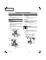
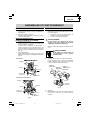
ASSEMBLY AND OPERATION
Fig. 3
Latch
Push
Handle
Pull out
Insert
Battery
Latch
Handle
Insert
Battery
Push
Pull out
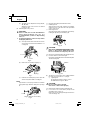
CHARGING METHOD
NOTE:
Before plugging into the receptacle, make sure the
following points.
䡬
The power source voltage is stated on the
nameplate.
䡬
The cord is not damaged.
WARNING:
Do not charge at voltage higher than indicated on
the nameplate.
If charged at voltage higher than indicated on the
nameplate, the charger will burn up.
1. Insert the plug of battery charger into the
receptacle.
WARNING:
Do not use the electrical cord if
damaged. Have it repaired immediately.
2. Insert the battery to the battery charger.
Insert the battery into the battery charger as shown
in Fig. 4. Make sure it contacts the bottom of the
battery charger.
Pilot
Lamp
Fig. 4
Battery
(EB1214S)
Battery
(EB1414S)
Battery
(EB1814SL or
EB1820L)
APPLICATIONS
䡬
Use as a drill
Drilling of soft steel, wood, plastic and aluminum
materials.
䡬
Use as a screwdriver
Tightening and loosening of machine screws,
wood screws and tapping screws.
REMOVAL AND INSTALLATION METHOD
OF BATTERY
䡬
How to install the battery.
Align the battery with the groove in tool handle
and slip it into place.
Always insert it all the way until it locks in place
with a little click, If not, it may accidentally fall out
of the tool, causing injury to you or someone
around you (Fig. 3).
䡬
How to remove the battery.
Withdraw battery from the tool handle while
pressing the latch (1 pc. or 2 pcs) of the battery
(Fig. 3).
<DS12DVF3>
<DS14DVF3 and DS18DVF3>
01Eng_DS12DVF3_US 12/6/07, 11:3712

English
13
3. Charging
䡬
When the battery is connected to the battery
charger, charging will commence and the pilot
lamp will light on.
NOTE:
If the pilot lamp dose not light, pull out the plug
from the receptacle and check if the battery is
properly mounted.
䡬
In approx. 30 – 50 min., when the battery is fully
charged, the pilot lamp will go out.
NOTE:
The battery charging time becomes longer when
a temperature is low or the voltage of the power
source is too low.
When the pilot lamp does not go off even if more
than four hour has passed after start of the
charging, stop the charging and contact your
HITACHI AUTHORIZED SERVICE CENTER.
4. Disconnect battery charger from the receptacle.
CAUTION:
Do not pull the plug out of the receptacle by
pulling on the cord.
Make sure to grasp the plug when removing from
receptacle to avoid damaging cord.
5. Remove the battery from the battery charger.
Supporting the battery charger with hand, pull out
the battery from the battery charger.
CAUTION:
●
When the battery charger has been continuously
used, the battery charger will be heated, thus
constituting the cause of the failures. Once the
charging has been completed, wait 15 minutes
rest until the next charging.
●
If the battery is recharged when it is warm due
to battery use or exposure to sunlight, the pilot
lamp may not light.
The battery will not be recharged. In such a case,
let the battery cool before charging.
Regarding electric discharge in case of new
batteries, etc.
As the internal chemical substance of new
batteries and batteries that have not been used
for an extended period is not activated, the electric
discharge might be low when using them the first
and second time. This is a temporary
phenomenon, and normal time required for
recharging will be restored by recharging the
batteries 2 – 3 times.
How to make the batteries perform longer.
(1) Recharge the batteries before they become
completely exhausted.
When you feel that the power of the tool becomes
weaker, stop using the tool and recharge its
battery. If you continue to use the tool and exhaust
the electric current, the battery may be damaged
and its life will become shorter.
(2) Avoid recharging at high temperatures.
A rechargeable battery will be hot immediately
after use. If such a battery is recharged immediately
after use, its internal chemical substance will
deteriorate, and the battery life will be shortened.
Leave the battery and recharge it after it has cooled
for a while.
BEFORE USE
Check the work area to make sure that it is clear of debris
and clutter.
Clear the area of unnecessary personnel. Ensure that
lighting and ventilation is adequate.
OPERATION
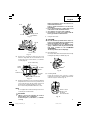
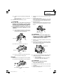
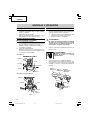
1. Using the hook (Hook with bit holder or Light
equipped hook)
WARNING:
When using the hook, pay sufficient attention so
that the main equipment does not fall. If the tool
falls, there is a risk of accident.
CAUTION:
●
Do not attach the tip tool except phillips bit to the
tool main unit when carrying the tool main unit
with the hook suspended from a waist belt.
Injury may result if you carry the equipment
suspended from the waist belt with sharp tipped
components such as drill bit attached.
The hook can be installed on the right or left side
and the angle can be adjusted in 5 steps between
0° and 80°.
(1) Operating the hook
(a) Pull out the hook toward you in the direction
of arrow (A) and turn in the direction of arrow
(B) (Fig. 5).
4
(B)
Fig. 5
3
2
1
5
Hook
(A)
01Eng_DS12DVF3_US 12/6/07, 11:3713

English
14
(b) The angle can be adjusted in 5 steps (0°, 20°,
40°, 60°, 80°).
Adjust the angle of the hook to the desired
position for use.
(2) Switching the hook position
CAUTION:
●
If the tool falls, there is a risk that malfunction
and/or physical damage can occur. It is
recommended that you also use fall-preventing
wires, etc.
●
Incomplete installation of the hook may result in
bodily injury when used.
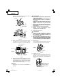
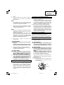
(a) Securely hold the main unit and remove the
screw using a slotted head screwdriver or a
coin (Fig. 6).
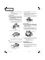
1.1 Using the bit holder (Hook with bit holder)
䡬
Installing the bit
Slide the bit from the side, and then insert firmly
until the groove on the bit locks in the protruded
section of the hook.
䡬
Removing the bit
Securely hold the main unit and pull out the bit by
holding the tip with your thumb (Fig. 9).
Fig. 6
Loosen
Screw
Fig. 7
Spring
Hook
(b) Remove the hook and spring (Fig. 7).
(c) Install the hook and spring on the other side
and securely fasten with screw (Fig. 6).
NOTE:
Pay attention to the spring orientation. Install the
spring with larger diameter away from you (Fig.
8).
Fig. 9
Fig. 10
Switch
Hook
CAUTION:
●
Only Hitachi STANDARD ACCESSORIES phillips
bit (No. 2 × 65L; Code No. 983006) may be used.
Do not use other bits since they may come loose.
1.2 Using as an auxiliary light (Light equipped hook)
(1) Press the switch to turn off the light.
If forgotten, the light will turn off automatically after
15 minutes (Fig. 10).
(2) The direction of the light can be adjusted within
the range of hook positions 1 - 5 (Fig. 5).
䡬
Lighting time
N manganese batteries: approx. 15 hrs.
N alkali batteries: approx. 30 hrs.
CAUTION:
●
Do not look directly into the light.
Such actions could result in eye injury.
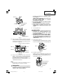
1.3 Replacing the batteries (Light equipped hook)
(1) Loosen the hook screw with a phillips-head
screwdriver (No. 1) (Fig. 11).
Remove the hook cover by pushing in the direction
of the arrow (Fig. 12).
Fig. 8
Screw
Larger diameter faces away
01Eng_DS12DVF3_US 12/6/07, 11:3714

English
15
(2) Remove the old batteries and insert the new
batteries. Align with the hook indications and
position the plus (+) and minus (–) terminals
correctly (Fig. 13).
Hook main body
Protube-
rance
Inden-
tation
N
batteries
Indentation
Protube-
rance
Hook cover
Fig. 13
Fig. 12
Arrow
Hook cover
Fig. 11
Hook
Phillips-head
screwdriver
Screw
(3) Align the indentation in the hook main body with
the protuberance of the hook cover, press the hook
cover in the direction opposite to that of the arrow
shown in Fig. 12 and then tighten the screw.
Use commercially available N batteries (1.5 V).
NOTE:
Do not tighten the screw excessively. Such action
could strip the screw threads.
CAUTION:
●
Failure to observe the following can result in
battery leakage, rust or malfunction.
Position the plus (+) and minus (–) terminals
correctly.
Replace both batteries at the same time. Do not
mix old and new batteries.
Remove exhausted batteries from the hook
immediately.
●
Do not discard batteries together with normal
trash and do not throw batteries into fire.
●
Store batteries out of the reach of children.
●
Use batteries correctly in accordance with the
battery specifications and indications.
2. Using the bit holder.
CAUTION:
●
Stow the bit in the specified location on the tool.
If the tool is used with the bit stowed improperly,
the bit may fall and cause bodily injury.
●
Do not stow bits that are of a different length,
gauge or dimension than the plus driver bit (65
mm long) included in the STANDARD
ACCESSORIES.
The bit may fall and cause bodily injury.
(1) Removing the bit
Securely hold the main unit and pull out the bit by
holding the tip with your thumb (Fig. 14).
Fig. 14
Bit
Fig. 15
Insert so that
bit does not
protrude
from main unit
(2) Installing the Bit
Install the bit with steps opposite of when
removing. Insert the bit so that the right and left
sides are equal, as shown in Fig. 15.
01Eng_DS12DVF3_US 12/6/07, 11:3715

English
16
3. Mounting and dismounting of the bit.
(1) Mounting the bit.
Insert a screwdriver bit etc. into the keyless drill
chuck.
Firmly grasp the ring and tighten the sleeve by
turning it toward the right (in the clockwise
direction as viewed from the front) (See Fig. 16).
Fig. 16
Tighten
Loosen
SleeveRing
NOTE:
If the sleeve becomes loose during operation,
tighten it further.
The tightening force becomes stronger when the
sleeve is tightened.
(2) Dismounting the bit
Firmly grasp the ring and loosen the sleeve by
turning it toward the left (in the counterclockwise
direction as viewed from the front) (See Fig. 16).
CAUTION:
When mounting a bit into the keyless chuck,
tighten firmly. If the sleeve is not tight, the bit may
slip or fall out, causing injury.
NOTE:
Loosening stuck or hard to move sleeves.
Grasp the bit installed in the keyless chuck, in a
vise or similar tool.
Set the clutch dial position to “1-11” and turn on
the switch. The motor then starts.
Finally, rotate the sleeve to the left, and it will
loosen.
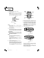
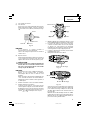
4. Confirm that the battery is mounted correctly.
5. Check the rotational direction.
The bit rotates clockwise (viewed from the rear
side) by pushing the R-side of the selector button.
The L-side of the selector button is pushed to turn
the bit counterclockwise (See Fig. 17).
(The
L
and
R
marks are provided on the body.)
LR
Fig. 17
Selector
button
R
marks
Trigger
switch
L
marks
䡬
When the trigger switch is depressed, the tool
rotates. When the trigger is released, the tool stops.
䡬
The rotational speed of the drill can be controlled
by varying the amount that the trigger switch is
pulled. Speed is low when the trigger switch is
pulled slightly and increases as the trigger switch
is pulled more.
䡬
When releasing the trigger of the switch, the brake
will be applied for immediate stopping.
6. Change rotation speed.
Fig. 18
Shift knob
High speed
Fig. 19
Shift knob
Low speed
Operate the shift knob to change the rotational
speed. Move the shift knob in the direction of the
arrow (see Figs. 18 and 19).
When the shift knob is set to “LOW”, the drill
rotates at a low speed. When set to “HIGH”, the
drill rotates at a high speed.
01Eng_DS12DVF3_US 12/6/07, 11:3716

English
17
CAUTION:
●
When changing the rotational speed with the shift
knob, confirm that the switch is off.
Changing the speed while the motor is rotating
will damage the gears.
●
When a large force is required for operation
(operations indicated in the following chart) set
the shift knob to “LOW”. If “HIGH” is set and the
unit is used, it may cause the motor to burn out
or malfunction prematurely.
Table 2
Model DS12DVF3 / DS14DVF3 DS18DVF3
Metal Drilling
Wood Drilling
Wood Screw
Tightening
When the diameter of the hole
exceeds 1/4 in. (6.5 mm).
When the diameter of the hole
exceeds 15/32 in. (12 mm).
When the size of the wood
screw exceeds 5/32 in. (3.8 mm)
diameter × 1-31/32 in. (50 mm).
When the diameter of the hole
exceeds 5/16 in. (8 mm).
When the diameter of the hole
exceeds 15/16 in. (24 mm).
When the size of the wood
screw exceeds 3/16 in. (4.8 mm)
diameter × 1-9/16 in. (40 mm).
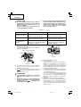
7. Confirm the clutch dial position (see Fig. 20).
The tightening torque of this unit can be adjusted
according to the clutch dial position, at which the
clutch dial is set.
8. Tightening torque adjustment.
(1) Tightening torque
Tightening torque should correspond in its
intensity to the screw diameter. When too strong
power is used, the screw head may be broken or
be injured.
Be sure to adjust the clutch dial position according
to the screw diameter.
(2) Tightening torque indication (See Fig. 20)
The tightening torque differs depending on the
type of screw and the material being tightened.
The unit indicates the tightening torque with the
numbers “1, 3, 5 ... 22” on the clutch dial, and a
dot. The tightening torque at position “1” is the
weakest and the torque is strongest at the highest
number.
(3) Adjusting the tightening torque (See Fig. 20)
Rotate the clutch dial and line up the numbers “1,
3, 5, ... 22” on the clutch dial, or the dot, with the
triangle mark on the outer body. Adjust the clutch
dial in the weak or the strong torque direction
according to the torque you need.
CAUTION:
●
The motor rotation may be locked to cease while
the unit is used as drill. While operating the driver
drill, take care not to lock the motor.
Clutch dial
Triangle mark
Fig. 20
Weak
mark
Strong
Line
mark
Fig. 21
Triangle mark
(1) When using this unit as a screwdriver, line up the
one of the numbers “1, 3, 5 ... 22” on the clutch
dial, or the black dot, with the triangle mark on the
outer body.
(2) When using this unit as a drill, line up the clutch
dial drill mark “ ” with the triangle mark on the
outer body.
CAUTION:
●
The clutch dial cannot be set between the numbers
“1, 3, 5 ... 22” or the black dot.
●
Do not use with the clutch dial set at the line
between the number “22” and the drill mark
“ ”. Doing so may cause damage (See Fig. 21).
01Eng_DS12DVF3_US 12/6/07, 11:3717

English
18
●
When setting the shift knob to “HIGH” (high
speed) and the position of the clutch dial is “17”
to “22”, it may happen that the clutch does not
engaged and that the motor is locked. In such a
case, please set the shift knob to “LOW” (low
speed).
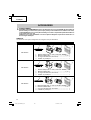
THE SCOPE AND SUGGESTIONS FOR USES
Table 3
●
If the motor is locked, immediately turn the power
off. If the motor is locked for a while, the motor or
battery may be burnt.
●
Too long hammering may cause the screw broken
due to excessive tightening.
●
A buzzing noise is produced when the motor is about
to rotate; This is only a noise, not a machine failure.
Work Clutch dial position Suggestions
Wood
Drilling Steel Use for drilling purpose.
Aluminum
Machine
1 – 22
Use the bit and socket matching the
Screw
screw screw diameter.
tightening
Wood
1 –
Use after drilling a pilot hole.
screw
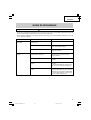
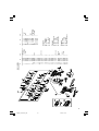
HOW TO SELECT TIGHTENING TORQUE
Table 4
Clutch dial
Tightening torque Operation example
position
Approximately 9 in.-lbs. (10 kg-cm)
Approximately 15 in.-lbs. (17 kg-cm)
Approximately 23 in.-lbs. (26 kg-cm)
Approximately 35 in.-lbs. (40 kg-cm)
Approximately 43 in.-lbs. (49 kg-cm)
Approximately 52 in.-lbs. (60 kg-cm)
High speed: approximately 61 in.-lbs.
(70 kg-cm) (DS12DVF3)
approximately 71 in.-lbs.
(82 kg-cm) (DS14DVF3)
approximately 97 in.-lbs.
(112 kg-cm) (DS18DVF3)
Low speed: approximately 230 in.-lbs.
(265 kg-cm) (DS12DVF3)
approximately 300 in.-lbs.
(347 kg-cm) (DS14DVF3)
approximately 400 in.-lbs.
(459 kg-cm) (DS18DVF3)
Machine screw
tightening Screw
tightening for soft wood
material
Screw tightening for
hard wood material
Thick screw tightening
When used as a drill.
1
3
7
13
17
22
01Eng_DS12DVF3_US 12/6/07, 11:3718

English
19
MAINTENANCE AND INSPECTION
CAUTION:
Pull out battery before doing any inspection or maintenance.
1. Checking the condition of the bit
The bits should be checked regularly. If worn or
broken bits can slip or decrease the efficiency of
the motor and burn it out.
Replace worn bits with new ones.
CAUTION:
If you use a driver bit of which point is worn or
broken, it will be dangerous since it slips. So
replace it with a new one.
2. Check the Screws
Loose screws are dangerous. Regularly inspect
them and make sure they are tight.
CAUTION:
Using this power tool with loosened, screws is
extremely dangerous.
3. Check for Dust
Dust may be removed with a soft cloth or a cloth
dampened with soapy water.
Do not use bleach, chlorine, gasoline or thinner,
for they may damage the plastics.
4. Disposal of the exhausted battery
WARNING:
Do not dispose of the exhausted battery. The
battery must explode if it is incinerated. The
product that you have purchased contains a
rechargeable battery. The battery is recyclable. At
the end of it’s useful life, under various state and
local laws, it may be illegal to dispose of this
battery into the municipal waste stream. Check
with your local solid waste officials for details in
your area for recycling options or proper disposal.
5. Storage
Storing in a place below 104°F (40°C) and out of
the reach of children.
6. Service and repairs
All quality power tools will eventually require
servicing or replacement of parts because of wear
from normal use. To assure that only authorized
replacement parts will be used, all service and
repairs must be performed by a HITACHI
AUTHORIZED SERVICE CENTER, ONLY.
7. Service parts list
CAUTION:
Repair, modification and inspection of Hitachi
Power Tools must be carried out by an Hitachi
Authorized Service Center.
This Parts List will be helpful if presented with the
tool to the Hitachi Authorized
Service Center when requesting repair or other
maintenance. In the operation and maintenance
of power tools, the safety regulations and
standards prescribed in each country must be
observed.
MODIFICATIONS:
Hitachi Power Tools are constantly being improved
and modified to incorporate the latest
technological advancements.
Accordingly, some parts (i.e. code numbers and/
or design) may be changed without prior notice.
NOTE:
The selected content shown in Table 4 indicates
the differences according to screw type, screw size
and material used.
CAUTION:
●
While operating the Cordless driver drill, take care
not to lock the motor.
If the motor is locked, immediately turn the power
off.
If the motor is locked for a while, the motor or
battery will be burnt.
●
Do not tighten too strongly as the screw heads
will be damaged.
01Eng_DS12DVF3_US 12/6/07, 11:3719

English
20
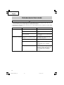
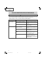
TROUBLESHOOTING GUIDE
•
To avoid injury from an accidental start, turn the switch OFF and remove the plug from the power source or
remove the battery from the main body before making any adjustments.
•
All electrical or mechanical repairs should be done only by qualified service technicians. Contact Hitachi
Authorized Service Center.
WARNING
Problem Possible Cause Possible Solution
Tool will not start.
Battery will not charged.
Battery not installed properly.
Battery not charged.
Battery overheated.
Battery pack not installed into Charger
properly.
Charger not plugged in.
Battery temperature too hot
Battery temperature too cold
Check the battery installation.
Charge battery using appropriate
charger.
Remove battery from tool and let battery
cool for while.
Insert battery into charger until charge
status lamp (red) appears.
Plug charger into a working receptacle.
Remove battery from charger, cool
battery.
For more detail, refer to “Charging
Method”.
Remove battery from charger, move
battery and charger to a surrounding air
temperature of above 50°F (10°C).
For more detail, refer to “Changing
Method”.
01Eng_DS12DVF3_US 12/6/07, 11:3720
La page charge ...
La page charge ...
La page charge ...
La page charge ...
La page charge ...
La page charge ...
La page charge ...
La page charge ...
La page charge ...
La page charge ...
La page charge ...
La page charge ...
La page charge ...
La page charge ...
La page charge ...
La page charge ...
La page charge ...
La page charge ...
La page charge ...
La page charge ...
La page charge ...
La page charge ...
La page charge ...
La page charge ...
La page charge ...
La page charge ...
La page charge ...
La page charge ...
La page charge ...
La page charge ...
La page charge ...
La page charge ...
La page charge ...
La page charge ...
La page charge ...
La page charge ...
La page charge ...
La page charge ...
La page charge ...
La page charge ...
La page charge ...
La page charge ...
La page charge ...
La page charge ...
-
 1
1
-
 2
2
-
 3
3
-
 4
4
-
 5
5
-
 6
6
-
 7
7
-
 8
8
-
 9
9
-
 10
10
-
 11
11
-
 12
12
-
 13
13
-
 14
14
-
 15
15
-
 16
16
-
 17
17
-
 18
18
-
 19
19
-
 20
20
-
 21
21
-
 22
22
-
 23
23
-
 24
24
-
 25
25
-
 26
26
-
 27
27
-
 28
28
-
 29
29
-
 30
30
-
 31
31
-
 32
32
-
 33
33
-
 34
34
-
 35
35
-
 36
36
-
 37
37
-
 38
38
-
 39
39
-
 40
40
-
 41
41
-
 42
42
-
 43
43
-
 44
44
-
 45
45
-
 46
46
-
 47
47
-
 48
48
-
 49
49
-
 50
50
-
 51
51
-
 52
52
-
 53
53
-
 54
54
-
 55
55
-
 56
56
-
 57
57
-
 58
58
-
 59
59
-
 60
60
-
 61
61
-
 62
62
-
 63
63
-
 64
64


Hitachi DS14DVF3 Safety Instructions And Instruction Manual
- Catégorie
- Outils électroportatifs
- Taper
- Safety Instructions And Instruction Manual
dans d''autres langues
- English: Hitachi DS14DVF3
- español: Hitachi DS14DVF3
Documents connexes
-
Hitachi WH14DM Manuel utilisateur
-
Hitachi WH 14DAF2 Safety And Instruction Manual
-
-
-
Hitachi DS 12DVF3 Manuel utilisateur
-
-
-
-
-
Hitachi DS14DVF3 Le manuel du propriétaire