
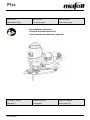
P1cc
170761.0922/b
IMPORTANT
Read Before Using
IMPORTANT
Lire avant usage
IMPORTANTE
Leer antes de usar
Operating/Safety Instructions
Consignes d’utilisation/de sécurité
Instrucciones de funcionamiento y seguridad
For English Version
See page 2
Version française
Voir page 23
Versión en español
Ver la página 44

P1cc
2
09/2022
English
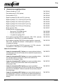
Table of contents
1 Signs and symbols ........................................................................................................... 3
1.1 Identification of the device ................................................................................................ 5
2 Product specifications ...................................................................................................... 5
2.1 Technical data .................................................................................................................. 5
2.2 Scope of delivery .............................................................................................................. 6
2.3 Adjustment elements ........................................................................................................ 6
3 General safety .................................................................................................................. 7
3.1 Intended use ..................................................................................................................... 7
3.2 Foreseeable misuse ......................................................................................................... 7
3.3 Safety instructions ............................................................................................................ 8
3.4 Specific safety rules ......................................................................................................... 9
3.5 Safety devices ................................................................................................................ 10
3.6 Residual risks ................................................................................................................. 11
4 Setup / adjustment ......................................................................................................... 11
4.1 Mains connection ........................................................................................................... 11
4.2 Routing of the connecting cable ..................................................................................... 11
4.3 Chip extraction ............................................................................................................... 12
4.4 Changing the saw blade ................................................................................................. 12
4.5 Base plate ...................................................................................................................... 13
4.6 Hose connector .............................................................................................................. 14
4.7 Using the precision jigsaw on the guide rail ................................................................... 15
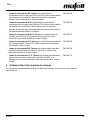
5 Operation ........................................................................................................................ 16
5.1 Startup ............................................................................................................................ 16
5.2 Switching on / off ............................................................................................................ 16
5.3 Pendulum stroke adjustment .......................................................................................... 17
5.4 Tear-free sawing ............................................................................................................ 17
5.5 Positioning the base plate .............................................................................................. 17
5.6 Backward sawing ........................................................................................................... 18
5.7 Working with the parallel guide fence ............................................................................. 18
6 Service and maintenance ............................................................................................... 19
6.1 Storage ........................................................................................................................... 19
7 Troubleshooting .............................................................................................................. 19
8 Optional accessories ...................................................................................................... 21
9 Exploded view and spare parts list ................................................................................. 22

P1cc
09/2022
3
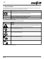
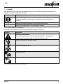
1 Signs and symbols
These operating instructions contain the following general information signs to guide you, the reader, through
the operating instructions and to provide you with important information.
Sign
Meaning
Important information
This sign highlights user tips and other useful information.
➢
Identifies an intermediate result in a sequence of actions.
✓
Identifies the final result of a sequence of actions.
Tab. 1: General signs and their meanings
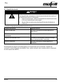
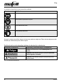
Warning icons warn of dangerous points, risks and obstacles.
Icon
Meaning
Warning
This icon can be found at all locations where you can find information regarding your
safety. Non-observance can result in extremely serious injuries.
Warns of danger of electric shock.
Warns of danger caused by dust.
Warns of the danger of cutting.
Warns of the danger of cutting off or severing limbs.
Tab. 2: Warning icons and their meanings

P1cc
4
09/2022
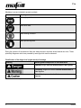
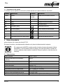
Mandatory icons are intended to prevent accidents.
Icon
Meaning
Wear eye protection.
Wear dust mask.
Wear hearing protection.
Wear protective gloves.
Tab. 3: Mandatory icons and their meanings
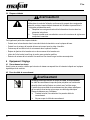
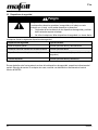
During the operation of the power tool there are always actions to be taken where hazards can occur. These
potentially dangerous actions are preceded by warnings which must be observed.
Classification of the danger level (signal words) of warnings
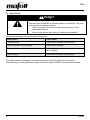
Warning
Meaning and consequences of non-observance
Imminent danger that will cause serious or fatal injuries.
Potentially dangerous situation that can cause serious or
fatal injuries.
Potentially dangerous situation that can cause minor
injuries.
Tab. 4: Structure of warnings

P1cc
09/2022
5
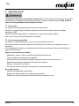
1.1 Identification of the device
The icons listed and explained below can be found on the rating plate or on the product.
Symbol
Explanation
Symbol
Explanation
V
Volt
1, 2, 3, ...
I, II, III, ...
Rotational speed setting
A
Ampere
rpm
Revolutions per minute
Hz
Hertz
ø
Saw blade diameter
W
Watt
~
Alternating current
kg
Kilogram (weight)
Protection class II
min
Minutes (time)
Read operating instructions
s
Seconds (time)
Protective goggles
n0
Rated speed at no load
Hearing protection
n
Rated speed at normal load
Dust mask
2 Product specifications
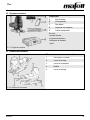
for machines with item number 917123
The article number and machine number are listed on the type plate of the machine.
By entering the article number and machine number on the MAFELL homepage, you can
call up the spare parts lists, exploded drawings, and other product information belonging
to your machine (see also Chapter 9 Exploded view and spare parts list).
2.1 Technical data
Universal motor
120 V~, 60 Hz
Power consumption (continuous operation)
900 W
Current at normal load
7 A
Stroke rate in no-load operation
800 to 3000 rpm
Stroke/working distance
26 mm [1 in]
Cutting depth
65/115 mm [2.56/4.53 in]
Cutting speed at normal load
0.4 - 1.3 m/s [1.31 - 4.26 ft/s]
Hose connector diameter
29 mm [1.14 in]
Weight without power cord
2.5 kg [5.51 lbs]
Dimensions (width x length x height)
90 x 230 x 180 mm [3.54 x 9.06 x 7.09 in]

P1cc
6
09/2022
2.2 Scope of delivery
Fig. 1: Scope of delivery
Components
A
Jigsaw
B
Parallel guide fence
C
Chip breaker guard
D
Jigsaw blades
E
Transport box
Additionally included:
1 base plate
1 hose connector
1 chip deflector
1 glider
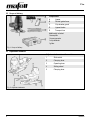
2.3 Adjustment elements
Fig. 2: Adjustment elements
Adjustment elements on the machine
1
Slide switch
2
Clamping lever
3
Operating lever
4
Setting wheel
5
Clamping lever

P1cc
09/2022
7
3 General safety
Please read all safety instructions and directions. Failure to comply with the safety instructions and
directions can cause electric shock, fire and/or serious injuries. Please retain all safety instructions and
directions for future reference.
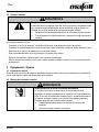
3.1 Intended use
The machine is only suitable for cutting solid wood.
Panel material such as chip board, core board and medium density fiber board can also be processed.
Processing plastics, mineral building materials and metals is also possible.
Use only saw blades that are approved by the manufacturer.
3.2 Foreseeable misuse
The machine is not intended for any other use than the intended use listed above.
The manufacturer is not liable for any damage resulting from such other use.
To use the machine as intended, comply with the operating, maintenance and repair conditions specified by
MAFELL.
Foreseeable misuse also includes:
- Tampering with, removing and/or bypassing safety devices of any kind.
- Operating the machine without safety devices.
- Non-observance of safety and warning instructions in the operating instructions.
- Removing the safety and warning labels from the machine.
- Operating the machine by unauthorized persons.
- Failure to follow prescribed maintenance and care instructions.
Never use:
- Cracked and/or deformed saw blades.
- Blunt saw blades as they impose an excessive load on the motor.
- Saw blades that are not suitable for the stroke rate in no-load operation.

P1cc
8
09/2022
3.3 Safety instructions
READ ALL INSTRUCTIONS!
Non-observance of the instructions listed below can cause electric shock, fire and/or serious injuries.
Work area
- Children and adolescents are not allowed to operate this machine.
- When using the machine outdoors, the use of an earth leakage circuit breaker is recommended.
- Replace damaged cables or plugs immediately. To avoid safety hazards, only MAFELL or an authorized
MAFELL service workshop is allowed to replace parts.
- Prevent sharp kinks of the cable. Do not wrap the cable around the machine, especially when transporting
and storing the machine.
- Do not use this machine when you are tired, or under the influence of drugs, alcohol or medicaments. Be
aware of what you are doing. Stay alert and use common sense.
- Keep children and bystanders at a distance while you are operating the machine. Distractions can cause
you to lose control of the machine.
- Use eye protection, dust mask and hearing protection. Appropriate safety equipment, used
under proper conditions, will reduce the risk of injuries.
Instructions for service and maintenance:
- Cleaning the machine regularly, especially the adjustment elements and the guiding devices, is an important
safety factor.
- Ensure that only genuine MAFELL spare parts and accessories are used. Failure to do so will make
warranty claims and the liability of the manufacturer null and void.
- Prepare a periodic maintenance schedule for your machine. When you clean the machine, be careful
not to disassemble any part of the machine. Reassembling the machine bears the risk that internal
wires are routed incorrectly or pinched, or that return springs of the safety device are mounted
incorrectly. Certain cleaning agents, such as gasoline, carbon tetrachloride, ammonia, etc. can damage
plastic parts.
- Some of the dust produced by sawing, sanding, drilling and other building work contains chemicals
known to cause cancer, birth defects or other reproductive harm. Some examples of these
chemicals are:
- Lead from lead-based paints,
- Crystalline silica from bricks and cement and other masonry products,
- Arsenic and chromium from chemically treated wood.
Your risk from this hazard varies with the frequency at which you perform this type of work. To reduce your
exposure to these chemicals: Work in a well-ventilated area. Work only with approved safety equipment,
such as dust masks that are specially designed to filter out particles of microscopic size.

P1cc
09/2022
9
3.4 Specific safety rules
Sawing method
- DANGER: Keep hands away from cutting area and the blade. Keep your second hand on auxiliary
handle, or motor housing. If both hands are holding the saw, they cannot be cut by the blade.
- Do not reach underneath the workpiece.
- Never hold the workpiece in your hands or across your leg while cutting. Secure the workpiece to a
stable platform. It is important to support the work properly to minimize body exposure, blade binding, or
loss of control.
- Hold the power tool by insulated gripping surfaces, when performing an operation where the cutting
tool may contact hidden wiring or its own cord. Contact with a "live" wire will also make exposed metal
parts of the power tool "live" and could give the operator an electric shock.
- Use clamps or another practical way to secure and support the workpiece to a stable platform.
Holding the workpiece by your hand or against the body leaves it unstable and may lead to loss of control.
Kickback - causes and related safety instructions
Kickback is the result of saw misuse and/or incorrect operating procedures or conditions and can be avoided
by taking proper precautions as given below.
- When blade is binding, or when interrupting a cut for any reason, release the trigger and hold the
saw motionless in the material until the blade comes to a complete stop. Never attempt to remove
the saw from the work or pull the saw backward while the blade is in motion or kickback may occur.
Investigate and take corrective actions to eliminate the cause of blade binding.
- When restarting a saw in the workpiece, centre the saw blade in the kerf so that the saw teeth are
not engaged into the material. If a saw blade binds, it may walk up or kickback from the workpiece as the
saw is restarted.
- Support large panels to minimise the risk of blade pinching and kickback. Large panels tend to sag
under their own weight. Supports must be placed under the panel on both sides, near the line of cut and
near the edge of the panel.
- Do not use dull or damaged blades. Unsharpened or improperly set blades produce narrow kerf causing
excessive friction, blade binding and kickback.
- Prior to starting sawing, tighten the cutting depth and cutting angle settings. If the settings change
during the sawing process there is a risk of a jamming saw blade and kickback.
- Use extra caution when sawing into existing walls or other blind areas. The protruding blade may cut
objects that can cause kickback.
RETAIN THESE INSTRUCTIONS!

P1cc
10
09/2022
3.5 Safety devices
Danger
Risk of injury from missing safety devices
These devices are necessary for the safe operation of the machine. They must
not be removed or rendered ineffective.
➢ Check the proper functioning of the safety devices before you start
operating the machine.
➢ Never use the machine with missing or ineffective safety devices.
The machine is equipped with the following safety devices:
Safety device
Type of check
Large base plate
Visual check for damage and deformation
Contact protection of the saw blade
Visual check for damage
Switching device and brake
Functional check (braking time must not be longer
than 7 seconds)
Hose connector
Visual check for damage and obstruction
If the safety devices are damaged or not functioning properly, follow the instructions in the chapter
Troubleshooting. For other malfunctions, please contact your dealer or MAFELL Customer Service directly.

P1cc
09/2022
11
3.6 Residual risks
Warning
Risk of injury when working with the machine
Even when the machine is used as intended and in compliance with the safety
regulations, there are still residual risks caused by the intended use, which can
have consequences for your health.
➢ Observe the safety instructions and information in these instructions.
➢ Always be extremely careful and cautious when you work with the machine.
The existing residual risks include:
- Contact with the saw blade in the area of the start-up opening below the base plate.
- Contact with the part of the saw blade that protrudes below the workpiece during the cutting process.
- Kickback of the machine when jammed in the workpiece.
- Breakage and ejection of the saw blade or parts of the saw blade.
- Impaired hearing when working without hearing protection for long periods of time.
- Emission of harmful wood dusts during longer operation without extraction.
4 Setup / adjustment
4.1 Mains connection
Prior to starting up the machine, check to ensure that the mains voltage corresponds to the operating voltage
specified on the rating plate of the machine.
4.2 Routing of the connecting cable
Warning
Electric shock when cutting into the connecting cable
The connecting cable can impair safety functions and work functions and
get into contact with the cutting tool. Cutting into the connecting cable of
the machine puts the metal parts of the machine under tension and
causes an electric shock. There is a risk of injury for the user.
➢ When working, pay attention to the way the connecting cable is
routed.
➢ Never cut into the connecting cable of your machine.

P1cc
12
09/2022
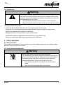
4.3 Chip extraction
Caution
Health hazards from wood dust
The dusts produced during work can be inhaled and can cause health damage.
➢ Harmful dust must be extracted with a HEPA 13 dust extractor.
➢ Wear a dust mask during work.
For all work that produces a significant amount of dust, connect the machine to a suitable external extraction
device. The air velocity must be at least 20 m/s [65 ft/sec].
The outside diameter of the hose connector is 29 mm [1.14 in].
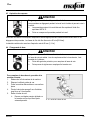
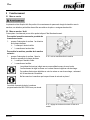
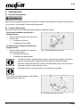
4.4 Changing the saw blade
Caution
Risk of injury from the sharp saw blade
The saw blade is sharp. You can hurt yourself when you change the saw blade.
➢ Wear protective gloves when you change the saw blade.
➢ Be careful when you change the saw blade.
Use the following procedure to change the saw
blade:
1. Pull out the power plug of the machine.
2. Put down the cable where you can see it.
3. Put the disconnected machine on a flat
surface.
4. Swivel the clamping lever (2) outward until it
locks into place.
5. Remove the saw blade.
➢ The saw blade is ejected automatically
when you press lightly on its side.
Fig. 3: Removing the saw blade

P1cc
09/2022
13
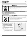
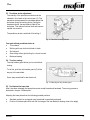
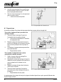
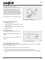
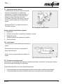
6. When inserting the new jigsaw blade, ensure
that the new blade locks into place by itself.
7. Push the clamping lever (2) back to its original
position to close it.
✓ The saw blade is changed.
Fig. 4: Replacing the saw blade
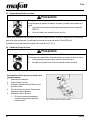
4.5 Base plate
The machine is equipped with a base plate that permits precise rectangular cuts to be made.
Use the following procedure to remove the base
plate:
1. Rotate the clamping lever (5) from the
horizontal to the vertical position.
➢ This releases the connection between
the machine and the base plate.
2. Move the base plate until the pointer position
on the machine meets the notch in the base
plate.
3. You can now separate machine and base
plate from each other.
✓ Base plate removed.
Fig. 5: Removing the base plate
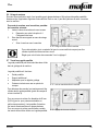
Use the following procedure to put the base
plate back on:
1. Ensure that the clamping lever (5) is in the
vertical position
2. Connect machine and base plate such that the
pointer on the machine and the pointer on the
plates are one above the other.
3. Move the base plate in the desired direction
with respect to the machine
4. Rotate the clamping lever (5) to the horizontal
position to fasten the base plate at the
machine.
✓ Base plate mounted.
Fig. 6: Mounting the base plate
Replace the base plate with the swivel plate, which is available as a special accessory, if you want to make
precise angle cuts.

P1cc
14
09/2022
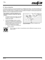
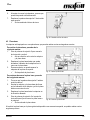
4.6 Hose connector
The machine is delivered with a hose connector and a chip deflector. Use the hose connector to connect a
suitable external extraction device. Use the chip deflector if you cannot suck off the developing dust. The
deflector directs the dust away from the user. Both parts can optionally be mounted on the base plate of the
machine.
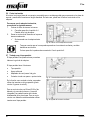
Use the following procedure to change the hose
connector or the chip deflector:
1. Press the two spring arms (6) together and
pull out the hose connector or chip deflector
from the rear.
2. When assembling, push the hose connector or
chip deflector into the opening at the rear end
of the base plate until the spring arms (6) lock
into place on their own.
✓ Hose connector or chip deflector
changed.
Fig. 7: Changing hose connector or chip deflector
For sawing under the table, the chip deflector can be rotated through 180° when it is
installed.

P1cc
09/2022
15
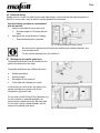
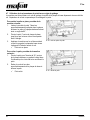
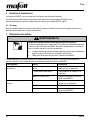
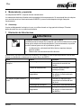
4.7 Using the precision jigsaw on the guide rail
The machine can be used on the guide rail. One half of the base plate protrudes beyond the rail in this case.
The rail thickness is compensated for by mounting a glider.
Use the following procedure to install the glider:
1. Insert the hook of the glider (7) into the
recesses provided on the base plate. Glider
and base plate form an angle of approximately
30°.
2. Press the glider (7) against the base plate until
the pin engages in the borehole.
3. Position the machine on the rail such that the
groove of the base plate engages over the
spring of the rail.
✓ Glider installed.
Fig. 8: Installing the glider
Use the following procedure to remove the
glider:
1. Reach with your finger into the recess
provided and lift the glider. Swivel the glider to
a position approx. 30° away from the base
plate.
2. Remove the hook from the recesses of the
base plate and remove the glider.
✓ Glider removed.
Fig. 9: Removing the glider

P1cc
16
09/2022
5 Operation
5.1 Startup
These operating instructions must be brought to the attention of all persons entrusted with the operation of the
machine, with particular emphasis on the chapter "Safety instructions".
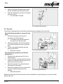
5.2 Switching on / off
There are markings on the slide switch that indicate the switching state.
Use the following procedure to switch on the
machine:
1. Push the slide switch (1) in the direction of the
base plate.
➢ Marking I is visible.
✓ The machine is switched on.
Use the following procedure to switch off the
machine:
1. Push the slide switch (1) away from the base
plate.
➢ Marking 0 is visible.
✓ The machine is switched off.
Fig. 10: Switching the machine ON/OFF
When the machine is switched on, the integrated electronics ensure jerk-free
acceleration and, under load, readjust the speed to the fixed set value.
In addition, these electronics regulate the motor back in case of overload, i.e. the saw
blade is stopped.
Switch on the machine only when the saw blade is inserted.
At the setting wheel (4), you can adjust the
rotational speed continuously between 800 and
3000 rpm.
Fig. 11: Selecting the rotational speed at the setting wheel

P1cc
09/2022
17
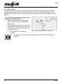
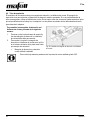
5.3 Pendulum stroke adjustment
The intensity of the pendulum movement can be
selected in four levels at the control lever (3). The
pendulum stroke presses the saw blade against the
workpiece during the working stroke. During the
downward stroke, the saw blade is lifted off the
workpiece. This reduces frictional heat and ensures
optimal chip removal.
The pendulum stroke is switched off at setting 0.
Fig. 12: Pendulum stroke adjustment
You work without pendulum stroke at:
• Thin material
• Working with rasp, butt tooth blade or blade
• Soft material
• Saw-cutting without pilot drilling for cut-outs in wood
• Backward sawing
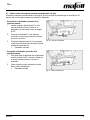
5.4 Tear-free sawing
The chip breaker guard allows you to work without
tearing.
To do this, push the chip breaker guard (C) all the
way up to the saw blade.
Use a sharp saw blade for tear-free work!
Fig. 13: Mounting the chip breaker guard
5.5 Positioning the base plate
After it has been released, the base plate can be moved forward and backward. The moving process is
described in chapter 4.5 Base plate.
Adjusting the base plate allows the following possible positions:
• Standard position for rectangular cuts (saw blade is completely enclosed).
• Position of the base plate flush with the front edge of the saw blade (for sawing close to the edge).

P1cc
18
09/2022
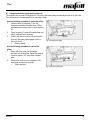
5.6 Backward sawing
Sawing close to a corner can mean that the base plate support is very small and that angular approach is
difficult. In such a case, it may be useful to saw backwards with the machine.
Use the following procedure to saw backward
with the machine:
1. Insert the saw blade the wrong way round.
➢ See also chapter 4.4 Changing the saw
blade.
2. Saw against the normal direction of sawing.
✓ Sawn backwards with the machine
Fig. 14: Sawing backwards with the machine
Be aware that the pendulum stroke cannot be used during this sawing operation, and
must be switched off.
For this, set the operating lever (3) to position 0.
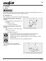
5.7 Working with the parallel guide fence
The parallel guide fence B can be inserted into the
guide of the machine on both sides.
The parallel guide fence has 4 different functions:
• Parallel guide fence
• Ancillary support
• Rail adapter for the guide rail
• Circle cutter with compass pin or point
Fig. 15: Switching the machine ON/OFF
In the function as a circle cutter, the inserts in the
parallel guide fence (compass point (8) and
compass pin (9)) can be used.
For a circular cut with 68 mm [2.68 in] diameter (e.g.
for cavity sockets or recessed spotlights), the
inserts can be inserted directly into the base plate.
For a circular cut with variable diameter, use the
inserts on the parallel guide fence.
Fig. 16: Pendulum stroke adjustment

P1cc
09/2022
19
6 Service and maintenance
MAFELL machines are of a low-maintenance design.
The installed ball bearings are lubricated for life. After a longer period of operation, MAFELL recommends that
the machine be handed over to an authorized MAFELL service workshop for inspection.
6.1 Storage
Clean the machine thoroughly if you will not use it for quite some time. Spray bare metal parts with a rust
inhibitor.
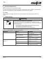
7 Troubleshooting
Warning
Risk of injury from a sudden start of the machine.
There is a risk that the machine starts suddenly due to carelessness when
working with the machine or during troubleshooting. The rotating saw blade can
cause serious injuries.
➢ Determining the causes of existing malfunctions and their elimination
always require increased attention and caution!
➢ Pull out the mains plug before you start troubleshooting!
Some of the most common malfunctions and their causes are listed below. For other malfunctions, please
contact your dealer or MAFELL Customer Service directly.
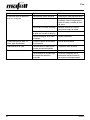
Malfunction
Cause
Elimination
Machine can not be switched on
Mains voltage missing or too low
Have the power supply checked
by an electrician
Mains fuse defective
Have the fuse replaced by an
electrician
Carbon brushes worn out
Take the machine to the MAFELL
customer service workshop
Machine stops during the cutting
process
Mains failure
Have the mains back-up fuses
checked by an electrician
Machine overload
Reduce feed rate
Carbon brushes worn out
Take the machine to the MAFELL
customer service workshop

P1cc
20
09/2022
Malfunction
Cause
Elimination
Saw blade jams when pushing
the machine forward
Feed rate too high
Reduce feed rate
Blunt saw blade
Release switch at once. Remove
the machine from the workpiece
and replace the saw blade
Tension in the workpiece
Increased caution when sawing,
higher risk of kickback.
Poor machine guidance (e.g. due
to unsupported manual
guidance)
Use parallel guide fence
Uneven workpiece surface
Align surface
Saw blade stops - motor
continues rotating
Saw blade not properly secured
Securing the saw blade
Burn marks at the cut surfaces
Saw blade blunt or unsuitable for
the operation
Replace saw blade
Chip ejector obstructed
Wood too damp
Clean chip ejector
Long cutting operation without
extraction
Connect the machine to an
external extractor, such as a small
dust extractor
La page est en cours de chargement...
La page est en cours de chargement...
La page est en cours de chargement...
La page est en cours de chargement...
La page est en cours de chargement...
La page est en cours de chargement...
La page est en cours de chargement...
La page est en cours de chargement...
La page est en cours de chargement...
La page est en cours de chargement...
La page est en cours de chargement...
La page est en cours de chargement...
La page est en cours de chargement...
La page est en cours de chargement...
La page est en cours de chargement...
La page est en cours de chargement...
La page est en cours de chargement...
La page est en cours de chargement...
La page est en cours de chargement...
La page est en cours de chargement...
La page est en cours de chargement...
La page est en cours de chargement...
La page est en cours de chargement...
La page est en cours de chargement...
La page est en cours de chargement...
La page est en cours de chargement...
La page est en cours de chargement...
La page est en cours de chargement...
La page est en cours de chargement...
La page est en cours de chargement...
La page est en cours de chargement...
La page est en cours de chargement...
La page est en cours de chargement...
La page est en cours de chargement...
La page est en cours de chargement...
La page est en cours de chargement...
La page est en cours de chargement...
La page est en cours de chargement...
La page est en cours de chargement...
La page est en cours de chargement...
La page est en cours de chargement...
La page est en cours de chargement...
La page est en cours de chargement...
La page est en cours de chargement...
-
 1
1
-
 2
2
-
 3
3
-
 4
4
-
 5
5
-
 6
6
-
 7
7
-
 8
8
-
 9
9
-
 10
10
-
 11
11
-
 12
12
-
 13
13
-
 14
14
-
 15
15
-
 16
16
-
 17
17
-
 18
18
-
 19
19
-
 20
20
-
 21
21
-
 22
22
-
 23
23
-
 24
24
-
 25
25
-
 26
26
-
 27
27
-
 28
28
-
 29
29
-
 30
30
-
 31
31
-
 32
32
-
 33
33
-
 34
34
-
 35
35
-
 36
36
-
 37
37
-
 38
38
-
 39
39
-
 40
40
-
 41
41
-
 42
42
-
 43
43
-
 44
44
-
 45
45
-
 46
46
-
 47
47
-
 48
48
-
 49
49
-
 50
50
-
 51
51
-
 52
52
-
 53
53
-
 54
54
-
 55
55
-
 56
56
-
 57
57
-
 58
58
-
 59
59
-
 60
60
-
 61
61
-
 62
62
-
 63
63
-
 64
64


