Kichler Lighting 43995CH Manuel utilisateur
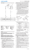
- Taper
- Manuel utilisateur

Date Issued: 09/28/17 IS-43995-CB
INSTRUCTIONS
For Assembling and Installing Fixtures in Canada
Pour L’assemblage et L’installation Au Canada
Nous sommes là pour vous aider 866-558-5706
Heures : du lundi au vendredi, de 9h à 17h (heure de l’Est)
ATTENTION – RISQUE DE DÉCHARGES ÉLECTRIQUES -
Couper le courant au niveau du panneau du disjoncteur du
circuit principal ou de la boîte à fusibles principale avant de
procéder à l’installation.
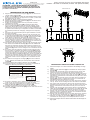
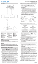
LOOP/LINK/LINK MOUNT
1) Follow steps 1 - 7 from Rigid Stem Mount Instructions.
2) Thread one small threaded pipe[7] into end of each small
loop[19].
3) Pass xture wire through rst loop. Thread one rst loop onto
end of each last stem.
4) On one side of xture, pass xture wire through second loop
and through hole in canopy[8]. Pass threaded pipe at end of
second loop through hole in canopy.
5) Pass xture wire through hole in lockwasher[9]. Thread
lockwasher onto end of threaded pipe protruding from inside
canopy.
6) Pass xture wire through hole in hexnut[10]. Thread hexnut
onto end of threaded pipe.
7) On other side of xture, pass xture wire through second loop
and through hole in canopy. Pass threaded pipe at end of sec-
ond loop through hole in canopy.
8) Pass xture wire through loop on end of safety cable[11]. Slip
loop on safety cable over end of threaded pipe protruding from
inside of canopy.
9) Pass xture wire through hole in lockwasher. Thread lockwash-
er onto end of threaded pipe protruding from inside canopy.
10) Pass xture wire through hole in hexnut. Thread hexnut onto
end of threaded pipe.
11) Attach locking link[20] to small loop at end of each stem and to
each loop on canopy.
12) Follow steps 12 - 20 from Rigid Stem Mount Instructions.
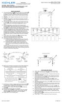
RIGID STEM MOUNT
1) Align a hole of a support arm [1] with a hole on a corner of the
lower frame [2].
2) Thread a nial [3] in from the bottom of the lower frame into
the hole. Tighten to secure the support arm to the frame. (The
arm should be ush with the frame).
3) Repeat steps 1-2 for the remaining arms.
4) Align the holes of the upper frame [4] with the holes on the top
of the support arms.
5) Thread the nials into the holes to secure the upper frame to
the arms.
6) Pass wire through stems[5] and screw stems into couplings[6]
on top of xture body. NOTE: 12.00” (Minimum) Stems are
required for mounting. NOTE: Thread locking compound must
be applied to all stem threads as noted with arrow symbol to
prevent accidental rotation of xture during cleaning, relamp-
ing, etc.
7) Pass xture wire through remaining stems and screw stems
together.
8) On each side of xture, pass xture wire through one small
threaded pipe[7]. Screw each small threaded pipe onto top of
stem on each side.
9) On each side of xture, pass xture wires through each hole
in canopy[8]. Lower canopy down towards stems. Pass each
hole in canopy over end of each threaded pipe on top of
stems.
10) On one side of xture, pass xture wire through hole in
lockwasher[9]. Thread lockwasher onto end of threaded pipe
protruding from inside canopy. Pass xture wire through hole in
hexnut[10]. Thread hexnut onto end of threaded pipe.
11) On other side of xture, pass xture wire through loop on
end of safety cable[11]. Slip loop on safety cable over end of
threaded pipe protruding from inside of canopy. Pass xture
wire through hole in lockwasher. Thread lockwasher onto end
of threaded pipe protruding from inside canopy. Pass xture
wire through hole in hexnut. Thread hexnut onto end of thread-
ed pipe.
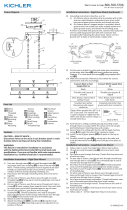
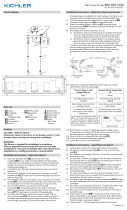
12) Find the appropriate threaded holes on mounting strap[12].
Assemble mounting screws [13] into threaded holes
13) Attach mounting strap to the outlet box [14].
14) Grounding instructions: (See Illus. A or B).
A) On xtures where mounting strap is provided with a hole
and two raise dimples. Wrap ground wire from outlet box
around green ground screw, and thread into hole.
B) On xtures where a cupped washer is provided. Put
ground wire from outlet box under cupped washer and
green ground screw and thread screw into hole in mount-
ing strap.
If xture is provided with ground wire. Connect xture ground
wire to outlet box ground wire with wire connector, (not provid-
ed) after following the above steps. Never connect ground wire
to black or white power supply wires.
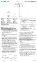
15) Make wire connections. Reference chart below for correct
connections and wire accordingly.
16) Push xture to ceiling, carefully passing mounting screws
through holes in canopy. NOTE: Be certain wires do not get
pinched between mounting strap and canopy.
17) Secure xture to ceiling with lockwashers[15] and lock-up
knobs[16].
18) Insert recommended bulbs (not supplied).
19) Carefully lower glass shade[17] over the bulb and onto the
glass holder [18].
GREEN GROUND
SCREW
CUPPED
WASHER
OUTLET BOX
GROUND
FIXTURE
GROUND
DIMPLES
WIRE CONNECTOR
OUTLET BOX
GROUND
GREEN GROUND
SCREW
FIXTURE
GROUND
A
B
Connect Black or
Red Supply Wire to:
Connect
White Supply Wire to:
Black White
*Parallel cord (round & smooth)
*Parallel cord (square & ridged)
Clear, Brown, Gold or Black
without tracer
Clear, Brown, Gold or Black
with tracer
Insulated wire (other than green)
with copper conductor
Insulated wire (other than green)
with silver conductor
*Note: When parallel wires (SPT I & SPT II)
are used. The neutral wire is square shaped
or ridged and the other wire will be round in
shape or smooth (see illus.)
Neutral Wire
►
►
►
►
►
►
►
►
1
2
3
4
5
6
8
►
► ►
►
LOOP/LINK/LOOP MOUNT
RIGID STEM MOUNT
7
11
9
10
12
13
14
15
16
17
18
7
19
8
9
10
12
13
14
11
20
►
►
►
►
►
►
►
►
1
2
3
4
5
6
8
►
► ►
►
LOOP/LINK/LOOP MOUNT
RIGID STEM MOUNT
7
11
9
10
12
13
14
15
16
17
18
7
19
8
9
10
12
13
14
11
20
►
►
►
►
►
►
►
►
1
2
3
4
5
6
8
►
► ►
►
LOOP/LINK/LOOP MOUNT
RIGID STEM MOUNT
7
11
9
10
12
13
14
15
16
17
18
7
19
8
9
10
12
13
14
11
20

Date Issued: 09/28/17 IS-43995-CB
INSTRUCTIONS
For Assembling and Installing Fixtures in Canada
Pour L’assemblage et L’installation Au Canada
Nous sommes là pour vous aider 866-558-5706
Heures : du lundi au vendredi, de 9h à 17h (heure de l’Est)
ATTENTION – RISQUE DE DÉCHARGES ÉLECTRIQUES -
Couper le courant au niveau du panneau du disjoncteur du
circuit principal ou de la boîte à fusibles principale avant de
procéder à l’installation.
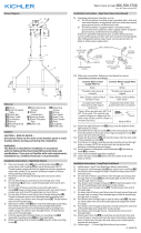
MONTAGE AVEC UNE BOUCLE/MAILLON/MAILLON
1) Suivre les étapes 1 à 7 des instructions de Montage sur tige
rigide.
2) Visserunpetittubeleté[7]surl’extrémitédechaquepetite
boucle [19].
3) Passerlelduluminaireparlapremièreboucle.Visserune
premièrebouclesurl’extrémitédechaquedernièretige.
4) Surundescôtésduluminaire,passerlelduluminaireparla
deuxièmebouclepuisparletroudanslecache[8]. Passer le
tubeletéàl’extrémitédeladeuxièmeboucleparletrousitué
danslecache.
5) Passerlelduluminaireparletrousituédanslarondellede
blocage [9].Visserlarondelledeblocagesurl’extrémitédu
tubeletésortantdel’intérieurducache.
6) Passerlelduluminaireparletrousituédansl’écrouhexago-
nal10].Visserl’écrouhexagonalsurl’extrémitédutubeleté.
7) Surl’autrecôtéduluminaire,passerlelduluminaireparla
deuxièmebouclepuisparletroudanslecache.Passerletube
letéàl’extrémitédeladeuxièmeboucleparletroudansle
cache.
8) Passerlelduluminaireparlabouclesituéeàl’extrémitédu
câble de sécurité [11]. Passer une boucle sur câble de sécurité
surl’extrémitédutubeletésortantdel’intérieurducache.
9) Passerlelduluminaireparletrousituédanslarondellede
blocage.Visserlarondelledeblocagesurl’extrémitédutube
letésortantdel’intérieurducache.
10) Passerlelduluminaireparletrousituédansl’écrouhexago-
nal.Visserl’écrouhexagonalsurl’extrémitédutubeleté.
11) Attacherunmaillondeverrouillage[20] à une petite boucle à
l’extrémitédechaquetigeetsurchaqueboucleducache.
12) Suivre les étapes de 12 à 18 des instructions de Montage sur
tige rigide.
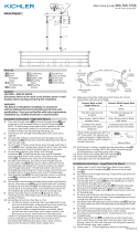
MONTAGE DE LA TIGE RIGIDE
1) Alignezuntroud’unbrasdesupport[1] avec un trou sur un
coin du cadre inférieur [2].
2) Enlerunnial[3] dans le bas du cadre inférieur dans le trou.
Serrerpourxerlebrasdesupportsurlecadre.(Lebrasdoit
être aligné avec le cadre).
3) Répétez les étapes 1-2 pour les bras restants.
4) Alignez les trous du cadre supérieur [4] avec les trous sur le
dessus des bras de support.
5) Enlezlesextrémitésdanslestrouspourxerlecadre
supérieur sur les bras.
6) Acheminerlelparlestiges[5] et visser les tiges dans
lesaccouplements[6]enhautduluminaire.NOTE:12.00”
(Minimum)Stemsarerequiredformounting.REMARQUE:
Appliquerlefreinletsurtouslesletsdelatigeindiquéspar
lesymboledelaèchepourempêcherlarotationaccidentelle
duluminairependantlenettoyage,changementd’ampoule,
etc.
7) Acheminerlelduluminaireparlestigesrestantesetvisser
lestigesensemble.
8) Dechaquecôtéduluminaire,passerunlduluminairepar
unpetittuyauleté[7].Vissertouslespetitstubesletéssur
ledessusdelatigedechaquecôté[8]. Visser tous les petits
tubesletéssurledessusdelatigedechaquecôté.
9) Dechaquecôtéduluminaire,passerleslsduluminaireà
traverschaquetroudanslecache[4].Abaisserlecachesur
lestiges.Passerchaquetroudanslecachesurl’extrémitéde
chaquetubeletésituéau-dessusdestiges.
10) Dechaquecôtéduluminaire,passerunlduluminaireparle
trou dans une rondelle de blocage [5]. Visser la rondelle de
blocagesurl’extrémitédutubeletésortantdel’intérieurdu
cache.Passerlelduluminaireparletrousituédansl’écrou
hexagonal[6].Visserl’écrouhexagonalsurl’extrémitédutube
leté.
11) Surl’autrecôtéduluminaire,passerlelduluminaireparla
bouclesituéeàl’extrémitéducâbledesécurité[11]. Passer
unebouclesurcâbledesécuritésurl’extrémitédutubeleté
sortantdel’intérieurducache.Passerlelduluminairepar
le trou situé dans la rondelle de blocage. Visser la rondelle de
blocagesurl’extrémitédutubeletésortantdel’intérieurdu
cache.Passerlelduluminaireparletrousituédansl’écrou
hexagonal.Visserl’écrouhexagonalsurl’extrémitédutube
leté.
12)Aucentredelasangledemontage[12]sontdesmachines
àsous.Retirezl’ensemblequicorrespondàvotreboîtede
sortie[13].
13)Fixezlasangledemontageàlaboîtedesortie[14].
14) Connecterlesls(connecteursnonfournis).Sereporterau
tableauci-dessouspourfairelesconnexions.
15) Pousserleluminaireversleplafondenpassantsoigneuse-
mentlesvisdemontageparlestrousdanslecache.
16) Fixerleluminairesécuritairementauplafondavecdesron-
delles de blocage [15]etboutonsdexation[16].
17) Installerlesampoulesrecommandées(nonfournies).
18) Carefullylowertheglassshade[17]overthebulbandontothe
glassholder[18].
Connecter le fil noir ou
rouge de la boite
Connecter le fil blanc de la boîte
A Noir A Blanc
*Au cordon parallèle (rond et lisse)
*Au cordon parallele (à angles droits el strié)
Au bransparent, doré, marron, ou
noir sans fil distinctif
Au transparent, doré, marron, ou
noir avec un til distinctif
Fil isolé (sauf fil vert) avec
conducteur en cuivre
Fil isolé (sauf fil vert) avec
conducteur en argent
*Remarque: Avec emploi d’un fil paralléle
(SPT I et SPT II). Le fil neutre est á angles
droits ou strié et l’autre fil doit étre rond ou
lisse (Voir le schéma).
Fil Neutre
►
►
►
►
►
►
►
►
1
2
3
4
5
6
8
►
► ►
►
LOOP/LINK/LOOP MOUNT
RIGID STEM MOUNT
7
11
9
10
12
13
14
15
16
17
18
7
19
8
9
10
12
13
14
11
20
►
►
►
►
►
►
►
►
1
2
3
4
5
6
8
►
► ►
►
LOOP/LINK/LOOP MOUNT
RIGID STEM MOUNT
7
11
9
10
12
13
14
15
16
17
18
7
19
8
9
10
12
13
14
11
20
►
►
►
►
►
►
►
►
1
2
3
4
5
6
8
►
► ►
►
LOOP/LINK/LOOP MOUNT
RIGID STEM MOUNT
7
11
9
10
12
13
14
15
16
17
18
7
19
8
9
10
12
13
14
11
20
-
 1
1
-
 2
2


Kichler Lighting 43995CH Manuel utilisateur
- Taper
- Manuel utilisateur
dans d''autres langues
- English: Kichler Lighting 43995CH User manual
Documents connexes
-
 Kichler Lighting 44082BK Manuel utilisateur
-
 Kichler Lighting 44340WNWLED Manuel utilisateur
-
 Kichler Lighting 44250NI Manuel utilisateur
-
 Kichler Lighting 44296WWW Manuel utilisateur
-
 Kichler Lighting 44043AUB Manuel utilisateur
-
 Kichler Lighting 44038NI Manuel utilisateur
-
 Kichler Lighting 44285WWW Manuel utilisateur
-
 Kichler Lighting 44180BKT Manuel utilisateur
-
 Kichler Lighting 43595BK Manuel utilisateur
-
 Kichler Lighting 44222BK Manuel utilisateur


