Lifetime 71524 Le manuel du propriétaire
- Taper
- Le manuel du propriétaire
La page est en cours de chargement...

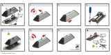
• Préparez le coin
Avant de commencer, déterminez comment vous
souhaitez remplir la base (nous recommendons
le sable, voyez la page 33).
• Rassemblez vos amis et votre famille
L’assemblage devrait prendre 2 adultes à peut
près 2 – 3 heures.
For English, see page 1. Para el español, ver la página 3.
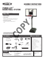
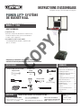
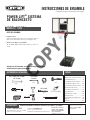
INSTRUCTIONS D’ASSEMBLAGE
MODEL #60091
MODÈLE n° 71524
OUTILS REQUIS SOMMAIRE
Concervez ces instructions au cas ou vous avez besoin de
contacter le fabricant pour obtenir des pièces de remplacement.
AVANT L’ASSEMBLAGE :
CONTACTEZ AUX SERVICES À LA CLIENTÈLE LIFETIME
®
:
Composer le 1-800-225-3865
Du lundi au vendredi 7:00 hr – 17:00 hr (HNR)
et samedi 9:00 hr – 13:00 hr (HNR)
t’Chat en direct: www.lifetime.com
(cliquer sur la languette « Ask An Expert »)
Videos educatifs: www.youtube.com/lifetimeproducts
QUESTIONS ?
N° DE MODÈLE ET RÉFÉRENCE DU
PRODUIT (vous aurez besoin des deux lorsque
vous nous contactez)
N° de modèle : 71524
Référence du produit :
Pour nos services à la clientèle du
continent européen et au Royaume-Uni,
E-mail : [email protected]
POWER LIFT
®
SYSTÈME
DE BASKET-BALL
(x2)
(x1)
(x1)
(x1)
(x1)
(x1)
(x1)
1/2"/po (13 mm), 9/16"/po (14 mm),
3/4"/po (19 mm)
3/16"/po (5 mm)
(inclus)
(375 lb)/(170kg)
Légende des icônes.......................4
Avertissements et Notifi cations......5
Assemblage du poteau...................6
Assemblage du poteau à la base...11
Assemblage du tableau à
l’anneau...................................15
Assemblage du tableau au poteau..21
Identifi cateur de pièces...............i-iv
Assemblage de la poignée............24
Assemblage fi nal.........................30
Déplacer le systèm......................36
Entretien..............................37
Autocollant d’avertissement.........38
Enregistrement.....................39
Garantie...............................42
1/2"/po (13 mm)
(x2)
(x1)
(x1)
(x1)
COPY
La page est en cours de chargement...
La page est en cours de chargement...

5
WARNINGS & NOTICES / AVERTISSEMENTS ET AVIS / ADVERTENCIAS Y AVISOS
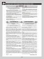
Most injuries are caused by misuse and/or not following instructions. Use caution when using this product.
To ensure safety, do not attempt to assemble this product without following the instructions carefully. Check entire box and inside all packing
material for parts and/or additional instruction material. Before beginning assembly, read the instructions and identify parts using the hardware
identifi er and parts list in this document. Proper and complete assembly, use and supervision are essential for proper operation and to reduce the
risk of accident or injury. A high probability of serious injury exists if this product is not installed, maintained, and operated properly.
FAILURE TO FOLLOW THESE WARNINGS MAY RESULT IN SERIOUS INJURY OR PROPERTY DAMAGE AND WILL VOID WARRANTY.
Owner must ensure that all players know and follow these rules for safe operation of the system.
• If using a ladder during assembly, use extreme caution.
• Two capable adults are recommended for this operation.
• Check base daily for leakage. Leaks will cause system to fall.
• Assemble the pole sections properly. Failure to do so could cause the pole sections to separate during play or transport.
• Minimum operational height is 6 ft 6 in (1.98m) to the bottom of the backboard.
SAFETY INSTRUCTIONS
La mayoría de las lesiones son causadas por el abuso y/o por el no seguir las instrucciones. Sea cauteloso al usar este producto.
Para su seguridad, no intente ensamblar este producto sin leer y seguir todas las instrucciones cuidadosamente. Revise la caja entera y todos los
materiales de embalaje en busca de piezas y / o material de instrucciones adicional. Antes de comenzar el ensamble, identifi que todas las piezas y el
equipo usando las listas de partes y equipo así como los identifi cadores en este documento. El ensamble correcto y completo, el uso y la supervisión
son esenciales para una orientación apropiada y para reducir el riesgo de un accidente o lesión. Existe una alta probabilidad de sufrir lesiones graves
si este producto no es instalado, mantenido y / o operado correctamente.
EL INCUMPLIMIENTO DE SEGUIR ESTAS ADVERTENCIAS PUEDE OCASIONAR EN LESIONES GRAVES Y/O DAÑO A LA PROPIEDAD Y ANULARÁ LA GARANTÍA.
El propietario debe asegurarse de que todos los jugadores conocen y seguir estas reglas para la operación segura del sistema.
• Si utiliza una escalera durante el ensamble, tenga mucho cuidado.
• Se recomienda la participación de dos adultos capaces para esta ensamble.
• Compruebe si hay fugas en la base. Las fugas pueden causar que el producto caiga.
• Ensamble las secciones del poste correctamente. De lo contrario, podría provocar que las secciones del poste se separaran
durante el juego o el transporte.
• Altura mínima de operación es 1,98m (6 ft 6 in) a la parte inferior del tablero.
INSTRUCCIONES DE SEGURIDAD
La majorité des accidents résultent d’une mauvaise utilisation et/ou du fait de n’avoir pas suivi les consignes. Observez toutes précautions utiles pendant
l’utilisation de ce produit.
Pour assurer votre sécurité, ne tentez pas d’assembler cet article sans avoir lu et suivi toutes les consignes attentivement. Vérifi ez la totalité de la
boîte et l’intérieur de tous les matériaux d’emballage pour trouver toutes les pièces et/ou matériau contenant des consignes supplémentaires. Avant
de commencer le montage, identifi ez toutes les pièces et tous les accessoires et faites-en l’inventaire en les comparant aux listes et identifi cateurs
de pièces et accessoires contenus dans ce document. Un assemblage correct et complet, ainsi que l’utilisation et la supervision correctes sont des
conditions essentielles à la bonne direction et diminuent les risques d’accident ou de blessure. Une haute probabilité d’accident grave résulte de
mauvaises conditions d’installation, maintenance et/ou utilisation.
LA NON-RESPECT DE CES AVERTISSEMENTS PEUT RÉSULTER EN ACCIDENTS GRAVES OU DOMMAGES MATÉRIELS ET ANNULER LA GARANTIE.
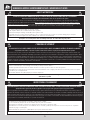
Le propriétaire doit veiller à ce que tous les joueurs connaissent et suivent ces règles pour une exploitation sûre du système.
• Agissez avec la plus grande prudence si vous employez une échelle pour l’assemblage.
• Il est recommandé que cet assemblage soit exécuté par deux personnes adultes.
• Vérifi ez quotidiennement la base au niveau de fuites. Les fuites peuvent causer la chute du système.
• Assemblez les sections de poteau correctement. La non-observation de cette consigne peut amener les sections de poteau à se séparer
pendant le jeu ou le déplacement.
• La hauteur minimale est 1,98 m (6 pi 6 po) au bas de la planche.
CONSIGNES DE SÉCURITÉ

6
BCO
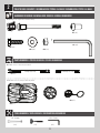
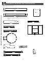
Metal Parts / Pièces en métal / Piezas de metal
Hardware Bag / Sac de quincailleries / Bolsa de herraje
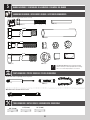
TOOLS REQUIRED / OUTILS REQUIS / INSTRUMENTAL REQUERIDO
PARTS REQUIRED / PIÈCES REQUISES / PIEZAS REQUERIDAS
HARDWARE REQUIRED / QUINCAILLERIES REQUIS / HERRAJE REQUERIDO
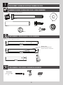
POLE ASSEMBLY / ASSEMBLAGE DU POTEAU / ENSAMBLE DEL POSTE
1
Warning Sticker
Autocollant d’avertissement
Etiqueta adhesiva de advertencia
ADS (x2)
ABZ (x2)
ABB (x2)
AAF (x2)
ABE (x2)
ABR (x2)
CIH (x2)
9/16" (14 mm)
(x2)
ALH (x1)
ALF (x1)
ALE (x1)
43 ”
3/8
43 ”
3/8
27 5/8”
(110 cm)
(110 cm)
(70 cm)
(x1)
(x1)
(x1)
ALL (x1)

7
TOOLS AND HARDWARE REQUIRED / OUTILS ET QUINCAILLERIES REQUIS / INSTRUMENTAL Y HERRAJE REQUERIDOS
X SECTION 1 (CONTINUED) / SECTION 1 (SUITE) / SECCIÓN 1 (CONTINUACIÓN)
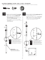
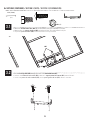
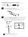
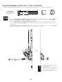
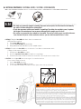
• Secure the Pole Bracket (ALL) to the Top Pole (ALH) with the hardware as shown.
• Attachez le Support de poteau (ALL) au Poteau supérieur (ALH) à l’aide des quincailleries illustrées.
• Sujete el Soporte de poste (ALL) al Poste superior (ALH) usando el herraje ilustrado.
1.1
Large Holes
Grands trous
Agujeros grandes
Small Holes
Petits trous
Agujeros pequeños
AAF (x2)
ABE (x2)
ABR (x2)
9/16" (14 mm)
ABB (x2)
ABE
AAF
ALH
ALH
ALL
ABB
ABE
ABR
(x2)

8
TOOLS AND HARDWARE REQUIRED / OUTILS ET QUINCAILLERIES REQUIS / INSTRUMENTAL Y HERRAJE REQUERIDOS
X SECTION 1 (CONTINUED) / SECTION 1 (SUITE) / SECCIÓN 1 (CONTINUACIÓN)
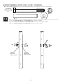
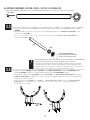
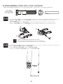
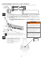
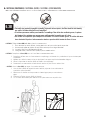
• Align the hole in the bottom of the Top Pole (ALH)
with the slot in the top of the Middle Pole (ALF).
• Alignez le trou dans la partie inférieure du
Poteau supérieur (ALH) avec la fente dans la partie
supérieure du Poteau du milieu (ALF).
• Alinee el agujero en la parte inferior del Poste
superior (ALH) con la ranura en la parte superior del
Poste intermedio (ALF).
• Secure the Middle Pole to the Bottom Pole (ALE) using
the same method as step 1.2.
• Attachez bien le Poteau du milieu au Poteau inférieur
(ALE) en utilisant le même méthode de l’étape 1.2.
• Sujete el Poste intermedio al Poste inferior (ALE)
usando el mismo método del paso 1.2.
1.2 1.3
!
• The Screw should be fl ush with the Pole,
but will spin freely once inserted.
• La Vis doit ser au ras du Poteau, mais elle
tournera librement une fois insérée.
• El Tornillo debe estar a ras del Poste, mas
girará libremente una vez insertado.
Warning Sticker
Autocollant d’avertissement
Etiqueta adhesiva de advertencia
!
• The Screw should be fl ush with the Pole,
but will spin freely once inserted.
• La Vis doit ser au ras du Poteau, mais
elle tournera librement une fois insérée.
• El Tornillo debe estar a ras del Poste,
mas girará libremente una vez insertado.
1.2
ADS (x2)
1.3
CIH (x2)
ALH
ALF
ADS
ADS
ALF
ALH
CIH
ALH
ALF
ALE
ALE
ALF
CIH
(x1)

9
TOOLS AND HARDWARE REQUIRED / OUTILS ET QUINCAILLERIES REQUIS / INSTRUMENTAL Y HERRAJE REQUERIDOS
X SECTION 1 (CONTINUED) / SECTION 1 (SUITE) / SECCIÓN 1 (CONTINUACIÓN)
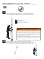
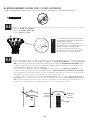
• Strike the end of the Pole Assembly on a piece of scrap wood or cardboard 5–6 times.
• Frappez l’extrémité de l’Assemblage du poteau sur une chute de bois ou carton 5–6 fois.
• Golpee el extremo del Ensamble del poste en una plaquita de madera o cartón 5–6 veces.
1.4
6x
• Do not strike your feet with the Pole sections, as
serious injury may occur.
• Ne pas se cogner les pieds avec les Sections du
poteau ; ceci peut causer des blessures graves.
• No golpee los pies con las Secciones del poste, ya
que esto puede ocasionarle graves lesiones.
!
• Flip the Pole over and repeat step 1.4 for the opposite end of the Pole Assembly.
• Renversez le Poteau, et répétez l’étape 1.4 pour l’extrémité opposée de l’Assemblage du poteau.
• Dé la vuelta el Poste, y repita el paso 1.4 para el extremo opuesto del Ensamble del poste.
1.5
6x
(x1)
WARNING / AVERTISSEMENT / ADVERTENCIA
The Poles must be seated together! Even if the Poles cover the slots before seating, they must
be struck on a hard surface five to six times! Failure to seat the Poles correctly could allow the
Poles to separate during use, which could lead to serious personal injuries or property damage.
¡Los postes deben quedar asentados de manera conjunta! Incluso si los postes cubren las ranuras
antes de quedar asentados, ¡deben ser golpeados sobre una superficie dura de cinco a seis
veces! Si no se asientan correctamente los postes, eso podría permitir que los postes se separen
durante el uso, lo que podría provocar graves lesiones personales o daños a la propiedad.
Les poteaux doivent s’enclencher les uns les autres! Même si les poteaux recouvrent les
fentes avant de s’enclencher, vous devez les frapper sur un morceau de bois cinq à six fois!
Un mauvais enclenchement des poteaux peut entraîner leur séparation lors de l’utilisation, et
causer des blessures graves et endommager matériel.
!

10
TOOLS AND HARDWARE REQUIRED / OUTILS ET QUINCAILLERIES REQUIS / INSTRUMENTAL Y HERRAJE REQUERIDOS
X SECTION 1 (CONTINUED) / SECTION 1 (SUITE) / SECCIÓN 1 (CONTINUACIÓN)
• Secure the poles together with Self-drilling Screws (ABZ).
• Attachez les Poteaux l’un à l’autre à l’aide des Vis autotaraudeuses (ABZ).
• Sujete los Postes el uno al otro con Tornillos autoroscantes (ABZ).
1.6
ABZ (x2)
• For ease of installation, chuck the Self-Drilling
Screws directly into the drill, or use a 3/8" (10 mm)
Hex Driver.
• Pour faciliter l’installation, mettez les Vis
autotaraudeuses directlement dans la Perceuse, ou
utilisez un tournevis à écrou de 3/8 po (10 mm).
• Para facilitar la instalación, fi je los Tornillos
autoroscantes directamente en el taladro, o use una
llave de tuerca de 3/8" (10 mm).
!
ABZ
ABZ
(x1)

11
POLE TO BASE ASSEMBLY / ASSEMBLAGE DU POTEAU A LA BASE / ENSAMBLE DEL POSTE A LA BASE
2
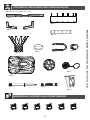
BCQ
Metal Parts / Pièces en métal / Piezas de metal
Hardware Bag / Sac de quincaillerie / Bolsa de herraje
TOOLS REQUIRED / OUTILS REQUIS / INSTRUMENTAL REQUERIDO
PARTS REQUIRED / PIÈCES REQUISES / PIEZAS REQUERIDAS
HARDWARE REQUIRED / QUINCAILLERIE REQUISE / HERRAJE REQUERIDO
AAE (x2)
BTS (x1)
ABD (x4)
AAO (x2)
EEO (x2)
AMU (x2)
AJM (x1)
Plastic Parts / Pièces en plastique / Piezas de plástico
(x2) (x1)
3/16” (5 mm)
(x2)
21 3/4 ”
AJD (x1)
ALI (x2)
AJN (x1)
38”
DRZ (x1)
1/2” (13 mm)
38 in/po (96,5 cm)
21 3/4 in/po (55,3 cm)
CCL (x2)

12
TOOLS AND HARDWARE REQUIRED / OUTILS ET QUINCAILLERIE REQUIS / INSTRUMENTAL Y HERRAJE REQUERIDOS
X SECTION 2 (CONTINUED) / SECTION 2 (SUITE) / SECCIÓN 2 (CONTINUACIÓN)
2.1
• Make sure the rubber gasket is inside
the Base Cap.
• Assurez-vous que le joint en
caoutchouc est dans le capuchon.
• Asegúrese que la tapa de goma
está dentro del tapón.
AJM
AJN
AJN
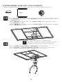
• Screw the Base Cap (AJN) onto the Base (AJM) as shown.
• Attachez le Capuchon (AJN) à la Base (AJM) comme illustrée.
• Atornille el Tapón (AJN) a la Base (AJM) como se muestra.
!
2.2
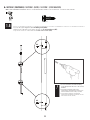
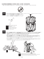
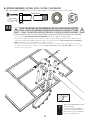
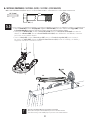
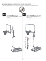
• Slide the Axle (AJD) through one of the Wheels (AMU) and into the Base as shown. Then have one adult position the Bottom
Pole (ALE) within the Base as shown with the lip at the bottom of the pole facing outward. Finally, insert the Axle through the
Bottom Pole and into the other side of the Base and through the other Wheel.
• Glissez l’essieu (AJD) à travers une des roues (AMU) et dans la Base comme illustré. Ensuite, un adulte doit positionner le
Poteau inférieur (ALE) dans la base comme illustré avec le côté cabossé à l’extrémité indérieure du poteau vers l’extérieur. Insérez
l’essieu à travers le poteau inférieur et dedans l’autre côté de la base et à travers l’autre roue.
• Deslice el eje (AJD) por una de las ruedas (AMU) y dentro de la Base como se muestra. Entonces, un adulte debe ubicar el
Poste inferior (ALE) dentro de la base como se muestra con el lado abollado del poste inferior hacia afuera. Por último, inserte el
eje por el poste inferior y dentro del otro lado de la base y a través de la otra rueda.
• It may be necessary to use a rubber mallet to tap the Axle into place.
• Il peut-être nécessaire d’utiliser un maillet en caoutchouc pour frapper l’essieu en place.
• Tal vez sea necesario usar un mazo de goma para tapar el eje en su lugar.
AJD
AMU
AMU
ALE
!

13
TOOLS AND HARDWARE REQUIRED / OUTILS ET QUINCAILLERIE REQUIS / INSTRUMENTAL Y HERRAJE REQUERIDOS
X SECTION 2 (CONTINUED) / SECTION 2 (SUITE) / SECCIÓN 2 (CONTINUACIÓN)
2.3
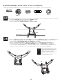
• Attach the fl attened end of the Pole Brace (ALI) to the Base with the hardware shown. Only fi nger tighten the hardware.
• Attachez l’extrémité plate du Support du poteau (ALI) à la Base à l’aide de la quincaillerie illustrée. Ne serrez la
quincaillerie qu’à la main.
• Sujete el extremo aplanado del Soporte del poste (ALI) a la Base usando el herraje indicado. Apriete el herraje sólo a mano.
• Repeat this step to install the other Pole Brace to the other side of the Base.
• Répétez cette étape pour installer l’autre support du poteau sur l’autre
côté de la base.
• Repita este paso para instalar el otro soporte del poste en el otro lado de
la base.
!
ALI
AAE
ABD
ABD
AAO
AAE (x2)
ABD (x4)
AAO (x2)
(x1)

14
TOOLS AND HARDWARE REQUIRED / OUTILS ET QUINCAILLERIE REQUIS / INSTRUMENTAL Y HERRAJE REQUERIDOS
X SECTION 2 (CONTINUED) / SECTION 2 (SUITE) / SECCIÓN 2 (CONTINUACIÓN)
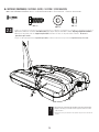
• Tip the system forward and rest the Pole on the ground. Do not stand the system up until it is fi lled with either sand or water later in
the assembly. Tighten the hardware shown.
• Faites basculer le système en avant et posez le poteau sur la terre. Ne remettez pas le système à la verticale jusqu’à ce qu’il soit
rempli d’eau ou de sable plus tard dans l’assemblage. Serrez la quincaillerie illustrée.
• Incline el sistema hacia delante y coloque el poste en el suelo. No ponga vertical el sistema hasta llenarlo con agua o arena más
tarde en el ensamble. Apriete el herraje indicado.
2.5
2.4
• Attach the Pole Braces (ALI) to the Bottom Pole (ALE) with the hardware shown.
• Attachez les Supports du poteau (ALI) au Poteau inférieur (ALE) à l’aide de la quincaillerie illustruée.
• Sujete los Soportes del poste (ALI) al Poste inferior (ALE) usando el herraje indicado.
3/16” (5 mm)
DRZ (x1)
BTS (x1)
(x2)
BTS
DRZ
ALE
ALI
ALI
1/2” (13 mm)
(x2)

15
3
AOW (x1)
AOU (x1)
AJW (x2)
ABK (x4)
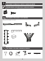
BACKBOARD TO RIM ASSEMBLY / ASSEMBLAGE DU TABLEAU À L’ANNEAU / ENSAMBLE DEL TABLERO AL ARO
HARDWARE REQUIRED / HERRAJE REQUERIDO / QUINCAILLERIE REQUISE
Hardware Bag / Sac de quincaillerie / Bolsa de herraje
AAQ (x2)
APY (x1)
EAP (x2)
ADR (x4)
ABQ (x1)
PARTS REQUIRED / PIÈCES REQUISES / PIEZAS REQUERIDAS
Metal Parts / Pièces en métal / Piezas de metal
ALX (x1)
AMA (x1)
AJI (x1)
Plastic Parts / Pièces en plastique / Piezas de plástico
ALD (x1)
BCS
TOOLS REQUIRED / OUTILS REQUIS / HERRAMIENTAS REQUERIDAS
(x1)
9/16" (14 mm)
(x2)
1/2" (13 mm)
(x1)
AMY (x2)
DFD (x1)
ABB (x4)
DFE (x4)
AAV (x2)

16
X SECTION 3 (CONTINUED) / SECTION 3 (SUITE) / SECCIÓN 3 (CONTINUACIÓN)
TOOLS AND HARDWARE REQUIRED / OUTILS ET QUINCAILLERIE REQUIS / INSTRUMENTAL Y HERRAJE REQUERIDOS
3.1
3.2
9/16" (11 mm)
(x2)
• Attach the Backboard Brackets (AMY) to the Backboard using the hardware indicated.
• Attachez bien les supports du tableau (AMY) au tableau à l’aide de la quincaillerie indiquée.
• Sujete los soportes del tablero (AMY) al tablero usando el herraje indicado.
ABB
DFE
DFE
DFE
DFE
ABB
AMY
• Insert two Carriage Bolts (EAP) through each hole in the Rim Pivot Bracket (APY).
• Insérez deux boulons de carrosserie (EAP) à travers le support pivotant de l’anneau (APY) comme illustré.
• Inserte dos pernos de cuello cuadrado (EAP) por el soporte giratorio del aro (APY) como se muestra.
EAP
APY
EAP
EAP (x2)
APY (x1)
DFE (x4)
ABB (x4)

17
X SECTION 3 (CONTINUED) / SECTION 3 (SUITE) / SECCIÓN 3 (CONTINUACIÓN)
TOOLS AND HARDWARE REQUIRED / OUTILS ET QUINCAILLERIE REQUIS / INSTRUMENTAL Y HERRAJE REQUERIDOS
3.3
3.4
1/2" (13mm)
(x1)
AAQ (x2)
ABQ (x1)
• Use the 1/2" (13 mm) socket head from the socket head wrench to press one Push Nut (AAQ) onto one end of the
Axle (ABQ).
• Utilisez la douille de 13 mm (1/2"/ po) de la clé à douille pour pousser une rondelle de retenue (AAQ) sur une
extrémité de l’essieu (ABQ).
• Use el cubo de 13 mm (1/2") de la llave de cubo para presionar una rondana de fi jación rápida (AAQ) sur un
extremo del eje (ABQ).
AAQ
ABQ
• The Push Nut (AAQ) should rest about 1/4" (6 mm) from the end of the Axle (ABQ). If the Push Nut (AAQ) slips
on too far, continue sliding it to the other end of the Axle (ABQ) to remove it and try again.
• La rondelle de retunue doit rester environ 6,35 mm (1/4 po) de l’extrémité de l’essieu. Si la rondelle de
retenue glisse plus de cela, faites-le glisser de l’autre extrémité de l’essieu et commencez de nouveau.
• La rondana de fi jación rápida debe quedarse 6,35 mm (1/4 in) del extremo del eje. Si la rondana de fi jación
rápida se resbala más que eso, resbálela del otro extremo del eje y empiece de nuevo.
!
!
• Slide the end of the Axle (ABQ) through the Rim (ALX) and the Rim Pivot Bracket (APY). Press the Push Nut (AAQ) onto the
end of the Axle (ABQ). Use the 1/2" (13 mm) socket head to secure the Push Nut (AAQ) if needed.
• Faites glisser l’extrémité de l’essieu (ABQ) à travers l’anneau (ALX) et le support pivotant de l’anneau (APY). Poussez la
rondelle de retenue (AAQ) sur l’extrémité de l’essieu. Si besoin, employez la douille de 13 mm (1/2 po) pour fi xer
la rondelle de retenue en place.
• Deslice el extremo del eje (ABQ) por el aro (ALX) y el soporte giratorio del aro (APY). Presione la rondana de fi jación
rápida (AAQ) sobre el extremo del eje. Si hace falta, use el cubo de 13 mm (1/2") para fi jar la rondana de
fi jación rápida en su lugar.
AAQ
ABQ
APY
ALX
ABQ
1/2" (13 mm) Socket Head
13 mm (1/2 po) de la clé à douille
13 mm (1/2") de la llave de cubo

18
X SECTION 3 (CONTINUED) / SECTION 3 (SUITE) / SECCIÓN 3 (CONTINUACIÓN)
TOOLS AND HARDWARE REQUIRED / OUTILS ET QUINCAILLERIE REQUIS / INSTRUMENTAL Y HERRAJE REQUERIDOS
3.5
(x1)
3.6
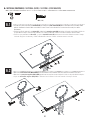
• Lay the Backboard (AJI) on a table or bench. Insert the U-Bolt (AOU) through the upper part of the opening on the backside of
the Backboard (AJI) as shown.
• Mettez le panneau (AJI) sur une table ou un banc. Insérez le Boulon en « U » (AOU) à travers le partie supérieure du trou au
verso du Panneau (AJI) comme illustré.
• Coloque el tablero (AJI) sobre una mesa o un banco. Inserte el Perno en «U» (AOU) por la parte superior del hueco en la parte
trasera del Tablero (AJI) como se muestra.
• Insert the U-Bolt (AOU) through the top holes of the Backboard and the Rim.
• Insérez le Boulon en « U » (AOU) à travers le jeu supérieur des trous du Panneau et de l’Anneau.
• Inserte el Perno em«U» (AOU) a través de los agujeros superiores del Tablero y del Aro.
!
!
1/2" (13mm)
AOU (x1)
AOU
DFD
• Connect the Rim (ALX) and Plastic Guard (ALD) to the Backboard (AJI) with the hardware shown.
• Attachez l’Anneau (ALX) et le Protection en plastique (ALD) au Panneau (AJI) en utilisant les accessoires indiqués.
• Sujete el Aro (ALX) y la Protección de plastico (ALD) al Tablero (AJI) usando el herraje indicado.
ALX
ALD
AJI
ABK
AOU
EAP
ABK (x2)
ABK
EAP

19
X SECTION 3 (CONTINUED) / SECTION 3 (SUITE) / SECCIÓN 3 (CONTINUACIÓN)
TOOLS AND HARDWARE REQUIRED / OUTILS ET QUINCAILLERIE REQUIS / INSTRUMENTAL Y HERRAJE REQUERIDOS
3.7
ABK (x2)
3.8
1/2" (13 mm)
• Thread the Jam Nuts (AAV) all the way down on the U-Bolt (AOU) as shown.
• Serrez bien les Contre-écrous (AAV) au Boulon en « U » (AOU).
• Apriete por completo las Contratuercas de (AAV) en el Perno en «U» (AOU).
(x1)
AAV
AOU
AOU
• Slide the Compression Springs (AJW) onto the U-Bolt (AOU), and place the Spring Retainer Plate (AOW) over the Compression
Springs. Tighten the Nylock Flange Nuts (ABK) until the Rim (ALX) does not wobble.
• Glissez les Ressorts de pression (AJW) sur le Boulon en « U » (AOU), et placez the Plaque de retenue du ressort (AOW) sur les
Ressorts de pression. Serrez bien les Écrous à bride en nylon (ABK) jusqu’à ce que l’Anneau (ALX) n’est pas branlant.
• Deslice los Resortes de compresión (AJW) sobre el Perno en «U» (AOU), y coloque la Placa retenedor del resorte (AOW) sobre los
Resortes de compresión. Apriete las Tuercas de brida de nailon hasta que no se bambolea el Aro (ALX).
• Do not completely tighten the Nuts in this step!
Tightening the Nuts adjusts the Rim Tension.
• Ne pas serrer excessivement les Écrous pour que
les Écrous en caoutchouc se gonfl ent.
• No apriete demasiado las Tuercas para que se
sobresalgan las Tuercas de goma.
!
AJW
ABK
ABK
AOW
AOU
AJW (x2)
AOW (x1)
AAV (x2)

20
X SECTION 3 (CONTINUED) / SECTION 3 (SUITE) / SECCIÓN 3 (CONTINUACIÓN)
TOOLS AND HARDWARE REQUIRED / OUTILS ET QUINCAILLERIE REQUIS / INSTRUMENTAL Y HERRAJE REQUERIDOS
• Attach the Rim Cover Plate (AMA) to the Rim using Screws (ADR).
• Attachez bien la plaque protectrice des ressorts (AMA) à l’anneau (ALX) à l’aide de la quincaillerie indiquée.
• Sujete la placa protectora de los resortes (AMA) al aro (ALX) usando el herraje indicado.
ADR
AMA
3.9
ADR (x4)

21
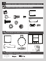
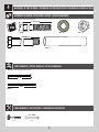
BCR
Metal Part / Pièce en métal / Pieza de metal
Hardware Bag / Sac d’accessoires / Bolsa de herraje
TOOLS REQUIRED / OUTILS REQUIS / INSTRUMENTAL REQUERIDO
PARTS REQUIRED / PIÈCES REQUISES / PIEZAS REQUERIDAS
HARDWARE REQUIRED / ACCESSOIRES REQUIS / HERRAJE REQUERIDO
(x2)
3/4" (19mm)
(x1)
AAX (x4)
ABN (x8)
AAD (x2)
7 1/16”
AKC (x2)
AKB (x2)
21 1/8”
7 1/16" (18 cm)
DGA (x2)
7 1/2" (19 cm)
DFB (x2)
BACKBOARD TO POLE ASSEMBLY / ASSEMBLAGE DU TABLEAU AU POTEAU / ENSAMBLE DEL TABLERO AL POSTE
4
25 7/8”

22
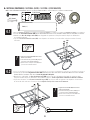
TOOLS AND HARDWARE REQUIRED / OUTILS ET ACCESSOIRES REQUIS / INSTRUMENTAL Y HERRAJE REQUERIDOS
X SECTION 4 (CONTINUED) / SECTION 4 (SUITE) / SECCIÓN 4 (CONTINUACIÓN)
3/4" (19 mm)
AAX (x2)
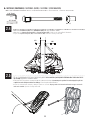
• Secure the Short Extension Arms (AKC) to the Backboard Brackets in the location shown with the hardware indicated.
• Attachez les Bras de rallonge courts (AKC) aux Supports du panneau à l’emplacement indiqué en utilisant les
accessoires indiqués.
• Sujete los Brazos de extensión cortos (AKC) a los Soportes del tablero en la ubicación indicada usando el herraje
indicado.
AAX
DGA
DFB
ABN
AKC
• Tighten the Centerlock Nut (AAX) until it is fl ush
with the end of the Bolt.
• Serrez l’Écrou de blocage central (AAX) jusqu’à ce
qu’il soit au ras de l’extrémité du Boulon.
• Apriete la Tuerca de bloqueo central (AAX) hasta
que esté a ras del extremo del Perno.
!
4.1
(x2)
(x1)
4.2
• Tighten the Centerlock Nut (AAX) until it is fl ush
with the end of the Bolt.
• Serrez l’Écrou de blocage central (AAX) jusqu’à
ce qu’il soit au ras de l’extrémité du Boulon..
• Apriete la Tuerca de bloqueo central (AAX) hasta
que esté a ras del extremo del Perno.
!
AKC
ABN
DFB (x2)
7 1/2" (19 cm)
ABN (x4)
DFB
AKB
AKB
ABN
AAX
ABN
DGA
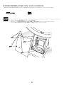
• Secure the ends of the Long Extension Arms (AKB) that only have one hole to the Backboard Brackets in the location
shown with the hardware indicated. Secure only by hand at this point.
• Attachez les extrémités des Bras de rallonge longs (AKB) qui n’a qu’un seul trou aux Supports de panneau dans
l’emplacement indiqué en utilisant les accessoires indiqués. Serrez la quincaillerie seulement à la main en ce moment.
• Sujete los extremos de los Brazos de extensión largos (AKB) que tienen sólo un agujero a los Soportes de tablero en
la ubicación indicada con el herraje indicado Apriete el herraje sólo a mano en este momento.
DGA (x2)
AKB

i
PARTS IDENTIFIER / IDENTI
-
FICADOR DE PIEZAS / IDEN-
TIFICATEUR DE PIÈCES
PARTS IDENTIFIER / IDENTIFICATEUR DE PIÈCES / IDENTIFICADOR DE PIEZAS
This page intentionally left blank
Cette page est intentionnellement laissée en blanc
Esta página ha sido dejada en blanco intencionalmente
Remove This Section / Enlevez Cette Section / Reitire Esta Sección
La page est en cours de chargement...
La page est en cours de chargement...
La page est en cours de chargement...
La page est en cours de chargement...
La page est en cours de chargement...
La page est en cours de chargement...
La page est en cours de chargement...
La page est en cours de chargement...
La page est en cours de chargement...
La page est en cours de chargement...
La page est en cours de chargement...
La page est en cours de chargement...
La page est en cours de chargement...
La page est en cours de chargement...
La page est en cours de chargement...
La page est en cours de chargement...
La page est en cours de chargement...
La page est en cours de chargement...
La page est en cours de chargement...
La page est en cours de chargement...
La page est en cours de chargement...
La page est en cours de chargement...
La page est en cours de chargement...
La page est en cours de chargement...
La page est en cours de chargement...
-
 1
1
-
 2
2
-
 3
3
-
 4
4
-
 5
5
-
 6
6
-
 7
7
-
 8
8
-
 9
9
-
 10
10
-
 11
11
-
 12
12
-
 13
13
-
 14
14
-
 15
15
-
 16
16
-
 17
17
-
 18
18
-
 19
19
-
 20
20
-
 21
21
-
 22
22
-
 23
23
-
 24
24
-
 25
25
-
 26
26
-
 27
27
-
 28
28
-
 29
29
-
 30
30
-
 31
31
-
 32
32
-
 33
33
-
 34
34
-
 35
35
-
 36
36
-
 37
37
-
 38
38
-
 39
39
-
 40
40
-
 41
41
-
 42
42
-
 43
43
-
 44
44
-
 45
45
-
 46
46
-
 47
47
-
 48
48


Lifetime 71524 Le manuel du propriétaire
- Taper
- Le manuel du propriétaire
dans d''autres langues
- English: Lifetime 71524 Owner's manual
- español: Lifetime 71524 El manual del propietario
Documents connexes
-
Lifetime 71524 Le manuel du propriétaire
-
-
Lifetime 71525 Le manuel du propriétaire
-
-
-
-
-
-
-