
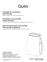
Portable Air Conditioner - User Manual
Models:
IPAC06-DR (Black, 6000 BTU)
IPAC08-DR (White, 8000 BTU)
v. 0.7
www.impecca.com

ii
ENGLISH ESPAÑOL FRANÇAIS
WARNING:
To avoid permanent damage to unit:
Ensure it is in the upright position for a MINIMUM of 6 hours and a RECOMMENDED time
of 24 hours before powering on the first time.
ADVERTENCIA:
Para evitar daños permanentes a la unidad:
Asegúrese de que está en la posición vertical durante
un mínimo de 6 horas y un tiempo recomendado de 24 horas antes de encender la pri-
mera vez.
Spanish and French versions of this manual are available for download
from www.impecca.com
Read the following notices and information carefully to ensure proper operation of your air conditioner unit.
This manual is solely provided for informational purposes and in no way constitutes a legally binding document between the manufac-
turer, distributor, and end consumer.
Lea las siguientes indicaciones cuidadosamente para asegurar el correcto funcionamiento de su unidad de aire acondicionado.
Este manual se proporciona únicamente con fines informativos y de ninguna manera constituye un documento jurídicamente vin-
culante entre el fabricante, distribuidor y consumidor final.
NOTE: All drawings in this manual are for illustrative purposes only. The actual shape and functions of your
unit and remote controller may vary slightly.

iii
ENGLISHESPAÑOLFRANÇAIS
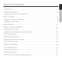
TABLE OF CONTENTS
Introduction .............................................................................................................................. 6
Operating Conditions .............................................................................................................. 6
Getting To Know Your Air Conditioner .................................................................................. 7
What’s In the Box ...................................................................................................................... 8
Installation Accessory Kit Items ............................................................................................. 8
Installation Instructions .......................................................................................................... 9
Water Drainage .......................................................................................................................10
Window Slider Kit Installation ............................................................................................. 10
Operating Instructions .......................................................................................................... 12
Control Panel and Remote Controller Displays ............................................................... 14
Functions in Detail .................................................................................................................15
Additional Unit Features ....................................................................................................... 17
Handling the Remote Controller .........................................................................................17
Basic Unit Error Codes ...........................................................................................................18
Electrical Information ............................................................................................................18
Care & Maintenance ............................................................................................................... 19
Troubleshooting Tips ............................................................................................................20
Costumer Support ..................................................................................................................21
One-Year Limited Appliance Warranty (US) ....................................................................... 22

4
ENGLISH ESPAÑOL FRANÇAIS
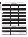
WARNING
Plug in power plug completely.
Do not start or stop the unit by inserting or
pulling out the power plug.
Do not damage power cord or replace
with a non-original power cord.
• Otherwise, it may cause electric shock or
fire due to potential short circuit.
• It may cause electric shock or fire.
• It may cause electric shock or fire.
• If the power cord is damaged, it must
be replaced by the manufacturer or an
authorized service center or a similarly
qualified person to avoid hazard.
Do not modify power cord length.
Do not operate with wet hands or in a
damp environment.
Do not direct airflow directly at room
occupants.
• It may cause electric shock or fire. • It may cause electric shock. • This could be harmful to their health.
Always ensure eective grounding/earth-
ing.
Do not allow water into or onto the front of
cabinet, control panel or power cord.
Always use dedicated power outlet and
circuit breaker.
• Incorrect or missing grounding may lead to
electric shock.
• It may cause failure of unit or electric shock. • Sharing a circuit can lead to fire.
Unplug the unit if it emits strange sounds,
smells or smoke.
Do not plug unit into an electrical socket
that is loose or damaged.
Do not operate the unit while the chas-
sis is open or removed.
• Unit may need repair. • It may cause fire and electric shock. • It may cause electric shock.
Ensure the power cord is kept away from
any heating sources.
Do not disassemble or modify unit.
Do not use the power cord near
flammable gas or combustibles, such as
gasoline, benzene, paint thinner, etc.
• It may cause fire and electric shock. • It may cause failure and electric shock. • It may cause an explosion or fire.
Ventilate room before operating
air conditioner if there was a gas leakage.
• It may cause explosion, fire, and burns.
READ THESE NOTICES CAREFULLY—THEY ARE IMPORTANT!
When the air filter is removed for cleaning,
avoid touching the internal metal parts of
the unit.
Do not clean the air conditioner with water.
Ventilate the room well when used
together with a stove, etc.
• It may cause an personal injury and/or
damage to the unit.
• Water may enter the unit and degrade the
insulation. It may cause an electric shock.
• An oxygen shortage may occur when
using a stove in a room with closed
windows.
When the unit needs to be cleaned, power
it o and unplug it.
Do not put a pet or house plant where it
will be exposed to direct air flow.
Do not use for specialized purposes.
• Do not clean unit when power is on as it
may cause fire and electric shock and/or
personal injury.
• This could injure or be harmful
to your pet or plants.
• Do not use this air conditioner to
preserve precision devices, food, pets,
plants, and art objects.
• It may cause deterioration, etc.
CAUTION

5
ENGLISHESPAÑOLFRANÇAIS
CAUTION
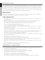
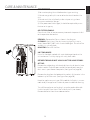
ELECTRICAL INFORMATION
• Be sure your electrical wiring is adequate for the model you have chosen. This information can be found on
the rating label, a silver-colored sticker generally located on the upper-right side of the cabinet.
• Be sure the air conditioner is properly grounded. To minimize shock and fire hazards, proper grounding is
important. The power cord is equipped with a three-prong
grounding plug for protection against shock hazards.
• Your air conditioner must be connected to a properly
grounded wall receptacle. If the wall receptacle you intend to
use is not adequately grounded or protected by a time delay
fuse or circuit breaker, have a qualified electrician install the
proper receptacle.
• Ensure the receptacle is accessible aer the unit installation. The power supply
cord contains a current device that senses damage to the power cord and excess
current draw from the unit. To test your current device do the following:
1. Plug in the Air Conditioner.
2. Press the TEST button. You will hear a click as the RESET button pops out within
the rubber housing and the LED will turn o.
3. Press the RESET button. You will hear a click as the button engages and the LED
will illuminate.
4. The power supply cord is now supplying electricity to the unit.
Note: Your model may have the TEST and RESET buttons on the side or the front
of the plug head.
NOTES:
• Do not use the TEST and RESET buttons to turn the unit on or o.
• If the current device fails the test or the power cord becomes damaged, the entire power cord must be re-
placed with an equivalent power cord and current device by a licensed electrician.
Stop operation and remove window filler
panels from window during severe storm or
hurricane.
Hold the plug by the head of the power
plug when unplugging unit.
Unplug the power cord when not using
the unit for extended periods of time.
• Operation during a severe storm may allow
a significant amount of water to enter the
indoors.
• Pulling from the wire can cause wire to fray
leading to electric shock or fire.
• Will prevent damage to the unit.
Do not place obstacles around air-intake
vents or inside cool air outlet.
Do not place heavy objects on the
power cord and ensure that the cord
is not pinched or stressed.
Always insert the filters securely.
Clean filter at least once per month.
• It may cause failure of appliance. • There is danger of fire or electric shock.
• Operation with dirty filters (or without
filters) will eect performance and may
cause damage to the unit.
Do not use strong detergent such as
wax or paint thinner to clean the unit.
Use a damp, so cloth.
• Appearance may deteriorate due to change
of product color or scratching of its surface.
CAUTION
NOTE: The power supply cord with this air conditioner
contains a current detection device designed to reduce the risk
of fire. In the event that the power supply cord is damaged, it
cannot be repaired -- it must be replaced with a cord from the
Product Manufacturer.
Side button
version

6
ENGLISH ESPAÑOL FRANÇAIS
INTRODUCTION
Thank you for purchasing this quality Impecca portable air conditioner unit. To ensure the longest life and high-
est energy eiciency of your unit, please carefully follow these operating instructions. Keep these instructions in
a safe place and consult them as needed. Please note that constant enhancement and improvements to our air
conditioning units may mean that your model will slightly dier in appearance from the model pictured in this
manual, but the actual operation and installation of the unit remains unchanged. This manual is solely provided
for informational purposes and does not constitute a binding, legal contract.
SAFETY NOTICE
This appliance should not be used by children or mentally/physically disabled persons without strict, direct su-
pervision by a responsible adult. Never play with or around the appliance.
SAFETY INFORMATION
• Before operation, ensure your electrical installation (outlets and circuits) complies with the power specifica-
tions found on the unit.
• Before cleaning or maintaining the air conditioner, please turn o air conditioner and unplug the unit.
• Make sure the power cord isn’t kinked, bent, or under the weight of sharp or heavy objects.
• Do not pull or yank the power cord to unplug the unit or move the air conditioner.
• Do not insert or unplug the power plug with wet hands.
• Only use a grounded power outlet. Make sure the grounding is functional.
• If the power cord is damaged, it must be replaced by the manufacturer or a qualified technician in order to
avoid fire and electrical hazards.
• Should abnormal operation occur (such as a burning smell), please disconnect power cord immediately
and contact your local dealer.
• If nobody is present to monitor the operation of the unit, please turn it o and disconnect the power cord.
• Do not splash or pour water on air conditioner to avoid causing a short circuit or damage to the unit.
• Do not put or hang dripping objects above the air conditioner.
• If using a drainage hose, ensure the ambient temperature remains well above freezing (32°F or 0°C) to avoid
cracking or damaging the unit.
• Keep heat sources away from the air conditioner.
• Ensure the unit is far away from fire, inflammable, or explosive objects.
• Never allow children or persons with reduced physical, sensory, or mental capabilities to operate or play
around the air conditioner without direct adult supervision.
• Never allow children to perform cleaning or other user-maintenance operations without direct adult super-
vision.
• Never attempt to repair or disassemble the air conditioner by yourself.
• Never insert objects into the air conditioner.
OPERATING CONDITIONS
• The air conditioner should only be operated within the temperature range of 62°F to 95°F (16°C to 35°C).
• The appliance is for indoor use only.
• The appliance must be positioned so that the plug is accessible.
• A perimeter of 12′′(30cm) around the air conditioner should be free of all objects.
• Do not operate the air conditioner in a humid environment.
• Please keep air inlet and air outlet clean and free of obstacles.
• During operation, close doors and windows to improve cooling eect.
• Please put the air conditioner on smooth and flat ground for operation to avoid noise and vibration.

7
ENGLISHESPAÑOLFRANÇAIS
• This air conditioner is equipped with casters that roll on smooth, flat surfaces.
• Do not tilt or turn over the air conditioner. If there’s problem, please disconnect the power supply immedi-
ately and contact your local dealer or technical support.
• Avoid exposing the unit to direct sunlight.
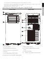
GETTING TO KNOW YOUR AIR CONDITIONER
1. Control Panel
2. Infrared Remote Receiver
3. Vertical Louver Control Lever
4. Casters
5. Carrying Handle (both sides)
6. Upper Air Filter (behind intake grille)
7. Water Drain Outlet
8. Air Outlet (exhaust hose connec-
tion)
9. Lower Air Intake
10. Bottom Tray Water Drain Outlet
B
C
D
E
F
G
H
I
J
K
FRONT VIEW REAR VIEW

8
ENGLISH ESPAÑOL FRANÇAIS
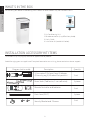
WHAT’S IN THE BOX
Please verify your box for the following items. Note that some models may not include all items.
1. Air Conditioning Unit
2. Remote controller (may dier from photo)
3. User’s Guide
4. Installation kit (see details below)
INSTALLATION ACCESSORY KIT ITEMS
Illustrations may vary slightly from actual appearance of product.
Avoid damaging your new appliance! If required accessories are missing, please contact customer support.
D
C
Diagram (not to scale)
Foam Seals (2 adhesive, 1 non-adhesive)
1) Connector 2) Exhaust hose 3) Adapter
4) Security peg 5) Window filler panel kit
Remote Controller and batteries
Drain hose (23.6”)
Security Bracket and 2 Screws
Description
Quantity
1 set
1 set
1 set
1 piece
3 pieces
ON/ OFF
TEM P
SHO RT
CUT
ON
TIM ER
TIM ER
OFF
FAN
MOD E
SLE EP
PMT S
LED
1 2 3 4
5
B

9
ENGLISHESPAÑOLFRANÇAIS
INSTALLATION INSTRUCTIONS
Carefully review all of these instructions BEFORE proceeding to install and operate your air conditioner unit. Fail-
ure to do so may cause damage, injury, or bodily harm including permanent disability and/or death.
LOCATION
• The air conditioner should be placed on a firm, level surface to minimize
noise and vibration. For safe and secure positioning, place the unit on a
smooth, level floor strong enough to support the unit.
• The unit has casters to aid in maneuverability, but it should only be
rolled on smooth, flat surfaces. Use caution when rolling on carpeted
surfaces. Do not attempt to roll the unit over objects.
• The unit must be placed within reach of a properly rated grounded socket.
• Never place any obstacles around the air inlet or outlet of the unit.
• Allow 1 to 3 feet (30cm to 100cm) of space from the wall for eicient
air-conditioning and to prevent overheating.
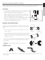
EXHAUST HOSE INSTALLATION
NOTE: For your unit to function properly, it is imperative that the exhaust
hose be vented to the outside when used in Auto, Cooling and dehumidify
modes.
1. Attach the adapters to the exhaust hose by snapping them in place as
shown in Figure B.
2. Insert the connector of the now-assembled exhaust hose into the hole
seat of the air outlet and slide the exhaust hose down along the arrow’s
direction as shown in Figure C. Pay attention to the tabs so that the con-
nector clicks into place.
The exhaust hose can be compressed or extended moderately according
to installation requirements, but it is preferable to shorten the hose to
desired length.
IMPORTANT: DO NOT OVER-BEND OR KINK THE EXHAUST HOSE.
(Figure D)
EXHAUST PORT
Make sure that there are no obstacles within 18” (50cm) around the exhaust outlet in order for the exhaust system
to work properly.
Fig. C
Fig. D
Fig. B
Fig. A
A - 12” - 39 ½” (30 CM - 100CM)
B - 12” (30 CM)
B
A
Exhaust hose
Exhaust hose
assembly
Unit Adapter Window Slider
Adapter

10
ENGLISH ESPAÑOL FRANÇAIS
WATER DRAINAGE
Certain functions of your air conditioning unit create condensation and the unit may need
to evacuate accumulated water. Please carefully follow these instructions according to your
operating and usage conditions.
COOLING MODE
During cooling mode, the unit attempts to evacuate all of the moisture through the exhaust
hose to the outside along with the warm air exhaust. At times, when the humidity level is very
high, excess water may collect in the bottom tray. If the water level of the bottom tray reaches
a predetermined level, the unit beeps 8 times, the digital display area shows error P1 . At this
time the air conditioning/dehumidification process will immediately stop, even though the fan
motor may continue running (this is normal).
Carefully move the unit to a drain location, remove the bottom drain plug and let the water
drain away (see Figure E). Reinstall the bottom drain plug and restart the machine until the P1
symbol disappears. If the error repeats, call for service.
NOTE: Be sure to reinstall the bottom drain plug before using the unit.
DEHUMIDIFYING MODE ONLY
Remove the upper drain plug from the back of the
unit and simply attach the drain hose to the hole.
Place the open end of the hose adapter directly over
the drain area in your floor or into another receptacle
(see Figure F).
NOTE: Make sure the hose is secure so there are no
leaks. Direct the hose toward a drain that is located
lower than the unit, making sure that there are no kinks that will stop water flow. Place the end of the hose into
the drain and make sure the end of the hose is down to let the water flow smoothly (see Figure F). Do not li up
the hose as this may cause water to flow back into the unit.
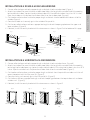
WINDOW SLIDER KIT INSTALLATION
Your window slider kit has been designed to fit most standard double-hung and slider windows, However, it may
be necessary for you to improvise/modify some aspects of the installation procedures for certain types of win-
dows. Please refer to Figure G & Figure H for minimum and maximum window openings. The window slider kit
can be fixed with an included security peg (see Figure I).
Window filler panel
Minimum: 2’ 1/8” (67.5cm)
Maximum: 4’ (123cm)
Fig. G
Standard
Double-hung
Window
Horizontal
Slider
Window
Fig. H
Window filler panel
Minimum: 2’ 2⅝” (67.5cm)
Maximum: 4’ (123cm)
Remove
drain plug
Continuous drain hose
Fig. I
Window
filler panel
Security Peg
Bottom drain
plug
Fig. E
Fig. F

11
ENGLISHESPAÑOLFRANÇAIS
INSTALLATION IN A DOUBLE-HUNG SASH WINDOW:
1. Cut one adhesive foam seal to the proper length and attach it to the window stool. (Figure J)
2. Attach the window filler panel kit to the window stool. Adjust the length of the window slider kit according
to the width of window, shorten the adjustable window kit if the width of window is less than 26 ½ inches.
Open the window sash and place the window slider kit on the window stool. (Figure K)
3. Cut the other adhesive foam seal to the proper length and attach it to the bottom of the lower rail of the
window.(Figure L)
4. Close the window sash securely against the window filler panel kit.
5. Cut the non-adhesive foam seal to an appropriate length and seal the open gap between the upper and
lower windows. (Figure M)
6. If desired, install the security bracket with the two screws as shown in Figure R at the bottom of this page.
INSTALLATION IN A HORIZONTAL SLIDER WINDOW:
1. Cut one adhesive foam seal to the proper length and attach it to the window frame. (Figure N)
2. Attach the window filler panel kit to the window stool. Adjust the length of the window slider kit according
to the height of window opening, shorten the adjustable window kit if the height of window is less than 26 ½
inches. Open the window sash and place the window slider kit on the window stool. (Figure O)
3. Cut the other adhesive foam seal to the proper length and attach it on the part of the window sash that will
come into contact with the filler panel kit. (Figure O)
4. Close the sliding sash securely against the filler panel kit. (Figure P)
5. Cut the foam seal to an appropriate length and seal the open gap between the top window sash and outer
window sash. (Figure Q)
6. If desired, install the security bracket with the two screws as shown in Figure R.
2
6
½
”
-
4
8
”
Fig. J
Fig. K
Fig. L
Fig. M
Adhesive Seal
Window stool
Window Filler
Panel Kit
Window Filler
Panel Kit
Window stool
Non-Adhesive Sash
Seal
Adhesive
Sash Seal
Lower rail
Fig. E
2 Screws
Security Bracket
Fig. N
Fig. O Fig. P Fig. Q
Fig. R
Non-Adhesive Sash
Seal
Adhesive Seal
26 ½” - 48”
Window Kit
Adhesive
Sash Seal
Window Kit

12
ENGLISH ESPAÑOL FRANÇAIS
OPERATING INSTRUCTIONS
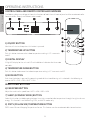
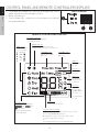
CONTROL PANEL AND REMOTE CONTROLLER OVERVIEW
The following diagram and legend shows the functions of both the unit’s control panel and the remote controller.
Some functions are only available on select models.
1) ON/OFF BUTTON
Machine will start and stop when this button is pressed.
2) TEMPERATURE UP BUTTON
Push this button to increase the indoor temperature setting in 2°F increments
to 88°F.
3) DIGITAL DISPLAY
2-Digit LED display for the unit and LCD with additional indicators for the remote
controller.
4) TEMPERATURE DOWN BUTTON
Push this button to decrease the indoor temperature setting in 2°F increments to 62°F.
5) MODE BUTTON
Each time the button is pressed, the operating mode of the air conditioning unit is selected in the following se-
quence: AUTO > COOL > DRY > HEAT* > FAN
REMOTE ONLY BUTTONS
6) FAN SPEED BUTTON
Adjust the machine fan speed from: AUTO > LOW > MED > HIGH
7) SLEEP (ECONOMY MODE) BUTTON
Select this function just before going to sleep. It maintains a comfortable temperature through the night and save
energy. This function is available during COOL, and AUTO modes only.
8) PMTS (FOLLOW ME) TEMPERATURE BUTTON
PMTS means Personal Mapping Temperature Sensor. This feature uses the remote controller to monitor tem-
F E D C B
ON/OFF
TEMP
SHORT
CUT
ON
TIMER
TIMER
OFF
FAN
MODE
SLEEP
LEDPMTS
D
B
F
G
H
I
J
K
E
L
M
C

13
ENGLISHESPAÑOLFRANÇAIS
perature in another location of the room and sends information to the unit every 3 minutes.
9) LED DISPLAY BUTTON**
Turns the temperature display on the unit on and o.
10) TIMER OFF BUTTON
Press this button to activate Auto-O. This feature turns o the unit at a programmed time within the next 24
hours.
Each press of the Timer-O button will increase the time setting in 30-minute increments, up to 10 hours, then
in 1 hour increments from 10 to 24 hours. To cancel the Auto-O time setting, just press the button until the time
setting is 0.
11) TIMER ON BUTTON
Press this button to activate Auto-On. This feature turns on the unit at a programmed time within the next 24
hours.
Each press of the Timer-On button will increase the time setting in 30-minute increments, up to 10 hours, then
in 1 hour increments from 10 to 24 hours. To cancel the Auto-On time setting, just press the button until the time
setting is 0.
12) SHORTCUT BUTTON
This button is one-touch preset for your favorite settings.
*Since your unit does not have the heat feature, you should bypass it on the remote controller.
**NOT AVAILABLE ON ALL UNITS

14
ENGLISH ESPAÑOL FRANÇAIS
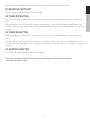
CONTROL PANEL AND REMOTE CONTROLLER DISPLAYS
1. Current operating mode COOL, FAN, DRY. When operating in AUTO
mode, none of the three indicators will be lit.
2. Power indicator light.
3. Timer indicator light - showing that a timer program was set from
the remote controller.
MODE display
Shows the current
mode, including:
Transmission Indicator
Lights up when remote attempts
to send signal to unit
AUTO
COOL
DRY
HEAT
FAN
ON/OFF indicator
Shown when the unit is turned on;
disappears when the unit is powered o
TIMER ON display
Shown when TIMER
ON is set
TIMER OFF display
Shown when TIMER
OFF is set
FAN SPEED display
Displays selected FAN SPEED:
High, Med,
Low, or Auto
This display is blank when
unit is in DRY mode
Temperature/Timer display
Displays the set temperature by default, or timer setting
when using TIMER ON/OFF functions
Temperature range: 62ºF to 82ºF (17ºC to 30ºC)
Timer setting range: 0-24 hours
This display is blank when operating in FAN mode.
SILENT icon
Not available for this unit
ECO icon
Not available for
this unit
Battery icon
Low battery
detection
SLEEP icon
Shown when
SLEEP function
is activated
PMTS icon
display
Indicates that
the FOLLOW ME
function is on
Not available for
this unit
REMOTE CONTROLLER DISPLAY
B
C D
UNIT DISPLAY

15
ENGLISHESPAÑOLFRANÇAIS
FUNCTIONS IN DETAIL
Instructions are for both the remote controller and the
unit control panel itself. When using the remote con-
troller, it is possible and even recommended to select
the operating mode before you press ON/OFF to start
the unit. On the unit’s control panel this is not possible
and you must begin with the unit on.
AUTO MODE OPERATION:
Ensure the unit is plugged in and power is available.
The indicator on the display panel of the indoor unit
will illuminate.
1. Press the MODE button to select AUTO.
2. Press the TEMP UP or TEMP DOWN buttons to set
the desired temperature. The temperature can be
set within a range of 62° to 88°F in 2° increments.
NOTES:
• In AUTO mode, the air conditioner will switch be-
tween cooling, fan, and dehumidifying modes by
sensing the dierence between the actual ambient
room temperature and the set temperature on the
remote controller.
• In AUTO mode, you cannot switch the fan speed. It
is automatically controlled for maximum eiciency.
COOL MODE OPERATION:
Ensure the unit is plugged in and power is available.
1. Press the MODE button to select COOL mode.
2. Press the TEMP UP or TEMP DOWN buttons to set
the desired temperature. The temperature can be
set within a range of 62° to 88°F in 2° increments.
3. Press the FAN SPEED button to choose an appro-
priate fan speed: LOW, MED, HIGH, or AUTO.
Note:
• When in AUTO fan mode the remote controller LCD
will not show any indicator for the fan speed.
FAN MODE OPERATION:
1. Press the MODE button to select FAN mode.
2. Press the FAN SPEED button to choose an appro-
priate fan speed: LOW, MED, HIGH, or AUTO.
Notes:
• FAN mode simply circulates air and does not influ-
ence the room’s ambient temperature. You cannot
adjust the temperature in FAN mode.
• There is no need to connect the exhaust hose to a
window in fan mode.
DEHUMIDIFIER MODE OPERATION:
Ensure the unit is plugged in and power is available.
1. Press the MODE button to select DRY mode.
2. Press the TEMP UP or TEMP DOWN buttons to set
the desired temperature. The temperature can be
set within a range of 62° to 88°F in 2° increments.
NOTE: DRY mode controls fan speed automatically for
eective dehumidification. This cannot be adjusted
DELAY START/STOP (TIMER) INSTRUCTIONS:
The timer buttons enable two separate functions:
one to automatically start the unit within a 24 hour
period of time and another to automatically turn
o the unit within a 24 hour period of time. These
functions are called, respectively, AUTO ON and
AUTO OFF.
Note that the instructions below make reference to
the TIMER ON and TIMER OFF buttons which are
found on the remote controller.
AUTO ON INSTRUCTIONS:
1. Press the TIMER ON button. The remote controller
shows TIMER ON, the last Auto-on setting time and
the indicator “h” (indicating “hours”) will be shown
on the remote controller LCD. Now you are ready to
reset the Auto-on time to START the operation.
2. Push the TIMER ON button again to set desired
Auto On time. Each time you press the TIMER ON
button, the time will increase in 30 minutes incre-
ments, up to 10 hours, then in 1 hour increments
up to 24 hours.
3. Aer setting the TIMER ON, there will be a one-half
second delay before the remote controller trans-
mits the signal to the air conditioner. Then, aer
approximately another 2 seconds, the signal “h”
will disappear and the set temperature will re-ap-
pear on the LCD display window.
AUTO OFF INSTRUCTIONS:
1. Press the TIMER OFF button. The remote control-
ler shows TIMER OFF, the last Auto-o setting time
and the signal “h” will be shown on the LCD display
area. Now it is ready to reset the Auto-o time to
START the operation.

16
ENGLISH ESPAÑOL FRANÇAIS
2. Push the TIMER OFF button again to set desired
Auto-o time. Each time you press the button, the
time increases in 30 minutes increments, up to 10
hours, then at 1 hour increments up to 24 hours.
3. Aer setting the TIMER OFF, there will be a one-
half second delay before the remote controller
transmits the signal to the air conditioner. Then,
aer approximately another 2 seconds, the signal
“h” will disappear and the set temperature will
re-appear on the LCD window.
EXAMPLES OF TIMERS:
AUTO ON: If you’d like your home or oice to be
cool aer returning from an event or running er-
rands, schedule the machine to turn on and cool the
room for your arrival.
To set the machine to start in 6 hours, push the
TIMER ON button. The display will read “h”; push
the TIMER ON button until the display reads “6.0”.
Wait 3 seconds and the program will be activated
once the LED resumes displaying the room tempera-
ture.
AUTO OFF: Your children rarely turn the air condi-
tioning o during the day and you leave for work
before they leave for school. Consider scheduling
the unit to turn o automatically.
To set the machine to turn o in 1 hour, push the
TIMER OFF button. The display will read “h”; push
the TIMER OFF button until the display reads “1.0”.
Wait 3 seconds and the program will be activated
once the LED resumes displaying the room tempera-
ture.
COMBINED TIMERS: You can use the Auto On and
Auto O functions simultaneously. An example of
this feature is to turn o the unit in 1 hour when the
kids leave for school and turn it on in 6 hours just
before you return from work.
(See above.)
SLEEP (Economy) operation
• Press this button, the selected temperature will in-
crease by 2°F /1°C aer 30 minutes. The tempera-
ture will then increase by another 2°F /1°C aer an
additional 30 minutes.
• The new temperature will be maintained for seven
hours before it returns to the originally selected
temperature, at which point Sleep mode ends
and the unit will continue to operate as originally
programmed.
• NOTE: This feature is unavailable under FAN or
DRY modes.
PMTS (FOLLOW ME) Feature:
• NOTE: This feature can be activated from the
remote controller ONLY. The remote controller acts
as a remote thermostat allowing for the precise
temperature control at its location.
• To activate the Follow Me/Temp Sensing feature,
point the remote controller towards the unit and
press the PMTS/Follow Me button. The remote
displays the actual temperature at its location.
The remote controller will send this signal to the
air conditioner every three minutes interval until
press the Follow Me/Temp Sensing button again.
• If the unit does not receive the PMTS signal during
any seven-minute interval, the unit will beep to
indicate the PMTS mode has ended.
SHORTCUT Feature:
• This button is one-touch preset for your favorite
settings.
• The same button is used to store the current set-
tings or recall previous settings.
• The first time the button is pressed, the unit will
operate on AUTO mode, 78ºF and AUTO fan speed
• Pushing it a second time should revert to all
previous settings including operating mode,
temperature, fan speed level and sleep feature (if
activated)
• To store the current mode, temperature, fan speed
level, etc. into memory, hold the button for at least
2 seconds.

17
ENGLISHESPAÑOLFRANÇAIS
ADDITIONAL UNIT FEATURES
Auto Restart
• If the unit shuts o unexpectedly due to a power outage, it will restart with the previous function setting
automatically when the power resumes.
• If you need full timer functionally you can hook up a properly-rated heavy duty timer to the unit to control on
and o cycles. If doing so, it is imperative to avoid circumventing the third prong ground wire and having a
timer that is rated accordingly to prevent risk of fire or electric shock.
Self Protection
• Aer the unit has stopped, it cannot resume operation for 3 minutes following shut down. This is to protect
the unit. Operation will automatically resume aer 3 minutes has elapsed.
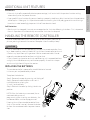
HANDLING THE REMOTE CONTROLLER
Use the remote controller within a distance of 26 feet (8 meters) from the ap-
pliance, pointing it towards the receiver. Reception is confirmed by a beep.
CAUTION
• The air conditioner will not received signals from the remote controller if cur-
tains, doors or other materials block the signals from the controller to the unit.
• Prevent any liquid from spilling onto or into the remote controller. Do not
expose the remote controller to direct sunlight or heat.
• If the infrared signal receiver on the air conditioning unit is exposed to direct
sunlight, the air conditioner may not function properly. Use curtains to pre-
vent the sunlight from falling on the receiver.
REPLACING THE BATTERIES
The remote controller is powered by two AAA batteries housed
in the rear part and protected by a cover.
To replace the batteries:
Step 1: Remove the cover by pressing and sliding o.
Step 2: Remove the old batteries and insert 2
new AAA batteries, placing the
(+) and (-) ends correctly.
Step 3: Reattach the cover by sliding it back into
position.
NOTE: When the batteries are removed, the re-
mote controller erases all
programming. Aer inserting new batteries, the
remote controller must be reprogrammed.
If storing the unit for extended periods of time
(such as the end of a season) remove the batter-
ies from the remote controller to prevent corro-
sion.
ON/OF F
TEMP
SHORT
CUT
ON
TIMER
TIMER
OFF
FAN
MODE
SLEEP
FOLLOW
SWING
ION
LED
ME
26 ft.

18
ENGLISH ESPAÑOL FRANÇAIS
CAUTION
ADDITIONAL REMOTE CONTROLLER INFORMATION
• Do not mix old and new batteries or batteries of a dierent type (e.g. alkaline and zinc).
• Do not leave the batteries in the remote controller if it is not going to be used for 2–3 months.
• Dispose of the old batteries in special battery disposal collection containers at sales sites or wherever local law
states batteries may be disposed of.
REMOTE CONTROLLER SPECIFICATIONS
Rated Voltage 3.0V (Dry batteries AAA x2)
Signal Receiving Range 26 feet / 8m
Environment ~23° F to 140° F (-5°C to 60°C)
BASIC UNIT ERROR CODES
Use the following guidelines to understand and troubleshoot common error codes.
E1: Room temperature sensor error.
E2: Evaporator temperature sensor error
E3: Condenser temperature sensor error
E4: Display panel communication error
• For all of the above errors, unplug the unit and plug it back in.
P1: Bottom condensation tray is full
• Connect the drain hose and drain the collected water away.
• Note that frequent draining may be required, especially in humid climates
and during seasonal weather changes.
• If protection repeats aer draining, call for service.
ELECTRICAL INFORMATION
• 115 Volts, 60Hz, 1Ph
• 10-12 Amps (depending on model)
• Power cord length: 8.69’
• EER: 8.9
• Plug Face: 5-15P
5-15P

19
ENGLISHESPAÑOLFRANÇAIS
CARE & MAINTENANCE
IMPORTANT
1) Be sure to unplug the unit before cleaning or servicing.
2) Do not use gasoline, thinner or other chemicals to clean the
unit.
3) Do not wash the unit directly under a tap or using a hose.
It may cause electrical danger.
4) If the power cord is damaged, it should be repaired by manu-
facturer or its agency.
AIR FILTER CLEANING:
Clean the air filter at least once every two weeks to prevent inferi-
or fan operation due to dust.
REMOVAL: Remove the filter as shown in the diagram.
CLEANING: Wash the air filter by immersing it gently in warm
water (about 104°F/ 40°C) with a neutral detergent. Rinse the filter
and dry it in a shady place.
MOUNTING: Reinstall the filter.
UNIT ENCLOSURE:
Use a lint-free cloth soaked with neutral detergent to clean the
unit enclosure. Finish by wiping with a dry clean cloth.
BEFORE STORING OR NOT USING A UNIT FOR LONG PERIODS
OF TIME:
Remove the rubber plug at the back of the unit and attach a hose
to drain outlet. Place the open end of the hose directly over the
drain area in your floor or receptacle. (See figure F on page 10.)
Remove the plug from the bottom drain outlet, all the water in the
bottom tray will drain out. (See Figure E on page 10.)
Keep the appliance running on FAN mode for half a day in a warm
room to dry the appliance inside and prevent mold from forming.
Turn o the appliance and unplug it, wrap the cord and bundle
it with the tape. Clean the air filter and reinstall it (see above).
Remove batteries from the remote controller.

20
ENGLISH ESPAÑOL FRANÇAIS
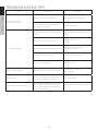
TROUBLESHOOTING TIPS
Problem Possible Causes Remedies
Unit does not start when
pressing on/o button
P1 appears in the display window
Drain the water in the bottom tray
Room temperature is lower than the set
temperature (cool mode)
Reset the temperature
Room not cool enough
The windows or doors in the room are not
closed
Make sure all the windows and doors are
closed
There are heat sources inside the room
Remove the heat sources
if possible
Exhaust air duct is not connected or blocked
Connect the duct and make sure
it can function properly
Temperature setting is too high Decrease the set temperature
Air filter is blocked by dust Clean the air filter
Machine noisy or vibrates The ground is not level or not flat enough
Place the unit on a flat, level
surface if possible
Gurgling noises
The sound comes from the flowing of the
refrigerant inside the air conditioner unit
This noise is normal
Power shuts o in heating mode
The automatic overheat protection function
kicks in. When the temperature at the air
outlet exceeds 158°F/70°C, the device will
automatically shut o.
Switch on again aer the unit has cooled
o.
La page est en cours de chargement...
La page est en cours de chargement...
La page est en cours de chargement...
La page est en cours de chargement...
-
 1
1
-
 2
2
-
 3
3
-
 4
4
-
 5
5
-
 6
6
-
 7
7
-
 8
8
-
 9
9
-
 10
10
-
 11
11
-
 12
12
-
 13
13
-
 14
14
-
 15
15
-
 16
16
-
 17
17
-
 18
18
-
 19
19
-
 20
20
-
 21
21
-
 22
22
-
 23
23
-
 24
24


Impecca IPAC06DR Manuel utilisateur
- Catégorie
- Climatiseurs mobiles
- Taper
- Manuel utilisateur
dans d''autres langues
- English: Impecca IPAC06DR User manual
Documents connexes
-
Impecca IPAC10-LR Mode d'emploi
-
-
-
-
-
-
-
-
-
Autres documents
-
Electrolux EXP09CKEWI Manuel utilisateur
-
Electrolux EXP11CKEWI Manuel utilisateur
-
AEG AXP09HSECI Manuel utilisateur
-
Danby DPA085B1GB Le manuel du propriétaire
-
-
AEG AXP26V578HW Manuel utilisateur
-
Honeywell HL12CESWW Manuel utilisateur
-
 Quilo QP112WK Mode d'emploi
-
-
