Yamaha 01V96 Le manuel du propriétaire
- Catégorie
- Mélangeurs audio
- Taper
- Le manuel du propriétaire
Ce manuel convient également à

EN
Owner’s Manual
Keep This Manual For Future Reference.

2 Contents
01V96i—Owner’s Manual
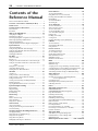
Contents
PRECAUTIONS ...................................5
Welcome .......................................... 7
Package Contents ......................................... 7
About the utility software ........................... 7
Firmware updates ........................................ 8
About this Owner’s Manual ....................... 8
Conventions Used in this Manual ............. 8
Control Surface & Rear Panel .......... 9
Control Surface ............................................ 9
Rear Panel ................................................... 16
Installing an Optional Card ..................... 18
Operating Basics ............................ 19
About the Display ...................................... 19
Selecting Display Pages ............................. 20
Display Interface ........................................ 20
Selecting Layers .......................................... 21
Selecting Channels ..................................... 22
Selecting Fader Modes .............................. 22
Metering ...................................................... 23
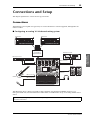
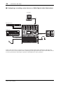
Connections and Setup ................. 25
Connections ................................................ 25
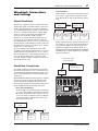
Wordclock Connections and Settings .... 27
Input and Output Patching ...................... 29
Tutorial .......................................... 31
Input and Output Patching ...................... 31
Setting the Input Levels ............................ 32
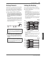
Pairing Channels ........................................ 33
Setting the Routing .................................... 33
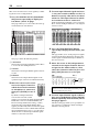
EQ’ing the Input Signals ........................... 35
Using the EQ Library ................................ 36
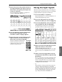
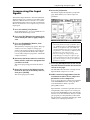
Compressing the Input Signals ................ 37
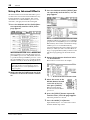
Using the Internal Effects ......................... 38
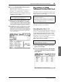
Recording to DAW Software via
the USB Port ........................................... 39
Adjusting the Monitor Levels from
the DAW .................................................. 41
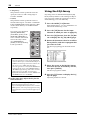
Using Scene Memories .............................. 42
Changing the Channel Names ................. 43
Creating a Custom Layer by Combining
Channels (User Assignable Layer) ....... 44
Using the Oscillator .................................. 45
Using the User Defined Keys ................... 46
Using Operation Lock ............................... 47
Initializing .................................................. 48
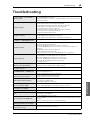
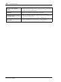
Troubleshooting ............................ 49
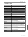
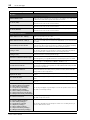
Error messages .............................. 51
Contents of the Reference
Manual ........................................... 54
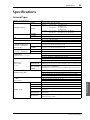
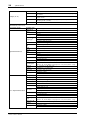
Specifications ................................. 55
General Spec ............................................... 55
Libraries ...................................................... 60
Analog Input Spec ..................................... 61
Analog Output Specs ................................ 61
Digital Input Spec ...................................... 62
Digital Output Spec ................................... 62
I/O SLOT Spec ........................................... 63
MIDI/USB/WORD CLOCK I/O Spec .... 64
Dimensions ................................................ 64
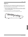
Options .......................................... 65
Rack Mounting the 01V96i Using RK1
Rack Mount Kit ...................................... 65
Index .............................................. 66
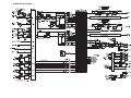
01V96i Block Diagram.......End of Manual
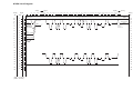
01V96i Level Diagram.......End of Manual

The above warning is located on the rear
of the unit.
• Explanation of Graphical Symbols
The lightning flash with arrowhead symbol
within an equilateral triangle is intended to
alert the user to the presence of uninsulated
“dangerous voltage” within the product’s
enclosure that may be of sufficient magnitude
to constitute a risk of electric shock to persons.
The exclamation point within an equilateral
triangle is intended to alert the user to the
presence of important operating and mainte-
nance (servicing) instructions in the literature
accompanying the product.
IMPORTANT SAFETY INSTRUCTIONS
1 Read these instructions.
2 Keep these instructions.
3 Heed all warnings.
4 Follow all instructions.
5 Do not use this apparatus near water.
6 Clean only with dry cloth.
7 Do not block any ventilation openings. Install in
accordance with the manufacturer’s instruc-
tions.
8 Do not install near any heat sources such as
radiators, heat registers, stoves, or other appa-
ratus (including amplifiers) that produce heat.
9 Do not defeat the safety purpose of the polar-
ized or grounding-type plug. A polarized plug
has two blades with one wider than the other. A
grounding type plug has two blades and a third
grounding prong. The wide blade or the third
prong are provided for your safety. If the pro-
vided plug does not fit into your outlet, consult
an electrician for replacement of the obsolete
outlet.
10 Protect the power cord from being walked on or
pinched particularly at plugs, convenience
receptacles, and the point where they exit from
the apparatus.
11 Only use attachments/accessories specified by
the manufacturer.
12 Use only with the cart, stand,
tripod, bracket, or table spec-
ified by the manufacturer, or
sold with the apparatus.
When a cart is used, use cau-
tion when moving the cart/
apparatus combination to
avoid injury from tip-over.
13 Unplug this apparatus during lightning storms
or when unused for long periods of time.
14 Refer all servicing to qualified service person-
nel. Servicing is required when the apparatus
has been damaged in any way, such as power-
supply cord or plug is damaged, liquid has been
spilled or objects have fallen into the apparatus,
the apparatus has been exposed to rain or mois-
ture, does not operate normally, or has been
dropped.
CAUTION: TO REDUCE THE RISK OF
ELECTRIC SHOCK, DO NOT REMOVE
COVER (OR BACK). NO USER-SERVICEABLE
PARTS INSIDE. REFER SERVICING TO
QUALIFIED SERVICE PERSONNEL.
CAUTION
RISK OF ELECTRIC SHOCK
DO NOT OPEN
WARNING
TO REDUCE THE RISK OF FIRE OR ELECTRIC SHOCK,
DO NOT EXPOSE THIS APPARATUS TO RAIN OR MOISTURE.

1. IMPORTANT NOTICE: DO NOT MODIFY THIS UNIT!
This product, when installed as indicated in the instructions con-
tained in this manual, meets FCC requirements. Modifications not
expressly approved by Yamaha may void your authority, granted by
the FCC, to use the product.
2. IMPORTANT: When connecting this product to accessories and/
or another product use only high quality shielded cables. Cable/s
supplied with this product MUST be used. Follow all installation
instructions. Failure to follow instructions could void your FCC
authorization to use this product in the USA.
3. NOTE: This product has been tested and found to comply with the
requirements listed in FCC Regulations, Part 15 for Class “B” digital
devices. Compliance with these requirements provides a reason-
able level of assurance that your use of this product in a residential
environment will not result in harmful interference with other elec-
tronic devices. This equipment generates/uses radio frequencies
and, if not installed and used according to the instructions found in
the users manual, may cause interference harmful to the operation
of other electronic devices. Compliance with FCC regulations does
* This applies only to products distributed by YAMAHA CORPORATION OF AMERICA. (class B)
not guarantee that interference will not occur in all installations. If
this product is found to be the source of interference, which can be
determined by turning the unit “OFF” and “ON”, please try to elimi-
nate the problem by using one of the following measures:
Relocate either this product or the device that is being affected by
the interference.
Utilize power outlets that are on different branch (circuit breaker or
fuse) circuits or install AC line filter/s.
In the case of radio or TV interference, relocate/reorient the
antenna. If the antenna lead-in is 300 ohm ribbon lead, change the
lead-in to co-axial type cable.
If these corrective measures do not produce satisfactory results,
please contact the local retailer authorized to distribute this type of
product. If you can not locate the appropriate retailer, please con-
tact Yamaha Corporation of America, Electronic Service Division,
6600 Orangethorpe Ave, Buena Park, CA90620
The above statements apply ONLY to those products distributed by
Yamaha Corporation of America or its subsidiaries.
FCC INFORMATION (U.S.A.)
IMPORTANT NOTICE FOR THE UNITED KINGDOM
Connecting the Plug and Cord
WARNING: THIS APPARATUS MUST BE EARTHED
IMPORTANT. The wires in this mains lead are coloured in accordance
with the following code:
GREEN-AND-YELLOW : EARTH
BLUE : NEUTRAL
BROWN : LIVE
As the colours of the wires in the mains lead of this apparatus may not
correspond with the coloured markings identifying the terminals in
your plug proceed as follows:
The wire which is coloured GREEN-and-YELLOW must be connected
to the terminal in the plug which is marked by the letter E or by the
safety earth symbol or colored GREEN or GREEN-and-YELLOW.
The wire which is coloured BLUE must be connected to the terminal
which is marked with the letter N or coloured BLACK.
The wire which is coloured BROWN must be connected to the termi-
nal which is marked with the letter L or coloured RED.
(3 wires)
ADVARSEL!
Lithiumbatteri—Eksplosionsfare ved fejlagtig håndtering. Udskiftning
må kun ske med batteri af samme fabrikat og type. Levér det brugte
batteri tilbage til leverandoren.
VARNING
Explosionsfara vid felaktigt batteribyte. Använd samma batterityp eller
en ekvivalent typ som rekommenderas av apparattillverkaren.
Kassera använt batteri enligt fabrikantens instruktion.
VAROITUS
Paristo voi räjähtää, jos se on virheellisesti asennettu. Vaihda paristo
ainoastaan laitevalmistajan suosittelemaan tyyppiin. Hävitä käytetty
paristo valmistajan ohjeiden mukaisesti.
(lithium caution)
NEDERLAND / THE NETHERLANDS
• Dit apparaat bevat een lithium batterij voor geheugen back-up.
• This apparatus contains a lithium battery for memory back-up.
• Raadpleeg uw leverancier over de verwijdering van de batterij op het
moment dat u het apparaat ann het einde van de levensduur of
gelieve dan contact op te nemen met de vertegenwoordiging van
Yamaha in uw land.
• For the removal of the battery at the moment of the disposal at the
end of life please consult your retailer or Yamaha representative
office in your country.
• Gooi de batterij niet weg, maar lever hem in als KCA.
• Do not throw away the battery. Instead, hand it in as small chemical
waste.
(lithium disposal)
This product contains a battery that contains perchlorate material.
Perchlorate Material—special handling may apply,
See www.dtsc.ca.gov/hazardouswaste/perchlorate.
* This applies only to products distributed by
YAMAHA CORPORATION OF AMERICA.
(Perchlorate)
* This applies only to products distributed by
YAMAHA CORPORATION OF AMERICA.
COMPLIANCE INFORMATION STATEMENT
(DECLARATION OF CONFORMITY PROCEDURE)
Responsible Party : Yamaha Corporation of America
Address : 6600 Orangethorpe Ave., Buena Park, Calif.
90620
Telephone : 714-522-9011
Type of Equipment : Digital Mixing Console
Model Name : 01V96i
This device complies with Part 15 of the FCC Rules.
Operation is subject to the following two conditions:
1) this device may not cause harmful interference, and
2) this device must accept any interference received including interfer-
ence that may cause undesired operation.
See user manual instructions if interference to radio reception is sus-
pected.
(FCC DoC)
This product contains a high intensity lamp that contains
a small amount of mercury. Disposal of this material
may be regulated due to environmental considerations.
For disposal information in the United States, refer to
the Electronic Industries Alliance web site:
www.eiae.org
(mercury)* This applies only to products distributed by
YAMAHA CORPORATION OF AMERICA.

PRECAUTIONS
PLEASE READ CAREFULLY BEFORE PROCEEDING
* Please keep this manual in a safe place for future reference.
WARNING
Always follow the basic precautions listed below to avoid the possibility of serious injury or even death from electrical
shock, short-circuiting, damages, fire or other hazards. These precautions include, but are not limited to, the following:
• Do not place the power cord near heat sources such as heaters or radiators, and
do not excessively bend or otherwise damage the cord, place heavy objects on
it, or place it in a position where anyone could walk on, trip over, or roll anything
over it.
• Only use the voltage specified as correct for the device. The required voltage is
printed on the name plate of the device.
• Use only the supplied power cord/plug.
If you intend to use the device in an area other than in the one you purchased,
the included power cord may not be compatible. Please check with your Yamaha
dealer.
• Check the electric plug periodically and remove any dirt or dust which may have
accumulated on it.
• Be sure to connect to an appropriate outlet with a protective grounding
connection. Improper grounding can result in electrical shock.
• This device contains no user-serviceable parts. Do not open the device or
attempt to disassemble the internal parts or modify them in any way. If it should
appear to be malfunctioning, discontinue use immediately and have it inspected
by qualified Yamaha service personnel.
• Do not expose the device to rain, use it near water or in damp or wet conditions,
or place on it any containers (such as vases, bottles or glasses) containing
liquids which might spill into any openings. If any liquid such as water seeps
into the device, turn off the power immediately and unplug the power cord from
the AC outlet. Then have the device inspected by qualified Yamaha service
personnel.
• Never insert or remove an electric plug with wet hands.
• Do not put burning items, such as candles, on the unit. A burning item may fall
over and cause a fire.
• When one of the following problems occur, immediately turn off the power
switch and disconnect the electric plug from the outlet. Then have the device
inspected by Yamaha service personnel.
- The power cord or plug becomes frayed or damaged.
- It emits unusual smells or smoke.
- Some object has been dropped into the device.
- There is a sudden loss of sound during use of the device.
• If this device should be dropped or damaged, immediately turn off the power
switch, disconnect the electric plug from the outlet, and have the device
inspected by qualified Yamaha service personnel.
CAUTION
Always follow the basic precautions listed below to avoid the possibility of physical injury to you or others, or damage
to the device or other property. These precautions include, but are not limited to, the following:
• When removing the electric plug from the device or an outlet, always hold the
plug itself and not the cord. Pulling by the cord can damage it.
• Remove the electric plug from the outlet when the device is not to be used for
extended periods of time, or during electrical storms.
• Do not place the device in an unstable position where it might accidentally fall
over.
• Do not block the vents. This device has ventilation holes at the rear and sides to
prevent the internal temperature from becoming too high. In particular, do not
place the device on its side or upside down. Inadequate ventilation can result in
overheating, possibly causing damage to the device(s), or even fire.
• If mounting this device in an EIA-standard rack, leave the back of the rack open,
and keep the rack least 10 cm from the wall. If you mount this device in a rack
together with a device that tends to generate heat, such as a power amp, take
precautions to prevent heat from building up inside this device, for example by
leaving space between the devices and by installing ventilation panels.
• Do not hold the bottom of the device when transporting or moving it. In doing
so, you may pinch your hands under the device, and result in injury.
• Do not press the rear panel of the device against the wall. Doing so may cause
the plug to come in contact with the wall and detach from the power cord,
resulting in short circuiting, malfunction, or even fire.
• Do not place the device in a location where it may come into contact with
corrosive gases or salt air. Doing so may result in malfunction.
• Before moving the device, remove all connected cables.
• When setting up the device, make sure that the AC outlet you are using is easily
accessible. If some trouble or malfunction occurs, immediately turn off the
power switch and disconnect the plug from the outlet. Even when the power
switch is turned off, electricity is still flowing to the product at the minimum
level. When you are not using the product for a long time, make sure to unplug
the power cord from the wall AC outlet.
Power supply/Power cord
Do not open
Water warning
Fire warning
If you notice any abnormality
Power supply/Power cord
Location
PA_en_1 1/2

• Before connecting the device to other devices, turn off the power for all devices.
Before turning the power on or off for all devices, set all volume levels to
minimum.
• Remove the power plug from the AC outlet when cleaning the device.
• Do not insert your fingers or hands in any gaps or openings on the device
(vents, etc.).
• Avoid inserting or dropping foreign objects (paper, plastic, metal, etc.) into any
gaps or openings on the device (vents, etc.) If this happens, turn off the power
immediately and unplug the power cord from the AC outlet. Then have the
device inspected by qualified Yamaha service personnel.
• Do not rest your weight on the device or place heavy objects on it, and avoid use
excessive force on the buttons, switches or connectors.
• Do not use the headphones for a long period of time at a high or uncomfortable
volume level, since this can cause permanent hearing loss. If you experience
any hearing loss or ringing in the ears, consult a physician.
Notice
Please observe the following precautions to prevent this
device from malfunction or damage, and to avoid loss of
data.
• Do not use this device near another electrical product such as a television,
radio, stereo, or portable phone. Doing so may cause noise to be heard from this
device or from the television or radio.
• Do not use this device in locations exposed to direct sunlight (such as the
interior of a vehicle during the daytime), in locations of extremely high
temperature such as near a stove, in locations of extremely low temperature, or
in locations of excessive dust or heavy vibration. Doing so may cause the panel
of this device to deform, cause malfunctions in the internal components, or
cause operation to become unstable.
•
Do not place vinyl, plastic, or rubber items on this device. Doing so
may cause the panel to be discolored or disfigured.
• This device has a built-in backup battery. When you unplug the power cord from
the AC outlet, the internal data is retained. However, if the backup battery fully
discharges, this data will be lost. If the backup battery is running low, when you
turn on the device the display indicates “WARNING Low Battery!.” In this case,
immediately save the data to an external media using MIDI Bulk Dump, then
have qualified Yamaha service personnel replace the backup battery.
The average life of the internal backup battery is approximately 5 years,
depending on operating conditions.
Information
* The illustrations and screen displays as shown in this Owner’s Manual are for
instructional purposes only, and may be different from the ones on your device.
* The company names and product names in this Owner’s Manual are the
trademarks or registered trademarks of their respective companies.
Always turn the power off when the device is not in use.
The performance of components with moving contacts, such as switches, volume
controls, and connectors, deteriorates over time. Consult qualified Yamaha service
personnel about replacing defective components.
(weee_eu)
Connections
Maintenance
Handling caution
Precautions for care and handling
Backup battery
Yamaha cannot be held responsible for damage caused by improper use or
modifications to the device, or data that is lost or destroyed.
Information for Users on Collection and Disposal of Old
Equipment
This symbol on the products, packaging, and/or
accompanying documents means that used electrical
and electronic products should not be mixed with
general household waste.
For proper treatment, recovery and recycling of old
products, please take them to applicable collection
points, in accordance with your national legislation and
the Directives 2002/96/EC.
By disposing of these products correctly, you will help to save valuable
resources and prevent any potential negative effects on human health and the
environment which could otherwise arise from inappropriate waste handling.
For more information about collection and recycling of old products, please
contact your local municipality, your waste disposal service or the point of sale
where you purchased the items.
[For business users in the European Union]
If you wish to discard electrical and electronic equipment, please contact your
dealer or supplier for further information.
[Information on Disposal in other Countries outside the European
Union]
This symbol is only valid in the European Union. If you wish to discard these
items, please contact your local authorities or dealer and ask for the correct
method of disposal.
PA_en_1 2/2

Welcome 7
01V96i—Owner’s Manual
Welcome
Welcome
Thank you for choosing the Yamaha 01V96i Digital
Mixing Console.
The compact 01V96i Digital Console features
24-bit/96 kHz digital audio processing without com-
promise, as well as 40-channel simultaneous mixing.
The 01V96i covers a broad range of needs and applica-
tions including multi-track recording, 2-channel mix-
down, and surround sound production.
Package Contents
•Power cord
•Owner’s manual (this document)
• CUBASE AI DOWNLOAD INFORMATION
(printed)
About the utility software
The provided utility software allows you to use the
01V96i connected with your computer.
■ Yamaha Steinberg USB Driver
This is driver software for connecting the 01V96i to
your computer. Installing it in your computer will allow
audio/MIDI communication to occur.
■ 01V96i Editor
This is software that allows you to make settings for the
01V96i console from your computer. It also allows you
to back up the settings of the console, and to create set-
ups even when the physical console is not available.
01V96i Editor runs within the platform software “Stu-
dio Manager Version 2.”
■ Studio Manager Version 2
This is software that centrally manages multiple editors.
01V96i Editor also runs within this software. It allows
you to save or recall settings for multiple devices simul-
taneously.
These software can be downloaded from the Yamaha
Pro Audio website.
http://www.yamahaproaudio.com/
For details on installation and setup, refer to the above
website and to the installation guide that was included
with the program you downloaded.

8 Welcome
01V96i—Owner’s Manual
Firmware updates
This product is designed to allow the internal firmware
to be updated in order to improve performance, add
functionality, or fix problems. Firmware updates are
performed with the product connected to a computer,
so you must first install the “Yamaha Steinberg USB
Driver” in your computer.
Firmware updating is performed using update soft-
ware. You can download the update software from the
following website.
http://www.yamahaproaudio.com/
For details on the update procedure and settings, refer
to the firmware update guide provided on the website.
About this Owner’s
Manual
■ Owner’s manual (this document)
The owner’s manual describes the names and functions
of items on the panels, and explains basic operation.
■ Reference manual (PDF format)
This explains details of the functionality, the effect
parameters, and MIDI-related functions.
The Reference Manual is available on the Yamaha Pro
Audio website.
http://www.yamahaproaudio.com/
Conventions Used in this
Manual
The 01V96i features two types of buttons: physical but-
tons that you can press (e.g., ENTER and DISPLAY)
and buttons that appear on the display pages. Refer-
ences to physical buttons are enclosed in square brack-
ets, for example, “press the [ENTER] button.”
References to display page buttons are not emphasized,
for example, “move the cursor to the ON button.”
You can select display pages by using the [DISPLAY]
buttons or the Left Tab Scroll, Right Tab Scroll, and
F1–4 buttons below the display. In order to simplify
explanations, the procedures reference only the [DIS-
PLAY] button method.
See “Selecting Display Pages” on page 20 for details on
all the ways in which you can select pages.
Using the PDF manual
The reference manual is provided as a PDF-format
electronic file that you can view on your computer. By
using “Adobe
®Reader®” to view this file on your com-
puter, you’ll be able to rapidly search for terms, print
only the pages you require, or click a link to access a
relevant section. In particular, searching for terms
and clicking links are conveniences available only in
an electronic file, and we hope you take advantage of
these possibilities.
The latest version of Adobe Reader can be down-
loaded from the following website.
http://www.adobe.com/

Control Surface & Rear Panel 9
01V96i—Owner’s Manual
Control Surface
& Rear Panel
Control Surface & Rear Panel
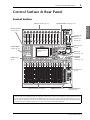
Control Surface
SOLO SOLO
ON ON
SOLO
ON
SOLO
ON
SOLO
ON
SOLO
ON
SOLO
ON
SOLO
ON
SOLO
ON
SOLO
ON
SOLO
ON
SOLO
ON
SOLO
ON
SOLO
ON
SOLO
ON
SOLO
ON
SOLO
ON
SOLO
ONON
PEAK
SIGNAL
PEAK
SIGNAL
PEAK
SIGNAL
PEAK
SIGNAL
PEAK
SIGNAL
PEAK
SIGNAL
PEAK
SIGNAL
PEAK
SIGNAL
PEAK
SIGNAL
PEAK
SIGNAL
PEAK
SIGNAL
PEAK
SIGNAL
PEAK
SIGNAL
PEAK
SIGNAL
1-16 17-32 MASTER REMOTE
LAYER
SEL SEL SEL SEL SEL SEL SEL SEL SEL SEL SEL SEL SEL SEL SEL SEL SEL SELSEL
ST IN
ENTER
STEREO
DEC INC
SOLO CLEAR
RECALL
STORE
SCENE MEMORY
PHONES
MONITOR
OUT
MONITOR
2TR IN
CH15
/
16
2TR IN
LEVEL
PHONES
LEVEL
0
10
0
10
+4
-26
GAIN
+4
-26
GAIN
+4
-26
GAIN
GAIN
+4
-26
GAIN
20dB
-16
-60
GAIN
20dB
-16
-60
GAIN
20dB20dB20dB20dB20dB20dB20dB20dB20dB20dB
-16
-60
GAIN
-16
-60
GAIN
-16
-60
GAIN
-16
-60
GAIN
-16
-60
GAIN
-16
-60
GAIN
-16
-60
GAIN
-16
-60
GAIN
-16
-60
GAIN
-16
-60
PA D
FADER MODE
DISPLAY ACCESS
AUX 1
AUX 1 AUX 2 AUX 3 AUX 4 AUX 5 AUX 6 AUX 7 AUX 8 BUS 1 BUS 2 BUS 3 BUS 4 BUS 5 BUS 6 BUS 7 BUS 8
AUX 2 AUX 3 AUX 4
AUX 8AUX 7AUX 6AUX 5
HOME (METER)
DYNAMICS
EQ EFFECT VIEW
PATCH
UTILITYMIDISCENE
DIO/SETUP
/ INSERT/
DELAY
PAN/
ROUTING
PAIR/
GROUP
A
B
A
B
A
B
A
B
A
B
A
B
A
B
A
B
A
B
A
B
A
B
A
B
16
1513
121110987643215
14
INSERT I
/
O INSERT I
/
O INSERT I
/
O INSERT I
/
O INSERT I
/
O INSERT I
/
O INSERT I
/
O INSERT I
/
O INSERT I
/
O INSERT I
/
O INSERT I
/
O INSERT I
/
O
L
R
IN OUT
2TR
-10dBV (UNBAL)
PHANTOM +48V
CH9-12CH5-8CH1-4
INPUT
(BAL)
INSERT
OUT IN
(UNBAL)
ST IN 1 ST IN 2
USER DEFINED
KEYS
12
34
56
78
55
5
+10
5
1010
10
1515
15
2020
20
303030
30
4040
40
5050
50
6060
7070
20
30
40
40
50
50
60
70
00
5
10
15
20
0
0
5
+10
5
10
15
30
20
30
40
40
50
50
60
70
20
30
40
40
50
50
60
70
20
30
40
40
50
50
60
70
20
30
40
40
50
50
60
70
20
30
40
40
50
50
60
70
15
0
5
10
15
20
0
5
+10
5
10
0
30
15
5
10
15
20
0
5
+10
5
10
0
30
15
5
10
15
20
0
5
+10
5
10
0
30
15
5
10
15
20
0
5
+10
5
10
0
30
15
20
30
40
40
50
50
60
70
30
15
20
30
40
40
20
30
40
20
30
40
20
30
40
50
50505050
20
30
40
50
20
30
40
50
60
70
40
50
60
70
40
50
60
70
40
50
60
70
40
50
60
70
40
50
60
70
40
50
60
70
40
50
60
70
30
15
5
10
15
20
0
5
+10
5
10
0
5
10
15
20
0
5
+10
5
10
0
5
10
15
20
0
30
5
10
15
20
0
30
5
10
15
20
0
30
5
10
15
20
0
30
5
10
15
20
0
303030
5
10
15
20
0
5
10
15
20
0
5
10
15
20
0
5
+10
5
10
0
15
5
+10
5
10
0
15
5
+10
5
10
0
15
5
+10
5
10
0
15
20
30
40
50
15
15
20
30
40
50
15
5
+10
5
10
0
5
+10
5
10
0
5
+10
5
10
0
5
+10
5
10
0
123456
123456
7
8 9 10 11 12
7
8 9 10 11 12
13 14 15 16
13 14 15 16
32313029282726252423222120191817
STEREO
13 14 15 16
OVER
0
-3
-6
-9
-12
-15
-18
-24
-30
-36
-48
HIGH
HIGH-MID
LOW-MID
LOW
Q
FREQUENCY
GAIN
AD Input Section (p. 10)
SELECTED
CHANNEL
Section (p. 14)
Monitor Out
& Head-
phones Sec-
tion (p. 11)
SOLO Section
(p. 15)
Channel Strip Section (p. 11) STEREO Section (p. 11) USER DEFINED KEYS
Section (p. 14)
Data Entry
Section (p. 15)
LAYER Section
(p. 13)
SCENE MEMORY Section (p. 14)
Display Section
(p. 13)
DISPLAY ACCESS
Section (p. 12)
ST IN Section
(p. 12)
FADER MODE
Section (p. 12)
Note: Screw holes for attaching a cover are located at both sides of the AD input section of the 01V96i. (Size M3, horizontal
spacing 417 mm, vertical spacing 36 mm.) You may wish to fabricate your own cover and attach it to the front panel to prevent
the controls from being operated inadvertently. Yamaha does not sell such a cover. If you fabricate and attach your own cover,
make sure that the mounting screws do not extend more than 10 mm into the front panel. You will need to allow approximately
15–20 mm between the top panel and the cover in order to clear the control knobs and buttons.

10 Control Surface & Rear Panel
01V96i—Owner’s Manual
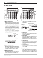
AD Input Section
1 INPUT connectors A/B
INPUT A connectors are balanced XLR-3-31-type
connectors that accept line-level and microphone
signals. Each of the phantom [+48V] switches on
the rear panel turns on or off the +48V phantom
power feed to the corresponding input. INPUT B
connectors are balanced TRS phone-type connec-
tors that accept line-level and microphone signals.
The nominal signal level of both types of connec-
tors ranges from –60 dB to +4 dB. Phantom power
is not supplied to these connectors.
If you connect cables to INPUT A and INPUT B
connectors of the same number, only the signal
from INPUT B is effective.
2 INPUT connectors 13–16
These balanced TRS phone-type connectors accept
line-level signals. The nominal signal level ranges
from –26 dB to +4 dB. INPUT 15 & 16 connectors
are available only when the AD 15/16 button is
turned off.
3 INSERT I/O connectors
These unbalanced TRS phone-type connectors are
used for channel insert ins and outs. Use a split
cable to insert an external effects processor to AD
input channels.
4 PAD switches
These switches turn on or off the 20 dB pad (atten-
uator) for each AD Input.
5 GAIN controls
These controls adjust input sensitivity for each AD
Input. Input sensitivity is –16 dB to –60 dB when
the Pad is off, and +4 dB to –40 dB when the Pad is
on.
6 PEAK indicators
These indicators light up when the input signal level
is 3 dB below clipping. Adjust the Pad switch and
GAIN control so that the indicator rarely lights up
at signal peak.
7 SIGNAL indicators
These indicators light up when the input signal level
exceeds –34 dB.
8 AD15/16 selector
This button selects AD Input Channel 15 and 16
signals. When the button is turned on (pushed in),
the 2TR IN signals (page 17) are selected. When the
button is turned off (raised), the INPUT 15 and 16
signals are selected.
PEAK
SIGNAL
PEAK
SIGNAL
PEAK
SIGNAL
PEAK
SIGNAL
PEAK
SIGNAL
PEAK
SIGNAL
PEAK
SIGNAL
PEAK
SIGNAL
PEAK
SIGNAL
PEAK
SIGNAL
PEAK
SIGNAL
CH15
/
16
2TR IN
+4
-26
GAIN
+4
-26
GAIN
+4
-26
GAIN
GAIN
+4
-26
GAIN
20dB
-16 -60
GAIN
20dB
-16 -60
GAIN
20dB20dB20dB20dB20dB20dB20dB
-16 -60
GAIN
-16 -60
GAIN
-16 -60
GAIN
-16 -60
GAIN
-16 -60
GAIN
-16 -60
GAIN
-16 -60
PAD
A
B
A
B
A
B
A
B
A
B
A
B
A
B
A
B
A
B
16
1513
121110943215
14
INSERT I
/
O INSERT I
/
O INSERT I
/
O INSERT I
/
O INSERT I
/
O INSERT I
/
O INSERT I
/
O INSERT I
/
O INSERT I
/
O
CH1-4
INPUT
(BAL)
INSERT
OUT IN
(UNBAL)
13 14 15 16
1
3
4
5
6
7
8
2
1/4" TRS phone plug
Ring (cold)
Sleeve (ground)
Tip (hot)
Male XLR plug
1 (ground)
2 (hot)
3 (cold)
1/4" phone
plug
1/4" phone plug
Sleeve (ground)
Tip (send)
Sleeve
(ground)
Connect to
INSERT jack
Tip (return)
1/4" phone plug
Tip (send)
Ring (return)
Sleeve (ground)
From processor’s output
To processor’s input

Control Surface 11
01V96i—Owner’s Manual
Control Surface
& Rear Panel
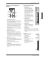
Monitor Out & Headphones
Section
1 2TR IN/OUT connectors
These unbalanced RCA phono connectors input
and output line-level signals, and are typically used
to connect an external recorder.
When the AD15/16 selector in the AD Input sec-
tion (
8) is turned on (pushed in), the signals input
at the 2TR IN connectors are routed to AD Input
Channels 15 and 16. When the Monitor Source
selector (
2) is turned on (pushed in), you can
monitor the 2TR IN signals from the MONITOR
OUT connectors.
The 2TR OUT signals are always the same as the
STEREO OUT signals.
2 Monitor Source selector
This button selects the signals output from the
MONITOR OUT connectors on the rear panel.
When this button is turned on (pushed in), you can
monitor the signals input from the 2TR IN connec-
tors. When the button is turned off (raised), you can
monitor the Stereo Out signals or soloed channel
signals.
3 MONITOR LEVEL control
This control adjusts the monitoring level of the sig-
nals output from the MONITOR OUT connectors.
4 PHONES LEVEL control
This control sets the level of the PHONES.
5 PHONES jack
You can connect a set of stereo headphones to this
stereo phone jack. The signals output from the
MONITOR OUT connectors are also output from
this jack.
Channel Strip Section
1 [SEL] buttons
These buttons enable you to
select desired channels. The
[SEL] button indicator for the
currently-selected channel lights
up. The channel selected by each
[SEL] button depends on the
layer selected in the LAYER sec-
tion (see page 13).
These buttons also allow you to
create or cancel channel pairs,
and add channels to (or remove
them from) Fader, Mute, EQ, and
Compressor groups.
2 [SOLO] buttons
These buttons solo the selected
channels. The [SOLO] button
indicator of the currently-soloed
channel lights up.
3 [ON] buttons
These buttons turn the selected
channels on or off. The [ON]
button indicators for On chan-
nels light up.
4 Channel faders
Depending on the button selected in the FADER
MODE section (see page 12), these faders adjust the
selected channel input levels or the Bus Out or Aux
Out levels.
STEREO Section
1 [SEL] button
Selects the Stereo Out.
2 [ON] button
Turns the Stereo Out on or off.
3 [STEREO] fader
This 100mm motorized fader
adjusts the final output level of
the Stereo Out.
PHONES
MONITOR
OUT
MONITOR
2TR IN
LEVEL
PHONES
LEVEL
0
10
0
10
L
R
IN OUT
2TR
-10dBV
(UNBAL)
PHANTOM +48V
CH9-12CH5-8
1
2
3
4
5
SOLO
ON
SEL
AUX 1
40
50
60
70
30
5
10
15
20
0
20
30
40
50
15
5
+10
5
10
0
1
1
17
1
2
3
4
ON
SEL
5
10
15
20
30
40
50
60
70
0
STEREO
1
2
3

12 Control Surface & Rear Panel
01V96i—Owner’s Manual
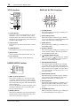
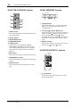
ST IN Section
1 [ST IN] button
This button selects an ST IN channel pair (ST IN
Channels 1 & 2 or 3 & 4) which you can control
using the buttons and controls in the ST IN section.
The indicators to the right of the button indicate the
available ST IN channels.
2 [SEL] buttons
These buttons select the ST IN channel you want to
control.
3 [SOLO] buttons
These buttons solo the selected ST IN channels.
4 [ON] buttons
These buttons turn the ST IN channels on or off.
5 Level controls
These controls adjust the ST IN channel levels.
FADER MODE Section
1 [AUX 1]–[AUX 8] buttons
These buttons enable you to select the Aux Send
you wish to control. Pressing one of these buttons
switches the Fader mode (see page 22), and displays
the corresponding Aux page. (The selected button’s
indicator lights up.)
You can now adjust the send level of signals routed
from Input Channels to the corresponding Aux
buses by using the faders.
2 [HOME] button
This button recalls Meter pages that display Input
Channel levels or Output Channel (Bus Out, Aux
Out, Stereo Out) levels (see page 23).
DISPLAY ACCESS Section
1 [SCENE] button
This button displays a Scene page, enabling you to
store and recall Scenes.
2 [DIO/SETUP] button
This button displays a DIO/Setup page, enabling
you to set up the 01V96i, including digital input and
output setup and remote control setup.
3 [MIDI] button
This button displays a MIDI page, enabling you to
make MIDI settings.
4 [UTILITY] button
This button displays a Utility page, enabling you to
use the internal oscillators and view information
about installed optional cards.
5 [ /INSERT/DELAY] button
This button displays a /INS/DLY page, enabling
you to switch the signal phase, set the signal to be
inserted, or set the delay parameters.
6 [PAN/ROUTING] button
This button displays a Pan/Route page, enabling
you to select a Bus to which the selected channel
signal is routed, adjust the selected channel pan set-
tings, adjust the level of signals routed from Buses
1–8 to the Stereo Bus, and adjust the stereo or sur-
round pan settings.
7 [PAIR/GROUP] button
This button displays a Pair/Group page, enabling
you to create or cancel channel pairs and group
multiple channel faders or [ON] buttons.
8 [PATCH] button
This button displays a Patch page, enabling you to
patch input signals and Bus Out signals to Input
channels, or patch signals to the desired output con-
nectors.
9 [DYNAMICS] button
This button displays a Dynamics page, enabling you
to control channel gates and compressors.
SOLO
ON
SOLO
ON
SEL SEL
ST IN
ST IN 1 ST IN 2
1
2
3
4
5
FADER MODE
AUX
1
AUX
2
AUX
3
AUX
4
AUX
8
AUX
7
AUX
6
AUX
5
HOME (METER)
1
2
DISPLAY ACCESS
DYNAMICS
EQ EFFECT VIEW
PATCH
UTILITYMIDISCENE
DIO/SETUP
/ INSERT/
DELAY
PAN/
ROUTING
PAIR/
GROUP
1 2 3
9
0 A B
4
5
6
8
7
UTILITYMIDISCENE
DIO/SETUP

Control Surface 13
01V96i—Owner’s Manual
Control Surface
& Rear Panel
0 [EQ] button
This button displays an EQ page, enabling you to set
the equalizer and attenuator of the selected channel.
A [EFFECT] button
This button displays an Effect page, enabling you to
edit the internal effects processors and use optional
plug-in cards.
B [VIEW] button
This button displays a View page, enabling you to
view and set mix parameters for a specific channel.
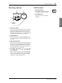
LAYER Section
1 [1–16]/[17–32] buttons
These buttons select an Input Channel layer as the
layer controlled in the Channel Strip section. When
the [1–16] button is turned on, you can control
Channels 1–16. When the [17–32] button is turned
on, you can control Channels 17–32. (See page 21
for more information on the Input Channel layers.)
2 [MASTER] button
This button selects the Master Layer as the layer
controlled in the Channel Strip section. You can use
this layer to control Bus Outs and AUX Sends. (See
page 21 for more information on the Master layer.)
3 [REMOTE] button
This button selects the Remote Layer as the layer
controlled in the Channel Strip section. You can use
this layer to control external MIDI devices or com-
puter-based DAWs.
Display Section
1 Display
This is a 320 x 240 dot LCD display with a backlight.
2 Stereo meters
These 12-segment level meters display the final out-
put level of the Stereo Bus.
3 Contrast control
This control adjusts the display contrast.
4 [F1]–[F4] buttons
These buttons select a page from a multi-page
screen. Selecting a tab at the bottom of the screen
using one of these buttons displays the correspond-
ing page. (See page 20 for more information on dis-
playing a page.)
5 Left Tab Scroll [ ] button
6 Right Tab Scroll [ ] button
If there are more pages available than the four
whose tabs are currently displayed, use these but-
tons to display the additional tabs. These buttons
are available only when the left or right Tab Scroll
arrow appears.
Tip: The ST IN section is not affected by the layer settings.
1-16 17-32 MASTER REMOTE
LAYER
1 2 3
STEREO
OVER
0
-3
-6
-9
-12
-15
-18
-24
-30
-36
-48
4
1
5
2
3
6
Tab Scroll arrow

14 Control Surface & Rear Panel
01V96i—Owner’s Manual
SELECTED CHANNEL Section
1 [PAN] control
This control adjusts the pan of the channel selected
by the [SEL] button.
2 [HIGH] button
3 [HIGH-MID] button
4 [LOW-MID] button
5 [LOW] button
These buttons select the EQ band (HIGH,
HIGH-MID, LOW-MID, LOW) of the channel
selected by the [SEL] button. The corresponding
button indicator of the currently-selected band
lights up.
6 [Q] control
This control adjusts the currently-selected band Q.
7 [FREQUENCY] control
This control adjusts the currently-selected band fre-
quency.
8 [GAIN] control
This control adjusts the currently-selected band
gain.
SCENE MEMORY Section
1 [STORE] button
This button enables you to store the current mix
settings. (See page 42 for more information on
Scene Memories.)
2 Scene Up [ ] / Down [ ] buttons
These buttons select a Scene to store or recall. Press-
ing the Scene Up [ ] button increments the selec-
tion; pressing the Scene Down [ ] button
decrements the selection. Holding down either key
increments or decrements the selection continu-
ously.
3 [RECALL] button
This button recalls the Scene memory selected by
the Scene Up [ ] / Down [ ] buttons.
USER DEFINED KEYS Section
1 [1]–[8] buttons
You can assign any of the 167 functions to these
User Defined buttons.
HIGH
HIGH-MID
LOW-MID
LOW
Q
FREQUENCY
GAIN
2
3
4
5
6
1
7
8
RECALL
STORE
SCENE MEMORY
2
13
USER DEFINED
KEYS
12
34
56
78
1

Control Surface 15
01V96i—Owner’s Manual
Control Surface
& Rear Panel
Data Entry Section
1 Parameter wheel
This control adjusts the parameter values shown on
the display. Turning it clockwise increases the value;
turning it counterclockwise decreases the value.
This wheel also enables you to scroll a displayed list
and select a character for entry (see page 21).
2 [ENTER] button
This button activates a selected (highlighted) but-
ton on the display, and confirms the edited param-
eter values.
3 [DEC]/[INC] buttons
These buttons increment or decrement a parameter
value by one. Pressing the [INC] button increments
the value; pressing the [DEC] button decrements
the value. Holding down either key increments or
decrements the value continuously.
4 Left, Right, Up, Down ([ ]/[ ]/[ ]/[ ])
cursor buttons
These buttons move the cursor around the display
pages, or select parameters and options. Holding
down a cursor button moves the cursor continu-
ously in the corresponding direction.
SOLO Section
1 [SOLO] indicator
This indicator flashes when single
or multiple channels are soloed.
2 [CLEAR] button
This button “unsolos” all soloed
Channels.
ENTER
DEC INC
2
3
1
4
SOLO CLEAR
1 2

16 Control Surface & Rear Panel
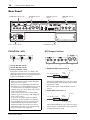
01V96i—Owner’s Manual
Rear Panel
PHANTOM +48V
1 CH1–4 ON/OFF switch
2 CH5–8 ON/OFF switch
3 CH9–12 ON/OFF switch
Each of these switches turns on or off the +48V
phantom power feed to four corresponding inputs.
When the switches are on, +48V phantom power is
supplied to the INPUT A connectors.
AD Output Section
1 MONITOR OUT connectors L/R
These balanced TRS phone-type connectors output
monitoring signals or 2TR IN signals. The nominal
signal level is +4 dB.
You can select signals using the Monitor Source
selector.
2 OMNI OUT connectors 1–4
These balanced TRS phone-type connectors output
any Bus signals or channel Direct Out signals. The
nominal signal level is +4 dB.
PHANTOM +48V (p. 16)
Power Section (p. 18)
AD Output Section
(p. 16)
SLOT Section (p. 18)
MIDI/USB Section
(p. 17)
Digital I/O Section
(p. 17)
Note:
• Make sure that this switch is turned off if phan-
tom power is not required.
• Before you turn on phantom power, make sure
that only devices requiring phantom power (such
as condenser mics) are connected. Supplying
phantom power to a device that does not require
it will cause malfunctions.
• Do not connect or disconnect a device while
phantom power is on. Doing so will damage the
device or the console.
• To protect your speakers, make sure that the
power amps (powered speakers) are off before
you turn phantom power on or off. We also rec-
ommend that all output level faders be mini-
mized. If you fail to observe these precautions,
high volume output may occur, possibly damag-
ing your hearing or your equipment.
321
321
1/4" TRS phone plug
Ring
(cold)
Sleeve (ground)
Tip (hot)
1/4" TRS phone plug
Ring
(cold)
Sleeve (ground)
Tip (hot)

Rear Panel 17
01V96i—Owner’s Manual
Control Surface
& Rear Panel
3 STEREO OUT connectors L/R
These balanced XLR-3-32-type connectors output
the Stereo Out signals. The nominal signal level is
+4 dB.
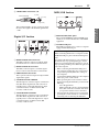
Digital I/O Section
1 WORD CLOCK OUT connector
This BNC connector outputs a wordclock signal
from the 01V96i to a connected external device.
2 WORD CLOCK IN connector
This BNC connector inputs a wordclock signal
from a connected external device to the 01V96i.
3 ADAT IN/OUT connectors
These optical connectors input and output ADAT
digital audio signals.
4 2TR OUT DIGITAL COAXIAL
This RCA phono connector outputs consumer for-
mat (IEC 60958) digital audio. The connector is
typically used to connect the digital stereo input
(consumer format) of a DAT recorder, MD
recorder, or CD recorder.
5 2TR IN DIGITAL COAXIAL
This RCA phono connector accepts consumer for-
mat (IEC 60958) digital audio. The connector is
typically used to connect the digital stereo output
(consumer format) of a DAT recorder, MD
recorder, or CD recorder.
MIDI/USB Section
1 MIDI IN/THRU/OUT ports
These standard MIDI IN, OUT and THRU ports
enable you to connect the 01V96i to other MIDI
equipment.
2 TO HOST USB port
This USB port enables you to connect a computer
equipped with a USB 2.0 port.
Female XLR plug
1 (ground)
2 (hot)
3 (cold)
42153
Note when using the TO HOST USB port
When connecting the 01V96i to a computer via the
TO HOST USB port, please take the following mea-
sures.
If you fail to take these measures, your computer or
the 01V96i may stop operating (hang up), or data
may be lost or damaged. If the computer or console
stops operating, turn the power off and on again, and
reboot the computer.
• Before connecting the TO HOST USB port to
your computer, disable the power conservation
(suspend/sleep/standby/hibernate) settings of
your computer.
• Connect the TO HOST USB port to the computer
before you power-on the console.
• Before powering the console on/off or connect-
ing/disconnecting the USB cable, you must do the
following.
- Close all applications.
- Make sure that the console is not transmitting
data. (The console also transmits data when
you operate its buttons or move its faders.)
• Leave an interval of at least six seconds between
powering the console off and on, or between dis-
connecting and reconnecting the USB cable.
21

18 Control Surface & Rear Panel
01V96i—Owner’s Manual
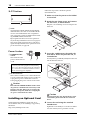
SLOT Section
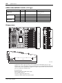
1 SLOT
Optional mini-YGDAI (Yamaha General Digital
Audio Interface) I/O cards can be installed in this
slot. You can install AD/DA cards or digital I/O
cards supporting a variety of digital formats includ-
ing AES/EBU, ADAT, and Tascam.
Input signals from an I/O card can be patched to
any desired input channel or insert-in (see page 29).
The output signal of any desired bus or the direct
signal of an input channel can be patched to an out-
put of an I/O card (see page 30).
Power Section
1 POWER ON/OFF
switch
This switch turns the
power to the 01V96i on
or off.
2 AC IN connector
This connector enables you to connect the 01V96i
to an AC outlet via the supplied power cord. Be sure
to plug the AC power cord into this connector
before plugging the power cord into an AC outlet.
Caution
Even when the POWER ON/OFF switch is in the
off position, a small amount of electricity is still
flowing to the unit. When you are not using the
01V96i for a long time, make sure to unplug the
AC power cord from the AC outlet.
Installing an Optional Card
Visit the following Yamaha Pro Audio web site to
ensure that the card you are installing is supported by
the 01V96i.
http://www.yamahaproaudio.com/
Follow the steps below to install an optional
mini-YGDAI card.
1. Make sure that the power to the 01V96i
is turned off.
2. Undo the two fixing screws and remove
the slot cover, as shown below.
Keep the cover and fixing screws in a safe place for
future use.
3. Insert the card between the guide rails
and slide it all the way into the slot, as
shown below.
You may have to push firmly to fully insert the card
into the internal connector.
Caution
When inserting the card, align both sides of the
card with the guide rails in the slot of the host
device.
4. Secure the card using the attached
thumbscrews.
Tighten the screws firmly to secure the card. Other-
wise, the card may not be grounded correctly.
Note: To prevent loud clicks and thumps in your speak-
ers, turn on your audio equipment in the following
order (reverse this order when turning the equipment
off)—sound sources, multitrack and master recorders,
01V96i, monitoring power amplifiers.
1
21

Operating Basics 19
01V96i—Owner’s Manual
Operating Basics
Operating Basics
This chapter describes basic operations on the 01V96i,
including how to use the display and operate the con-
trols on the top panel.
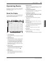
About the Display
The top panel display indicates various parameters that
you must set before you can operate the 01V96i. The
display indicates the following items:
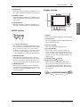
1 Selected DISPLAY
This section indicates the currently-selected display
page group.
2 Selected channel
This section indicates the Input or Output Channel
currently selected by its corresponding [SEL] but-
ton. The first four characters are the Channel ID
(e.g., CH1–CH32, BUS1–BUS8, AUX1–AUX8,
ST-L, ST-R). The second four characters are the
channel’s Short name. You can edit the short name
if you desire (see page 43).
3 Current Scene
This section indicates the number and title of the
currently-selected Scene memory. If the selected
Scene is write-protected, a padlock icon ( )
appears.
4 EDIT indicator
This indicator appears when the current mix set-
tings no longer match those of the Scene that was
most-currently recalled.
5 MIDI indicator
This indicator appears when the 01V96i is receiving
MIDI data via the MIDI IN port, USB port, or an
installed card.
6 Surround mode indicator
This indicator identifies the currently-selected Sur-
round mode (ST=stereo, 3-1, 5.1, or 6.1).
7 Sampling rate indicator
This indicator identifies the 01V96i’s current sam-
pling rate: 44.1 kHz (44k), 48 kHz (48k), 88.2 kHz
(88k), or 96 kHz (96k).
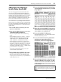
8 ST IN channel levels
These level controls indicate the level of ST IN
channels 1–4.
9 Page title
This section indicates the title of the current page.
0 Channel name
On certain pages, this area displays the Long name
of the channel currently selected by the [SEL] key or
the channel selected by the cursor keys.
A Page area
This page area displays various page contents.
B Page tabs
These tabs enable you to select a display page.
C Tab Scroll arrows
These arrows indicate that more pages are available.
843 5 672
9
10
CBA

20 Operating Basics
01V96i—Owner’s Manual
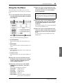
Selecting Display Pages
To select a display page:
1. Press the corresponding button on the
top panel to select the desired page
group.
Display pages are grouped by function. To select a
page group, press the desired button in the DIS-
PLAY ACCESS section.
2. You can select pages that have cur-
rently-displayed tabs by pressing the
[F1]–[F4] buttons.
If the selected display page group contains multiple
pages, press the [F1]–[F4] buttons below the corre-
sponding tab to select a specific page.
3. To select a page for which a tab is not cur-
rently displayed, press either the Left or
Right [ ]/[ ] Tab Scroll button
(depending on where the page is
located) to display the page tab, then
press the corresponding [F1]–[F4] but-
ton.
If display page groups contain more than four
pages, either the left or right arrow appears. To dis-
play the currently-hidden tabs, press the Right or
Left [ ]/[ ] Tab Scroll button.
You can also select a page from a page group as fol-
lows:
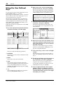
• Selecting the next page in a page group:
Press the button you selected in Step 1 repeatedly.
This enables you to select a page that has a hidden
tab.
• To select the previous page in a page group:
Press and hold down the button you selected in Step
1. The screen steps back through the pages one by
one. Release the button when the desired page is
displayed. This enables you to select a page that has
a hidden tab.
• To select the first page in the group:
Double-click the button you selected in Step 1.
4. Press the cursor buttons to move the cur-
sor (a bold frame) to a button, parameter
box, rotary control, or fader so that you
can change the value.
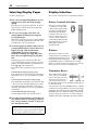
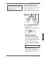
Display Interface
This section describes how to use the display interface.
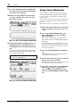
Rotary Controls & Faders
The rotary controls and fad-
ers enable you to adjust the
continuously variable param-
eter values, including Input
Channel levels and effects
parameters. Press the cursor
buttons to move the cursor to
a rotary control or fader you
want to adjust, then rotate the
Parameter wheel or press the
[INC]/[DEC] buttons to
modify the value.
Buttons
The buttons enable you to turn
certain functions on (enabled) or
off (disabled). Move the cursor to
the appropriate button, then press
the [ENTER] button to turn the function on (high-
lighted) or off. The buttons also enable you to select one
of two options or to execute certain functions.
Parameter Boxes
The parameter boxes enable
you to select one of multiple
options. Press the cursor but-
tons to move the cursor to a
parameter box, then rotate
the Parameter wheel or press the [INC]/[DEC] buttons
to select the setting.
You may need to press the [ENTER] button to confirm
a change in certain parameter boxes. If you edit a value
in this type of parameter box, the value flashes. Press the
[ENTER] button to confirm the change, and the flash-
ing stops. If you move the cursor to other parameters
while the edited value is flashing, the edit is cancelled.
Tip: The 01V96i remembers the current page and
parameter when you select a new page group. If you
return to the previous page group, the 01V96i displays
the correct page, with the same parameter selected.
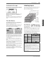
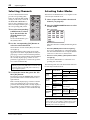
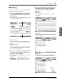
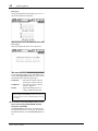
La page est en cours de chargement...
La page est en cours de chargement...
La page est en cours de chargement...
La page est en cours de chargement...
La page est en cours de chargement...
La page est en cours de chargement...
La page est en cours de chargement...
La page est en cours de chargement...
La page est en cours de chargement...
La page est en cours de chargement...
La page est en cours de chargement...
La page est en cours de chargement...
La page est en cours de chargement...
La page est en cours de chargement...
La page est en cours de chargement...
La page est en cours de chargement...
La page est en cours de chargement...
La page est en cours de chargement...
La page est en cours de chargement...
La page est en cours de chargement...
La page est en cours de chargement...
La page est en cours de chargement...
La page est en cours de chargement...
La page est en cours de chargement...
La page est en cours de chargement...
La page est en cours de chargement...
La page est en cours de chargement...
La page est en cours de chargement...
La page est en cours de chargement...
La page est en cours de chargement...
La page est en cours de chargement...
La page est en cours de chargement...
La page est en cours de chargement...
La page est en cours de chargement...
La page est en cours de chargement...
La page est en cours de chargement...
La page est en cours de chargement...
La page est en cours de chargement...
La page est en cours de chargement...
La page est en cours de chargement...
La page est en cours de chargement...
La page est en cours de chargement...
La page est en cours de chargement...
La page est en cours de chargement...
La page est en cours de chargement...
La page est en cours de chargement...
La page est en cours de chargement...
La page est en cours de chargement...
La page est en cours de chargement...
La page est en cours de chargement...
La page est en cours de chargement...
-
 1
1
-
 2
2
-
 3
3
-
 4
4
-
 5
5
-
 6
6
-
 7
7
-
 8
8
-
 9
9
-
 10
10
-
 11
11
-
 12
12
-
 13
13
-
 14
14
-
 15
15
-
 16
16
-
 17
17
-
 18
18
-
 19
19
-
 20
20
-
 21
21
-
 22
22
-
 23
23
-
 24
24
-
 25
25
-
 26
26
-
 27
27
-
 28
28
-
 29
29
-
 30
30
-
 31
31
-
 32
32
-
 33
33
-
 34
34
-
 35
35
-
 36
36
-
 37
37
-
 38
38
-
 39
39
-
 40
40
-
 41
41
-
 42
42
-
 43
43
-
 44
44
-
 45
45
-
 46
46
-
 47
47
-
 48
48
-
 49
49
-
 50
50
-
 51
51
-
 52
52
-
 53
53
-
 54
54
-
 55
55
-
 56
56
-
 57
57
-
 58
58
-
 59
59
-
 60
60
-
 61
61
-
 62
62
-
 63
63
-
 64
64
-
 65
65
-
 66
66
-
 67
67
-
 68
68
-
 69
69
-
 70
70
-
 71
71


Yamaha 01V96 Le manuel du propriétaire
- Catégorie
- Mélangeurs audio
- Taper
- Le manuel du propriétaire
- Ce manuel convient également à
dans d''autres langues
- italiano: Yamaha 01V96 Manuale del proprietario
- English: Yamaha 01V96 Owner's manual
- español: Yamaha 01V96 El manual del propietario
- Deutsch: Yamaha 01V96 Bedienungsanleitung
- русский: Yamaha 01V96 Инструкция по применению
- Nederlands: Yamaha 01V96 de handleiding
- português: Yamaha 01V96 Manual do proprietário
- dansk: Yamaha 01V96 Brugervejledning
- polski: Yamaha 01V96 Instrukcja obsługi
- čeština: Yamaha 01V96 Návod k obsluze
- svenska: Yamaha 01V96 Bruksanvisning
- Türkçe: Yamaha 01V96 El kitabı
- suomi: Yamaha 01V96 Omistajan opas
- română: Yamaha 01V96 Manualul proprietarului
Documents connexes
-
Yamaha TF-RACK Guide de démarrage rapide
-
Yamaha V96i Manuel utilisateur
-
-
Yamaha Audiogram3 Le manuel du propriétaire
-
-
Yamaha TF3 Mode d'emploi
-
-
-
-