Lincoln Electric Commander 500 Mode d'emploi
- Catégorie
- Système de soudage
- Taper
- Mode d'emploi

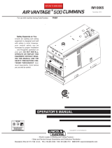
Commander 500 Cummins
OPERATOR’S MANUAL
IM765
March, 2002
Safety Depends on You
Lincoln arc welding and cutting
equipment is designed and built
with safety in mind. However, your
overall safety can be increased by
proper installation ... and thoughtful
operation on your part. DO NOT
INSTALL, OPERATE OR REPAIR
THIS EQUIPMENT WITHOUT
READING THIS MANUAL AND
THE SAFETY PRECAUTIONS
CONTAINED THROUGHOUT. And,
most importantly, think before you
act and be careful.
For use with machines having Code Numbers:
10903 (Standard),
10904 (Deluxe)
™
Date of Purchase:
Serial Number:
Code Number:
Model:
Where Purchased:
• Sales and Service through Subsidiaries and Distributors Worldwide •
Cleveland, Ohio 44117-1199 U.S.A. TEL: 216.481.8100 FAX: 216.486.1751 WEB SITE: www.lincolnelectric.com
• World's Leader in Welding and Cutting Products •
Copyright © 2002 Lincoln Global Inc.
This manual covers equipment which is no
longer in production by The Lincoln Electric Co.
Specications and availability of optional
features may have changed.

FOR ENGINE
powered equipment.
1.a. Turn the engine off before troubleshooting and maintenance
work unless the maintenance work requires it to be running.
____________________________________________________
1.b.Operate engines in open, well-ventilated
areas or vent the engine exhaust fumes
outdoors.
____________________________________________________
1.c. Do not add the fuel near an open flame weld-
ing arc or when the engine is running. Stop
the engine and allow it to cool before refuel-
ing to prevent spilled fuel from vaporizing on
contact with hot engine parts and igniting. Do
not spill fuel when filling tank. If fuel is spilled,
wipe it up and do not start engine until fumes
have been eliminated.
____________________________________________________
1.d. Keep all equipment safety guards, coversand devices in posi-
tion and in good repair.Keep hands, hair, clothing and tools
away from V-belts, gears, fans and all other moving parts
when starting, operating or repairing equipment.
____________________________________________________
1.e. In some cases it may be necessary to remove safety
guards to perform required maintenance. Remove
guards only when necessary and replace them when the
maintenance requiring their removal is complete.
Always use the greatest care when working near moving
parts.
___________________________________________________
1.f. Do not put your hands near the engine fan.
Do not attempt to override the governor or
idler by pushing on the throttle control rods
while the engine is running.
___________________________________________________
1.g. To prevent accidentally starting gasoline engines while
turning the engine or welding generator during maintenance
work, disconnect the spark plug wires, distributor cap or
magneto wire as appropriate.
i
SAFETY
i
ARC WELDING CAN BE HAZARDOUS. PROTECT YOURSELF AND OTHERS FROM POSSIBLE SERIOUS INJURY OR DEATH.
KEEP CHILDREN AWAY. PACEMAKER WEARERS SHOULD CONSULT WITH THEIR DOCTOR BEFORE OPERATING.
Read and understand the following safety highlights. For additional safety information, it is strongly recommended that you
purchase a copy of “Safety in Welding & Cutting - ANSI Standard Z49.1” from the American Welding Society, P.O. Box 351040,
Miami, Florida 33135 or CSA Standard W117.2-1974. A Free copy of “Arc Welding Safety” booklet E205 is available from the
Lincoln Electric Company, 22801 St. Clair Avenue, Cleveland, Ohio 44117-1199.
BE SURE THAT ALL INSTALLATION, OPERATION, MAINTENANCE AND REPAIR PROCEDURES ARE
PERFORMED ONLY BY QUALIFIED INDIVIDUALS.
WARNING
Mar ‘95
ELECTRIC AND
MAGNETIC FIELDS
may be dangerous
2.a. Electric current flowing through any conductor causes
localized Electric and Magnetic Fields (EMF). Welding
current creates EMF fields around welding cables and
welding machines
2.b. EMF fields may interfere with some pacemakers, and
welders having a pacemaker should consult their physician
before welding.
2.c. Exposure to EMF fields in welding may have other health
effects which are now not known.
2.d. All welders should use the following procedures in order to
minimize exposure to EMF fields from the welding circuit:
2.d.1.
Route the electrode and work cables together - Secure
them with tape when possible.
2.d.2. Never coil the electrode lead around your body.
2.d.3. Do not place your body between the electrode and
work cables. If the electrode cable is on your right
side, the work cable should also be on your right side.
2.d.4. Connect the work cable to the workpiece as close as
possible to the area being welded.
2.d.5. Do not work next to welding power source.
1.h. To avoid scalding, do not remove the
radiator pressure cap when the engine is
hot.
For Diesel Engines: Diesel engine exhaust and
some of its constituents are known to the State
of California to cause cancer, birth defects, and
other reproductive harm.
For Gasoline Engines: The engine exhaust from
this product contains chemicals known to the
State of California to cause cancer, birth defects,
or other reproductive harm.
CALIFORNIA PROPOSITION 65 WARNINGS

ii
SAFETY
ii
ARC RAYS can burn.
4.a. Use a shield with the proper filter and cover
plates to protect your eyes from sparks and
the rays of the arc when welding or observing
open arc welding. Headshield and filter lens
should conform to ANSI Z87. I standards.
4.b. Use suitable clothing made from durable flame-resistant
material to protect your skin and that of your helpers from
the arc rays.
4.c. Protect other nearby personnel with suitable, non-flammable
screening and/or warn them not to watch the arc nor expose
themselves to the arc rays or to hot spatter or metal.
ELECTRIC SHOCK can kill.
3.a. The electrode and work (or ground) circuits
are electrically “hot” when the welder is on.
Do not touch these “hot” parts with your bare
skin or wet clothing. Wear dry, hole-free
gloves to insulate hands.
3.b. Insulate yourself from work and ground using dry insulation.
Make certain the insulation is large enough to cover your full
area of physical contact with work and ground.
In addition to the normal safety precautions, if welding
must be performed under electrically hazardous
conditions (in damp locations or while wearing wet
clothing; on metal structures such as floors, gratings or
scaffolds; when in cramped positions such as sitting,
kneeling or lying, if there is a high risk of unavoidable or
accidental contact with the workpiece or ground) use
the following equipment:
• Semiautomatic DC Constant Voltage (Wire) Welder.
• DC Manual (Stick) Welder.
• AC Welder with Reduced Voltage Control.
3.c. In semiautomatic or automatic wire welding, the electrode,
electrode reel, welding head, nozzle or semiautomatic
welding gun are also electrically “hot”.
3.d. Always be sure the work cable makes a good electrical
connection with the metal being welded. The connection
should be as close as possible to the area being welded.
3.e. Ground the work or metal to be welded to a good electrical
(earth) ground.
3.f.
Maintain the electrode holder, work clamp, welding cable and
welding machine in good, safe operating condition. Replace
damaged insulation.
3.g. Never dip the electrode in water for cooling.
3.h. Never simultaneously touch electrically “hot” parts of
electrode holders connected to two welders because voltage
between the two can be the total of the open circuit voltage
of both welders.
3.i. When working above floor level, use a safety belt to protect
yourself from a fall should you get a shock.
3.j. Also see Items 6.c. and 8.
FUMES AND GASES
can be dangerous.
5.a. Welding may produce fumes and gases
hazardous to health. Avoid breathing these
fumes and gases.When welding, keep
your head out of the fume. Use enough
ventilation and/or exhaust at the arc to keep
fumes and gases away from the breathing zone. When
welding with electrodes which require special
ventilation such as stainless or hard facing (see
instructions on container or MSDS) or on lead or
cadmium plated steel and other metals or coatings
which produce highly toxic fumes, keep exposure as
low as possible and below Threshold Limit Values (TLV)
using local exhaust or mechanical ventilation. In
confined spaces or in some circumstances, outdoors, a
respirator may be required. Additional precautions are
also required when welding on galvanized steel.
5.b.
Do not weld in locations near chlorinated hydrocarbon
vapors
coming from degreasing, cleaning or spraying operations.
The heat and rays of the arc can react with solvent vapors
to
form phosgene, a highly toxic gas, and other irritating
products.
5.c. Shielding gases used for arc welding can displace air and
cause injury or death. Always use enough ventilation,
especially in confined areas, to insure breathing air is safe.
5.d. Read and understand the manufacturer’s instructions for this
equipment and the consumables to be used, including the
material safety data sheet (MSDS) and follow your
employer’s safety practices. MSDS forms are available from
your welding distributor or from the manufacturer.
5.e. Also see item 1.b.
Mar ‘95

FOR ELECTRICALLY
powered equipment.
8.a. Turn off input power using the disconnect
switch at the fuse box before working on
the equipment.
8.b. Install equipment in accordance with the U.S. National
Electrical Code, all local codes and the manufacturer’s
recommendations.
8.c. Ground the equipment in accordance with the U.S. National
Electrical Code and the manufacturer’s recommendations.
CYLINDER may explode
if damaged.
7.a. Use only compressed gas cylinders
containing the correct shielding gas for the
process used and properly operating
regulators designed for the gas and
pressure used. All hoses, fittings, etc. should be suitable for
the application and maintained in good condition.
7.b. Always keep cylinders in an upright position securely
chained to an undercarriage or fixed support.
7.c. Cylinders should be located:
• Away from areas where they may be struck or subjected to
physical damage.
• A safe distance from arc welding or cutting operations and
any other source of heat, sparks, or flame.
7.d. Never allow the electrode, electrode holder or any other
electrically “hot” parts to touch a cylinder.
7.e. Keep your head and face away from the cylinder valve outlet
when opening the cylinder valve.
7.f. Valve protection caps should always be in place and hand
tight except when the cylinder is in use or connected for
use.
7.g. Read and follow the instructions on compressed gas
cylinders, associated equipment, and CGA publication P-l,
“Precautions for Safe Handling of Compressed Gases in
Cylinders,” available from the Compressed Gas Association
1235 Jefferson Davis Highway, Arlington, VA 22202.
iii
SAFETY
iii
Mar ‘95
WELDING SPARKS can
cause fire or explosion.
6.a.
Remove fire hazards from the welding area.
If this is not possible, cover them to prevent
the welding sparks from starting a fire.
Remember that welding sparks and hot
materials from welding can easily go through small cracks
and openings to adjacent areas. Avoid welding near
hydraulic lines. Have a fire extinguisher readily available.
6.b. Where compressed gases are to be used at the job site,
special precautions should be used to prevent hazardous
situations. Refer to “Safety in Welding and Cutting” (ANSI
Standard Z49.1) and the operating information for the
equipment being used.
6.c. When not welding, make certain no part of the electrode
circuit is touching the work or ground. Accidental contact can
cause overheating and create a fire hazard.
6.d. Do not heat, cut or weld tanks, drums or containers until the
proper steps have been taken to insure that such procedures
will not cause flammable or toxic vapors from substances
inside. They can cause an explosion even
though
they have
been “cleaned”. For information, purchase “Recommended
Safe Practices for the
Preparation
for Welding and Cutting of
Containers and Piping That Have Held Hazardous
Substances”, AWS F4.1 from the American Welding Society
(see address above).
6.e. Vent hollow castings or containers before heating, cutting or
welding. They may explode.
6.f.
Sparks and spatter are thrown from the welding arc. Wear oil
free protective garments such as leather gloves, heavy shirt,
cuffless trousers, high shoes and a cap over your hair. Wear
ear plugs when welding out of position or in confined places.
Always wear safety glasses with side shields when in a
welding area.
6.g. Connect the work cable to the work as close to the welding
area as practical. Work cables connected to the building
framework or other locations away from the welding area
increase the possibility of the welding current passing
through lifting chains, crane cables or other alternate circuits.
This can create fire hazards or overheat lifting chains or
cables until they fail.
6.h. Also see item 1.c.

iv
SAFETY
iv
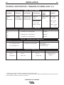
PRÉCAUTIONS DE SÛRETÉ
Pour votre propre protection lire et observer toutes les instructions
et les précautions de sûreté specifiques qui parraissent dans ce
manuel aussi bien que les précautions de sûreté générales suiv-
antes:
Sûreté Pour Soudage A L’Arc
1. Protegez-vous contre la secousse électrique:
a. Les circuits à l’électrode et à la piéce sont sous tension
quand la machine à souder est en marche. Eviter toujours
tout contact entre les parties sous tension et la peau nue
ou les vétements mouillés. Porter des gants secs et sans
trous pour isoler les mains.
b. Faire trés attention de bien s’isoler de la masse quand on
soude dans des endroits humides, ou sur un plancher met-
allique ou des grilles metalliques, principalement dans
les positions assis ou couché pour lesquelles une grande
partie du corps peut être en contact avec la masse.
c. Maintenir le porte-électrode, la pince de masse, le câble de
soudage et la machine à souder en bon et sûr état defonc-
tionnement.
d.Ne jamais plonger le porte-électrode dans l’eau pour le
refroidir.
e. Ne jamais toucher simultanément les parties sous tension
des porte-électrodes connectés à deux machines à souder
parce que la tension entre les deux pinces peut être le total
de la tension à vide des deux machines.
f. Si on utilise la machine à souder comme une source de
courant pour soudage semi-automatique, ces precautions
pour le porte-électrode s’applicuent aussi au pistolet de
soudage.
2. Dans le cas de travail au dessus du niveau du sol, se protéger
contre les chutes dans le cas ou on recoit un choc. Ne jamais
enrouler le câble-électrode autour de n’importe quelle partie du
corps.
3. Un coup d’arc peut être plus sévère qu’un coup de soliel, donc:
a. Utiliser un bon masque avec un verre filtrant approprié ainsi
qu’un verre blanc afin de se protéger les yeux du rayon-
nement de l’arc et des projections quand on soude ou
quand on regarde l’arc.
b. Porter des vêtements convenables afin de protéger la peau
de soudeur et des aides contre le rayonnement de l‘arc.
c. Protéger l’autre personnel travaillant à proximité au
soudage à l’aide d’écrans appropriés et non-inflammables.
4. Des gouttes de laitier en fusion sont émises de l’arc de
soudage. Se protéger avec des vêtements de protection libres
de l’huile, tels que les gants en cuir, chemise épaisse, pan-
talons sans revers, et chaussures montantes.
5. Toujours porter des lunettes de sécurité dans la zone de
soudage. Utiliser des lunettes avec écrans lateraux dans les
zones où l’on pique le laitier.
6. Eloigner les matériaux inflammables ou les recouvrir afin de
prévenir tout risque d’incendie dû aux étincelles.
7. Quand on ne soude pas, poser la pince à une endroit isolé de
la masse. Un court-circuit accidental peut provoquer un
échauffement et un risque d’incendie.
8. S’assurer que la masse est connectée le plus prés possible de
la zone de travail qu’il est pratique de le faire. Si on place la
masse sur la charpente de la construction ou d’autres endroits
éloignés de la zone de travail, on augmente le risque de voir
passer le courant de soudage par les chaines de levage,
câbles de grue, ou autres circuits. Cela peut provoquer des
risques d’incendie ou d’echauffement des chaines et des
câbles jusqu’à ce qu’ils se rompent.
9. Assurer une ventilation suffisante dans la zone de soudage.
Ceci est particuliérement important pour le soudage de tôles
galvanisées plombées, ou cadmiées ou tout autre métal qui
produit des fumeés toxiques.
10. Ne pas souder en présence de vapeurs de chlore provenant
d’opérations de dégraissage, nettoyage ou pistolage. La
chaleur ou les rayons de l’arc peuvent réagir avec les vapeurs
du solvant pour produire du phosgéne (gas fortement toxique)
ou autres produits irritants.
11. Pour obtenir de plus amples renseignements sur la sûreté, voir
le code “Code for safety in welding and cutting” CSA Standard
W 117.2-1974.
PRÉCAUTIONS DE SÛRETÉ POUR
LES MACHINES À SOUDER À
TRANSFORMATEUR ET À
REDRESSEUR
1. Relier à la terre le chassis du poste conformement au code de
l’électricité et aux recommendations du fabricant. Le dispositif
de montage ou la piece à souder doit être branché à une
bonne mise à la terre.
2. Autant que possible, I’installation et l’entretien du poste seront
effectués par un électricien qualifié.
3. Avant de faires des travaux à l’interieur de poste, la debranch-
er à l’interrupteur à la boite de fusibles.
4. Garder tous les couvercles et dispositifs de sûreté à leur place.
Mar. ‘93

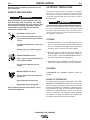
Thank You
for selecting a QUALITY product by Lincoln Electric. We want you
to take pride in operating this Lincoln Electric Company product •••
as much pride as we have in bringing this product to you!
Read this Operators Manual completely before attempting to use this equipment. Save this manual and keep it
handy for quick reference. Pay particular attention to the safety instructions we have provided for your protection.
The level of seriousness to be applied to each is explained below:
WARNING
This statement appears where the information must be followed exactly to avoid serious personal injury or
loss of life.
This statement appears where the information must be followed to avoid minor personal injury or damage to
this equipment.
CAUTION
Please Examine Carton and Equipment For Damage Immediately
When this equipment is shipped, title passes to the purchaser upon receipt by the carrier. Consequently, Claims
for material damaged in shipment must be made by the purchaser against the transportation company at the
time the shipment is received.
Please record your equipment identification information below for future reference. This information can be found
on your machine nameplate.
Model Name & Number _____________________________________
Code & Serial Number _____________________________________
Date of Purchase _____________________________________
Whenever you request replacement parts for or information on this equipment always supply the information you
have recorded above.
vv

TABLE OF CONTENTS
Page
Safety .........................................................................................................................i-iv
Installation .......................................................................................................Section A
Technical Specifications ........................................................................................A-1
Safety Precautions ................................................................................................A-2
Location/ Ventilation ..............................................................................................A-2
Storing.............................................................................................................A-2
Stacking ..........................................................................................................A-2
Angle of Operation ..........................................................................................A-2
Lifting...............................................................................................................A-3
High Altitude Operation ...................................................................................A-3
High Temperature Operation...........................................................................A-3
Towing .............................................................................................................A-3
Pre-Operation Engine Service...............................................................................A-4
Oil....................................................................................................................A-4
Fuel .................................................................................................................A-4
Fuel Cap..........................................................................................................A-4
Engine Coolant................................................................................................A-4
Battery Connection ..................................................................................A-4, A-5
Muffler Outlet Pipe ..........................................................................................A-5
Spark Arrestor .................................................................................................A-5
Radiator Cap Cover ........................................................................................A-5
Air Cleaner Inlet Hood.....................................................................................A-5
High Frequency Generators for TIG Applications .................................................A-5
Remote Control .....................................................................................................A-5
Welding Terminals .................................................................................................A-5
Welding Output Cables ...................................................................................A-6
Machine Grounding ...............................................................................................A-6
Auxiliary Power Receptacles.................................................................................A-6
Standby Power Connections...........................................................................A-6,A-7
Connection of Lincoln Electric Wire Feeders..................................................A-8,A-9
Operation .........................................................................................................Section B
Safety Instructions .................................................................................................B-1
General Description...............................................................................................B-1
Recommended Applications............................................................................B-1
Design Features and Advantages...................................................................B-1
Welding Capability ..........................................................................................B-2
Controls and Settings ............................................................................................B-3
Engine Controls ........................................................................................B-3,A-4
Welder Controls ..............................................................................................B-5
Auxiliary Power Controls.................................................................................B-5
Engine Operation...................................................................................................B-6
Starting the Engine .........................................................................................B-6
Stopping the Engine........................................................................................B-6
Break-In Period ...............................................................................................B-7
Typical Fuel Consumption...............................................................................B-7
Welder Operation ..................................................................................................B-7
Stick Welding ..................................................................................................B-7
TIG Welding..............................................................................................B-7,B-8
Wire Feed (Constant Voltage) Welding...........................................................B-9
Auxiliary Power Operation.....................................................................................B-9
Simultaneous Welding and Auxiliary Power Loads.........................................B-9
Arc Gouging ....................................................................................................B-9
Paralleling .......................................................................................................B-9
Extension Cord Length Recommendations.........................................................B-10
vivi
COMMANDER 500 CUMMINS

TABLE OF CONTENTS
Accessories.....................................................................................................Section C
Optional Field Installed Accessories .....................................................................C-1
Recommended Optional Equipment .....................................................................C-2
High Frequency Generators For TIG Applications ................................................C-2
Maintenance ....................................................................................................Section D
Safety Precautions ................................................................................................D-1
Routine and Periodic Maintenance .......................................................................D-1
Engine Maintenance..............................................................................................D-1
Air Filter...........................................................................................................D-1
Fuel Filters ......................................................................................................D-2
Cooling System...............................................................................................D-2
Battery Handling .....................................................................................D-2, D-3
Nameplate / Warning Decal Maintenance.............................................................D-3
Welder / Generator Maintenance ..........................................................................D-3
Engine Maintenance Components ........................................................................D-3
Troubleshooting ..............................................................................................Section E
Wiring,Connection Diagrams and Dimension Print.....................................Section F
Parts Lists ........................................................................................................P391Series
viivii
COMMANDER 500 CUMMINS

A-1
INSTALLATION
COMMANDER 500 CUMMINS
A-1
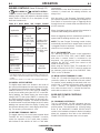
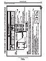
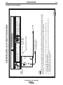
TECHNICAL SPECIFICATIONS -
COMMANDER 500 CUMMINS (K1846-1 & -2)
Make/Model Description Speed (RPM) Displacement Starting Capacities
System
Cummins 4 cylinder High Idle 1900 199 cu. in 12VDC battery Fuel: 25 gal.
B3.3 56 HP(42kw) Low Idle 1475 (3.3 L) & Starter 94.6 L
Diesel Engine @ 1800 RPM Full Load 1800
Bore x Stroke Oil: 8.0 Qts.
7.5L
3.74” x 4.53”
(95mm x 115mm) Coolant: 2.6 Gal.
11.8 L
INPUT - DIESEL ENGINE
RATED OUTPUT - WELDER
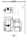
HEIGHT
2
WIDTH DEPTH WEIGHT
42.0 in. 31.5 in. 63.1 in. 1625 lbs.(737 kg)
( Approx.)
1066.8 mm 800.1 mm 1602.7 mm
OUTPUT - WELDER AND GENERATOR
Duty Cycle Welding Output Volts at Rated Amps
100%
500 Amps (DC multi-purpose) 40 Volts
60%
550 Amps (DC multi-purpose) 36 Volts
50%
575 Amps (DC multi-purpose) 35 Volts
Welding Range Open Circuit Voltage Auxiliary Power
1
30 - 575 Amps CC/CV 80 Max OCV @1900 RPM 120/240 VAC
12,000 Watts, 60 Hz.
20 - 250 Amps TIG 100% Duty Cycle
PHYSICAL DIMENSIONS
1. Output rating in watts is equivalent to volt-amperes at unity power factor.
Output voltage is within +/- 10% at all loads up to rated capacity. When welding, available auxiliary power will be reduced.
2. Top of Enclosure. Add 8.8” (223.5mm) for exhaust.

A-2
INSTALLATION
COMMANDER 500 CUMMINS
A-2
Read this entire installation section before you
start installation.
SAFETY PRECAUTIONS
Do not attempt to use this equipment until you
have thoroughly read all operating and mainte-
nance manuals supplied with your machine. They
include important safety precautions, detailed
engine starting, operating and maintenance
instructions and parts lists.
ELECTRIC SHOCK can kill.
•Do not touch electrically live parts
such as output terminals or internal
wiring.
•Insulate yourself from the work and
ground.
•Always wear dry insulating gloves.
------------------------------------------------------------------------
ENGINE EXHAUST can kill.
•Use in open, well ventilated areas or
vent exhaust outside
•Do not stack anything near the
engine.
------------------------------------------------------------------------
MOVING PARTS can injure.
•Do not operate with doors open or
guards off.
•Stop engine before servicing.
•Keep away from moving parts
------------------------------------------------------------------------
Only qualified personnel should install, use or
service this equipment.
LOCATION / VENTILATION
The welder should be located to provide an unrestricted
flow of clean, cool air to the cooling air inlets and to avoid
restricting the cooling air outlets. Also, locate the welder
so that the engine exhaust fumes are properly vented to
an outside area.
DO NOT MOUNT OVER COMBUSTIBLE SURFACES
Where there is a combustible surface directly under sta-
tionary or fixed electrical equipment, that surface should
be covered with a steel plate at least .06”(1.6mm) thick,
which should extend not less than 5.90(150mm) beyond
the equipment on all sides.
STORING
1. Store the machine in a cool, dry place when it is not
in use. Protect it from dust and dirt. Keep it where it
can’t be accidentally damaged from construction
activities, moving vehicles, and other hazards.
2. Drain the engine oil and refill with fresh 10W30 oil.
Run the engine for about five minutes to circulate oil
to all the parts. See the MAINTENANCE section of
this manual for details on changing oil.
3. Remove the battery, recharge it, and adjust the elec-
trolyte level. Store the battery in a dry, dark place.
STACKING
COMMANDER 500 CUMMINS machines cannot be
stacked.
ANGLE OF OPERATION
To achieve optimum engine performance the COM-
MANDER 500 CUMMINS should be run in a level posi-
tion. The maximum angle of operation for the Cummins
engine is 35 degrees in all directions. If the engine is to
be operated at an angle, provisions must be made for
checking and maintaining the oil level at the normal
(FULL) oil capacity in the crankcase. When operating
the welder at an angle, the effective fuel capacity will
be slightly less than the specified 25 gallons.
WARNING
CAUTION

A-3
INSTALLATION
COMMANDER 500 CUMMINS
A-3
LIFTING
The Commander lift bale should be used to lift the
machine. The Commander is shipped with the lift bale
retracted. Before attempting to lift the Commander the
lift bale must be secured in a raised position. Secure
the lift bale as follows:
a. Open the engine compartment door.
b. Locate the 2 access holes on the upper middle
region of compartment wall just below the lift
bale.
c. Use the lifting strap to raise the lift bale to the full
upright position. This will align the mounting
holes on the lift bale with the access holes.
d. Secure the lift bale with 2 thread forming screws.
The screws are provided in the shipped loose
parts bag.
FALLING EQUIPMENT can cause
injury.
• Do not lift this machine using lift
bale if it is equipped with a heavy
accessory such as a trailer or gas
cylinder.
• Lift only with equipment of ade-
quate lifting capacity.
• Be sure machine is stable when lift-
ing.
------------------------------------------------------------------------
HIGH ALTITUDE OPERATION
At higher altitudes, output derating may be necessary.
For maximum rating, derate the welder output 4% for
every 300 meters (984 ft.) above 1500 meters (4920
ft.). For output of 500A and below, derate the welder
output 4% for every 300 meters (984 ft.) above 2100
meters (6888 ft.).
Contact a Cummins Service Representative for any
engine adjustments that may be required.
HIGH TEMPERATURE OPERATION
At temperatures above 40°C (104°F), output voltage
derating may be necessary. For maximum output cur-
rent ratings, derate welder voltage rating 2 volts for
every 10°C (21°F) above 40°C (104°F).
TOWING
The recommended trailer for use with this equipment
for road, in-plant and yard towing by a vehicle
(1)
is
Lincoln’s K953-1. If the user adapts a non-Lincoln trail-
er, he must assume responsibility that the method of
attachment and usage does not result in a safety haz-
ard nor damage the welding equipment. Some of the
factors to be considered are as follows:
1. Design capacity of trailer vs. weight of Lincoln
equipment and likely additional attachments.
2. Proper support of, and attachment to, the base of
the welding equipment so that there will be no
undue stress to the trailer’s framework.
3. Proper placement of the equipment on the trailer to
insure stability side to side and front to back when
being moved and when standing by itself.
4. Typical conditions of use, such as travel speed,
roughness of surface on which the trailer will be
operated, and environmental conditions.
5. Proper preventative maintenance of trailer.
6. Conformance with federal, state and local laws
(1)
.
(1)
Consult applicable federal, state and local laws
regarding specific requirements for use on public high-
ways.
WARNING

A-4
INSTALLATION
COMMANDER 500 CUMMINS
A-4
PRE-OPERATION ENGINE SERVICE
READ the engine operating and maintenance instruc-
tions supplied with this machine.
•Keep hands away from the engine
muffler or HOT engine parts.
•Stop engine and allow to cool before
fueling.
• Do not smoke when fueling.
• Fill fuel tank at a moderate rate and do not over-
fill.
• Wipe up spilled fuel and allow fumes to clear
before starting engine.
• Keep sparks and flame away from tank.
------------------------------------------------------------------------
OIL
The Commander is shipped with the engine crankcase
filled with high quality SAE 10W-30 oil (API class CD or
better). Check the oil level before starting the engine. If it
is not up to the full mark on the dip stick, add oil as
required. Check the oil level every four hours of running
time during the first 35 running hours. Refer to the engine
Operator’s Manual for specific oil recommendations and
break-in information. The oil change interval is dependent
on the quality of the oil and the operating environment.
Refer to the engine Operator’s Manual for the proper ser-
vice and maintenance intervals.
FUEL USE DIESEL FUEL ONLY
Fill the fuel tank with clean, fresh diesel fuel. The capaci-
ty of the fuel tank is 25 gallons (94.6 liters). See engine
Operator’s Manual for specific fuel recommendations.
Running out of fuel may require bleeding the fuel
injection pump.
NOTE:
Before starting the engine, open the fuel shutoff
valve (pointer to be in line with hose).
FUEL CAP
Remove the plastic cap covering from the Fuel Tank
Filler neck and install the Fuel Cap.
ENGINE COOLANT
HOT COOLANT can burn skin.
• Do not remove cap if radiator is hot.
The welder is shipped with the engine and radiator
filled with a 50% mixture of ethylene glycol and water.
See the MAINTENANCE section and the engine
Operator’s Manual for more information on coolant.
BATTERY CONNECTION
GASES FROM BATTERY can explode.
• Keep sparks, flame and cigarettes
away from battery.
To prevent EXPLOSION when:
• INSTALLING A NEW BATTERY — disconnect
negative cable from old battery first and connect
to new battery last.
• CONNECTING A BATTERY CHARGER — remove
battery from welder by disconnecting negative
cable first, then positive cable and battery
clamp. When reinstalling, connect
negative cable last. Keep well ventilated.
• USING A BOOSTER — connect positive lead to
battery first then connect negative lead to nega-
tive battery lead at engine foot.
BATTERY ACID can burn eyes and
skin.
• Wear gloves and eye protection and
be careful when working near bat-
tery.
• Follow instructions printed on battery.
------------------------------------------------------------------------
IMPORTANT: To prevent ELECTRICAL DAMAGE
WHEN:
a) Installing new batteries.
b) Using a booster.
Use correct polarity — Negative Ground.
WARNING
WARNING
WARNING

A-5
INSTALLATION
COMMANDER 500 CUMMINS
A-5
The Commander is shipped with the negative battery
cable disconnected. Before you operate the machine,
make sure the Engine Switch is in the OFF position
and attach the disconnected cable securely to the neg-
ative (-) battery terminal.
Remove the insulating cap from the negative battery
terminal. Replace and tighten negative battery cable
terminal. NOTE: This machine is furnished with a wet
charged battery; if unused for several months, the bat-
tery may require a booster charge. Be sure to use the
correct polarity when charging the battery.
MUFFLER OUTLET PIPE
Remove the plastic plug covering the muffler outlet
tube. Using the clamp provided secure the outlet pipe
extension to the outlet tube. Install the rain cap on the
end of the outlet pipe extension.
SPARK ARRESTOR
Some federal, state or local laws may require that
gasoline or diesel engines be equipped with exhaust
spark arrestors when they are operated in certain loca-
tions where unarrested sparks may present a fire haz-
ard. The standard muffler included with this welder
does not qualify as a spark arrestor. When required by
local regulations, a suitable spark arrestor, must be
installed and properly maintained.
An incorrect arrestor may lead to damage to the
engine or adversely affect performance.
------------------------------------------------------------------------
RADIATOR CAP COVER
Install the radiator cap cover using the two screws
which are taped to the radiator cap cover.
AIR CLEANER INLET HOOD
Remove the plastic plug covering the air cleaner inlet.
Install the air cleaner inlet hood to the air cleaner.
HIGH FREQUENCY GENERATORS
FOR TIG APPLICATIONS
The K799 Hi-Freq Unit and the K930-1 or -2 TIG
Module are suitable for use with the COMMANDER
500 CUMMINS. The COMMANDER 500 CUMMINS is
equipped with the required R.F. bypass circuitry for the
connection of high frequency generating equipment.
The high frequency bypass network supplied with the
K799 Hi-Freq Unit does NOT need to be installed into
the COMMANDER 500 CUMMINS.
The COMMANDER 500 CUMMINS and any high fre-
quency generating equipment must be properly
grounded. See the K799 Hi-Freq Unit and the K930-1
or-2 TIG Module operating manuals for complete
instructions on installation, operation, and mainte-
nance.
REMOTE CONTROL
OUTPUT
The COMMANDER 500 CUMMINS is equipped with a
6-pin & 14-pin connector. The 6-pin connector is for
connecting the K857 or K857-1 Remote Control
(Optional) or in the case of TIG welding applications,
with the foot or hand Amptrol (K870 or K963-1 respec-
tively).
The 14-pin connector is used to directly connect a wire
feeder or TIG Module (K930-1 or -2) control cable.
NOTE: When using the 14-pin connector, if the wire
feeder has a built in power source output control, do
not connect anything to the 6-pin connector.
WELDING TERMINALS
The Commander is equipped with a toggle switch for
selecting "hot" welding terminals when in the "WELD
TERMINALS ON" position or "cold" welding terminals
when in the "REMOTELY CONTROLLED" position.
CAUTION

A-6
INSTALLATION
COMMANDER 500 CUMMINS
A-6
WELDING OUTPUT CABLES
With the engine off, route the electrode and work
cables thru the strain relief bracket provided on the
front of the base and connect to the terminals provid-
ed. These connections should be checked periodically
and tightened if necessary.
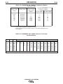
Listed in Table A.1 are copper cable sizes recom-
mended for the rated current and duty cycle. Lengths
stipulated are the distance from the welder to work and
back to the welder again. Cable sizes are increased for
greater lengths primarily for the purpose of minimizing
cable voltage drop.
Table A.1 Combined Length of Electrode and
Work Cables.
MACHINE GROUNDING
Because this portable engine driven welder creates its
own power, it is not necessary to connect its frame to
an earth ground, unless the machine is connected to
premises wiring (home, shop, etc.).
To prevent dangerous electric shock, other equipment
powered by this engine driven welder must:
a) be grounded to the frame of the welder using a
grounded type plug,
or
b) be double insulated.
When this welder is mounted on a truck or trailer, its
frame must be securely connected to the metal frame
of the vehicle. When this engine driven welder is con-
nected to premises wiring such as that in a home or
shop, its frame must be connected to the system earth
ground. See further connection instructions in the sec-
tion entitled “Standby Power Connections” as well as
the article on grounding in the latest U.S. National
Electrical Code and the local code.
In general, if the machine is to be grounded, it should
be connected with a #8 or larger copper wire to a solid
earth ground such as a metal water pipe going into the
ground for at least ten feet and having no insulated
joints, or to the metal framework of a building which
has been effectively grounded. The U.S. National
Electrical Code lists a number of alternate means of
grounding electrical equipment. A machine grounding
stud marked with the symbol is provided on the
front of the welder.
AUXILIARY POWER RECEPTACLES
The auxiliary power capacity of the COMMANDER 500
CUMMINS is 12,000 watts of 60 Hz, single phase
power. The auxiliary power capacity rating in watts is
equivalent to volt-amperes at unity power factor. The
maximum permissible current of the 240 VAC output is
50 A. The 240 VAC output can be split to provide two
separate 120 VAC outputs with a maximum permissi-
ble current of 50 A per output to two separate 120 VAC
branch circuits. The output voltage is within ± 10% at
all loads up to rated capacity.
NOTE:
The 120/240V receptacle has two 120V outlets
of different phases and cannot be paralleled.
The Commander has two 20 Amp-120VAC (5-20R)
duplex receptacles and one 50 Amp-120/240 VAC
(14-50R) receptacle. The 120/240 VAC receptacle can
be split for single phase 120 VAC operation. The aux-
iliary power receptacles should only be used with three
wire grounded type plugs or approved double insulat-
ed tools with two wire plugs. The current rating of any
plug used with the system must be at least equal to the
current capacity of the associated receptacle.
STANDBY POWER CONNECTIONS
The COMMANDER 500 CUMMINS is suitable for tem-
porary, standby or emergency power using the engine
manufacturer’s recommended maintenance schedule.
The COMMANDER 500 CUMMINS can be perma-
nently installed as a standby power unit for 240 volt-3
wire, 50 amp service. Connections must be made by a
licensed electrician who can determine how the
120/240 VAC power can be adapted to the particular
installation and comply with all applicable electrical
codes. The following information can be used as a
guide by the electrician for most applications. Refer to
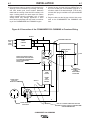
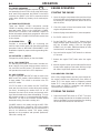
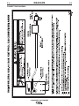
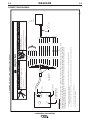
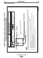
the connection diagram shown in Figure A.2.
1. Install the double-pole, double-throw switch
between the power company meter and the premis-
es disconnect.
Switch rating must be the same or greater than the
customer’s premises disconnect and service over cur-
rent protection.
Up to 150
FT.
3/0 AWG
150-200 FT.
3/0 AWG
200-250 FT.
4/0 AWG
AMPS
@100%
Duty Cycle
500
TOTAL COMBINED LENGTH OF ELEC-
TRODE AND WORK CABLES

A-7
INSTALLATION
COMMANDER 500 CUMMINS
A-7
2. Take necessary steps to assure load is limited to the
capacity of the Commander by installing a 50 amp,
240 VAC double pole circuit breaker. Maximum
rated load for each leg of the 240 VAC auxiliary is 50
amps. Loading above the rated output will reduce
output voltage below the allowable -10% of rated
voltage which may damage appliances or other
motor-driven equipment and may result in overheat-
ing of the COMMANDER 500 CUMMINS engine.
3. Install a 50 amp 120/240 VAC plug (NEMA Type 14-
50) to the double-pole circuit breaker using No. 6, 4
conductor cable of the desired length. (The 50 amp,
120/240 VAC plug is available in the optional K802R
plug kit.)
4. Plug this cable into the 50 Amp 120/240 Volt recep-
tacle on the COMMANDER 500 CUMMINS case
front.
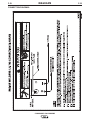
Figure A.2 Connection of the COMMANDER 500 CUMMINS to Premises Wiring
240 Volt
60 Hz.
3-Wire
Service
POWER
COMPANY
METER
240 VOLT
120 VOLT
120 VOLT
LOAD
N
NEUTRAL
BUS
GROUND
PREMISES
DISCONNECT AND
SERVICE
OVERCURRENT
PROTECTION
GND
N
NOTE: No. 6 COPPER CONDUCTOR CABLE SEE
NATIONAL ELECTRICAL CODE FOR ALTERNATE WIRE
SIZE RECOMMENDATIONS.
240 VOLT
GROUNDED CONDUCTOR
50AMP
240 VOLT
DOUBLE
POLE
CIRCUIT
BREAKER
DOUBLE POLE DOUBLE THROW
SWITCH RATING TO BE THE SAME
AS OR GREATER THAN PREMISES
SERVICE OVERCURRENT
PROTECTION.
50 AMP, 120/240
VOLT PLUG
NEMA TYPE 14-50
50 AMP, 120/240 VOLT
RECEPTACLE

A-8
INSTALLATION
COMMANDER 500 CUMMINS
A-8
CONNECTION OF LINCOLN
ELECTRIC WIRE FEEDERS
Shut off welder before making any electrical con-
nections.
------------------------------------------------------------------------
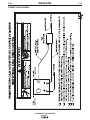
CONNECTION OF THE LN-25 TO THE
COMMANDER 500 CUMMINS
The LN-25 with or without an external contactor may
be used with the COMMANDER 500 CUMMINS. See
the appropriate connection diagram in the DIAGRAMS
section.
NOTE: The LN-25 (K431) Remote Control Module and
(K432) Remote Cable are not recommended for use
with the COMMANDER 500 CUMMINS.
• Shut the welder off.
• For electrode Positive, connect the electrode cable
from the LN-25 to the “+” terminal of the welder and
work cable to the “-” terminal of the welder. For elec-
trode Negative, connect the electrode cable from the
LN-25 to the “-” terminal of the welder and work
cable to the “+” terminal of the welder.
• Attach the single lead from the front of the LN-25 to
work using the spring clip at the end of the lead. This
is a sense lead to supply current to the wire feeder
motor; it does not carry welding current.
• Set the SELECTOR switch to the “CV-WIRE” posi-
tion.
• Set the “WELDING TERMINALS” switch to “WELD
TERMINALS ON”
• Adjust the “ARC CONTROL” knob to desired crisp-
ness. Generally, welding is best if the “ARC CON-
TROL” is set to SOFT for MIG and CRISP for
INNERSHIELD. You may however, want to start in
the middle and adjust (as needed) from there.
• Set the “IDLE” switch to the “AUTO” position. When
not welding, the COMMANDER 500 CUMMINS
engine will be at the low idle speed. If you are using
an LN-25 with an internal contactor, the electrode is
not energized until the gun trigger is closed.
If you are using an LN-25 without an internal con-
tactor, the electrode will be energized when the
COMMANDER 500 CUMMINS is started.
------------------------------------------------------------------------
h. When the gun trigger is closed, the current sensing
circuit will cause the COMMANDER 500 CUMMINS
engine to go to the high idle speed, the wire will
begin to feed and the welding process started.
When welding is stopped, the engine will revert to
low idle speed after approximately 12 seconds
unless welding is resumed.
CONNECTION OF LN-7 OR LN-8 TO THE
COMMANDER 500 CUMMINS
• Shut the welder off.
• Connect the LN-7 or LN-8 per instructions on the
appropriate connection diagram in the DIAGRAMS
section.
• Set the “WIRE FEEDER VOLTMETER” switch to
either “+” or “-” as required by the electrode being
used.
• Set the “SELECTOR” switch to the “CV-WIRE” posi-
tion.
• Adjust the “ARC CONTROL” knob to desired
Crispness. SOFT for MIG and CRISP for
INNERSHIELD.
• Set the “WELDING TERMINALS” switch to the
“REMOTELY CONTROLLED” position.
• Set the “IDLE” switch to the “HIGH” position. When
not welding, the COMMANDER 500 CUMMINS
engine will be at the low idle speed.
WARNING
CAUTION

A-9
INSTALLATION
COMMANDER 500 CUMMINS
A-9
CONNECTION OF AN LN-23P WIRE
FEEDER TO THE COMMANDER 500 CUM-
MINS
• Shut the welder off.
• Connect the LN-23P per instructions on the appro-
priate connection diagram in the DIAGRAMS sec-
tion. (NOTE): When connecting an LN-23P to the
COMMANDER 500 CUMMINS, a K350-1 adapter kit
must be used.
• Set the “WIRE FEEDER VOLTMETER” switch to “-”.
• Set the “SELECTOR” switch to “CV-WIRE” position.
• Set the “WELDING TERMINALS” switch to
“REMOTELY CONTROLLED”.
• Set the ARC CONTROL to desired crispness. SOFT
for MIG - CRISP for INNERSHIELD.
• Set the “IDLE” switch to the “HIGH” position. If you
are using an LN-23P with the K350-1 adapter kit, the
electrode is not energized until the gun trigger is
closed.
CONNECTION OF AN NA-3 AUTOMATIC
WELDING SYSTEM TO THE COMMANDER
500 CUMMINS
For connection diagrams and instructions for connect-
ing an NA-3 Welding System to the COMMANDER 500
CUMMINS, refer to the NA-3 Welding System instruc-
tion manual. The connection diagram for the LN-8 can
be used for connecting the NA-3.
CONNECTION OF AN LN-742 TO THE
COMMANDER 500 CUMMINS
• Shut the welder off.
• Connect the LN-742 per instructions on the appro-
priate connection diagram in the DIAGRAMS sec-
tion.
• Set the “WIRE FEEDER VOLTMETER” switch to
either “+” or “-” as required by the electrode being
used.
• Set the “SELECTOR” switch to the “CV-WIRE” posi-
tion.
• Adjust the “ARC CONTROL” knob to desired
Crispness. SOFT for MIG and CRISP for
INNERSHIELD.
• Set the “WELDING TERMINALS” switch to the
“REMOTELY CONTROLLED” position.
• Set the “IDLE” switch to the “AUTO” position. When
not welding, the COMMANDER 500 CUMMINS
engine will be at the low idle speed.

B-1
OPERATION
B-1
SAFETY INSTRUCTIONS
Read and understand this entire section before operat-
ing your COMMANDER 500 CUMMINS.
Do not attempt to use this equipment until you
have thoroughly read all operating and mainte-
nance manuals supplied with your machine. They
include important safety precautions, detailed
engine starting, operating and maintenance
instructions and parts lists.
ELECTRIC SHOCK can kill.
•Do not touch electrically live parts
such as output terminals or internal
wiring.
•Insulate yourself from the work and
ground.
•Always wear dry insulating gloves.
------------------------------------------------------------------------
ENGINE EXHAUST can kill.
•Use in open, well ventilated areas or
vent exhaust outside
•Do not stack anything near the
engine.
------------------------------------------------------------------------
MOVING PARTS can injure.
•Do not operate with doors open or
guards off.
•Stop engine before servicing.
•Keep away from moving parts
------------------------------------------------------------------------
Only qualified personnel should operate this
equipment.
ADDITIONAL SAFETY PRECAUTIONS
Always operate the welder with the hinged door
closed and the side panels in place as these pro-
vide maximum protection from moving parts and
insure proper cooling air flow.
GENERAL DESCRIPTION
The COMMANDER 500 CUMMINS is a diesel engine-
driven welding power source. The machine uses a
brush type alternating current generator for DC multi-
purpose welding and for 120/240 VAC auxiliary stand-
by power. The welding control system uses state of the
art Chopper T
echnology. The COMMANDER 500
CUMMINS is not recommended for pipe thawing.
The generator has a single sealed bearing for mainte-
nance free service. The rotor is a copper wound design
with two slip rings and brushes. The stator is wound
entirely with heavy gauge copper wire and insulated
with NEMA class F insulation material. The stator is
then impregnated with three layers of high quality var-
nish. After the stator is assembled using tie bars, the
entire assembly covered with an environmentally pro-
tective coating. These measures insure trouble-free
operation in the harshest environments.
The fuel tank is made from high density polyethylene
and holds 25 gallons of diesel fuel. This will provide
enough fuel to run for more than 12 hours at full load.
The Cummins B3.3 engine is equipped with a stan-
dard, heavy duty, combination fuel filter/water separa-
tor element.
RECOMMENDED APPLICATIONS
WELDER
The COMMANDER 500 CUMMINS provides excellent con-
stant current DC welding output for stick (SMAW) and TIG
welding. The COMMANDER 500 CUMMINS also provides
excellent constant voltage DC welding output for MIG
(GMAW) and Innershield (FCAW) welding.
GENERATOR
The COMMANDER 500 CUMMINS provides smooth
120/240 VAC output for auxiliary power and emergency
standby power.
DESIGN FEATURES AND ADVANTAGES
K1846-2 COMMANDER 500 CUMMINS Deluxe Model
Features For Welding:
• Excellent DC multi-purpose welding for stick, MIG, TIG, cored
wire and arc gouging applications.
• 30 to 500 amps output in five slope controlled ranges for out-
of position and pipe electrodes, one constant current output
range for general purpose welding, one constant voltage
range for MIG wire and cored wire welding and one 20-250
amp range for “Touch Start” TIG welding.
• 100% duty cycle at 500 amps output and 50% duty cycle at
575 amps output.
COMMANDER 500 CUMMINS
WARNING

B-2
OPERATION
B-2
FOR AUXILIARY POWER
• 12,000 watts of 120/240 VAC, 60Hz auxiliary power.
• Power for tools, 120/240 VAC lights, electric pumps
and for standby emergency power.
• Drive a 5 HP motor (provided it is started under no
load).
• Two 20 amp 120 VAC duplex receptacles for up to 40
amps of 120 VAC power.
• One 50 amp, 120/240 VAC dual voltage receptacle
for up to 50 amps of 240 VAC, and up to 50 amps per
side to separate branch circuits (not in parallel) of 120
VAC single phase auxiliary power. Allows easy con-
nection to premises wiring.
• Weld and AC auxiliary power at the same time (with-
in machine total capacity).
OTHER FEATURES
• Cummins 4-cylinder water cooled diesel engine.
Designed for long life, easy maintenance and excel-
lent fuel economy.
• Engine protection system shuts the engine down for
low oil pressure, high water temperature or a broken
fan/engine alternator belt.
• Gauges for oil pressure, oil temperature, engine alter-
nator output and fuel level (on K1846-2 only codes
above 10840 have a fuel level gauge on both K1846-
1 and K1846-2).
• Indicator lights for low oil pressure, high oil tempera-
ture and engine alternator low output/broken belt.
• Engine hour meter standard on all models.
• Extended range 25 gallon (94.6 l) fuel tank.
• Automatic idler reduces engine speed when not weld-
ing or drawing auxiliary power. This feature reduces
fuel consumption and extends engine life.
• Compact size fits crosswise in full size pick-up truck.
• Single side engine service.
• Copper alternator windings and high temperature
insulation for dependability and long life.
• New paint system on case and base for outstanding
corrosion protection.
K1846-1 COMMANDER 500 CUMMINS Standard
Model
The K1846-1 is the standard version of the
Commander 500, and has all the features of the
K1846-2 Deluxe version except there is no oil pressure
gauge, oil temperature gauge, engine alternator
gauge, nor dual output meters. This version does have
fully functional engine protection for low oil pressure,
high oil temperature, and alternator output with associ-
ated lights.
• A field installed Dual Output Meter and Gauge Kit
(K1768-2) is available for the K1846-1 Commander
500. The kit includes dual output meters, oil pressure
gauge, water temperature gage, and alternator
ammeter.
WELDING CAPABILITY
The COMMANDER 500 CUMMINS is rated at 500
amps, 40 VDC at 100% duty cycle and 575 amps, 36
VDC at 50% duty cycle. The maximum open circuit
voltage at 1900 RPM is 80 volts. The weld current is
variable from 30 to 575 amps.
COMMANDER 500 CUMMINS
• Dual 3-digit output meters are provided (optional on
K1846-1) for presetting the weld amperage or voltage
and displaying the actual amperage and voltage during
welding. The meters use superbrite L.E.D.'s for
improved readability in full sunlight.
LOOK-BACK FEATURE: After welding has stopped,
both displays will remain on for 7 seconds with the last
current and voltage value displayed. During this time,
the left-most decimal point in each display will be
FLASHING.
• Standard remote control capability with 14 pin and 6 pin
connectors for easy connection of Lincoln remote con-
trol accessories.
• An internal "Solid State" contactor allows for the selec-
tion of "hot" or "cold" output terminals with a toggle
switch on the control panel.
•“Arc Control”potentiometer in Wire and Stick modes for
precise adjustment of arc characteristics.
• Advanced circuitry to prevent pop-outs in the five slope
modes.

B-3
OPERATION
B-3
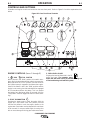
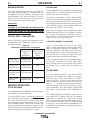
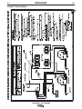
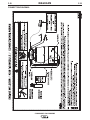
ENGINE CONTROLS (Items 1 through 8)
1. RUN STOP SWITCH
When placed in the “RUN” position, this switch ener-
gizes the fuel solenoid and other electric accessories.
When placed in the “STOP” position, the flow of fuel to
the injection pump is stopped to shut down the engine.
(Note: If the switch is left in the "RUN" position and the
engine is not running, the fuel solenoid will be engaged
for 15 seconds and then shut down. This is to protect
the battery from discharge. After 15 seconds, the Run
/ Stop switch must be toggled off then on before start-
ing.)
2. START PUSHBUTTON
Energizes the starter motor to crank the engine. With the
engine "Run / Stop" switch in the "Run" position, push and
hold the Start button to crank the engine; release as the
engine starts. Start button must be depressed for a minimum
of two seconds. Do not press while engine is running since
this can cause damage to the ring gear and/or starter motor.
3. FUEL LEVEL GAUGE
Displays the level of diesel fuel in the 25-
gallon fuel tank. The operator must
watch the fuel level closely to prevent running out
of fuel and having to bleed the system.
COMMANDER 500 CUMMINS
CONTROLS AND SETTINGS
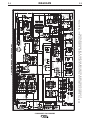
All welder and engine controls are located on the case front panel. Refer to Figure B.1 and the explanations that
follow.
Figure B.1 Case Front Panel Controls
1
2
3
4
5
6
7 8
9
19
12
17
18
14
16
20
9
FUEL
TEMP
WATER
PRESS
OIL
AMPS
10
11
15
13
La page charge ...
La page charge ...
La page charge ...
La page charge ...
La page charge ...
La page charge ...
La page charge ...
La page charge ...
La page charge ...
La page charge ...
La page charge ...
La page charge ...
La page charge ...
La page charge ...
La page charge ...
La page charge ...
La page charge ...
La page charge ...
La page charge ...
La page charge ...
La page charge ...
La page charge ...
La page charge ...
La page charge ...
La page charge ...
La page charge ...
La page charge ...
La page charge ...
La page charge ...
La page charge ...
La page charge ...
La page charge ...
La page charge ...
La page charge ...
-
 1
1
-
 2
2
-
 3
3
-
 4
4
-
 5
5
-
 6
6
-
 7
7
-
 8
8
-
 9
9
-
 10
10
-
 11
11
-
 12
12
-
 13
13
-
 14
14
-
 15
15
-
 16
16
-
 17
17
-
 18
18
-
 19
19
-
 20
20
-
 21
21
-
 22
22
-
 23
23
-
 24
24
-
 25
25
-
 26
26
-
 27
27
-
 28
28
-
 29
29
-
 30
30
-
 31
31
-
 32
32
-
 33
33
-
 34
34
-
 35
35
-
 36
36
-
 37
37
-
 38
38
-
 39
39
-
 40
40
-
 41
41
-
 42
42
-
 43
43
-
 44
44
-
 45
45
-
 46
46
-
 47
47
-
 48
48
-
 49
49
-
 50
50
-
 51
51
-
 52
52
-
 53
53
-
 54
54


Lincoln Electric Commander 500 Mode d'emploi
- Catégorie
- Système de soudage
- Taper
- Mode d'emploi
dans d''autres langues
Documents connexes
-
Lincoln Electric VANTAGE 575 Mode d'emploi
-
-
Lincoln Electric VANTAGE 500 Manuel utilisateur
-
-
-
-
-
-
-