Sauder Entertainment Credenza 412922 Mode d'emploi
- Taper
- Mode d'emploi

NOTE: THIS INSTRUCTION
BOOKLET CONTAINS IMPORTANT
SAFETY INFORMATION.
PLEASE READ AND KEEP FOR
FUTURE REFERENCE.
English pg 1-28
Français pg 29-32
Español pg 33-36
Lot # 372783 05/18/15
Purchased: __________________
Be sure to give us a ring before
making any returns. 1-800-523-3987
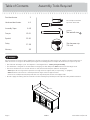
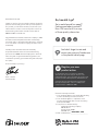
Entertainment Credenza
Carson Forge Collection | 412922
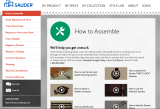
Need help? Visit Sauder.com to view video assembly tips or chat with a live rep.
Prefer the phone? Call 1-800-523-3987.
Share your journey!
sauder.com
It stands. You sit.
A thing of beauty,
this one.

Table of Contents Assembly Tools Required
3
4-5
6-28
29-32
33-36
37-38
39
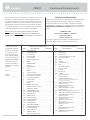
Part Identifi cation
Hardware Identifi cation
Assembly Steps
Français
Español
Safety
Warranty
Hammer
Not actual size
No. 2 Phillips Screwdriver
Tip Shown Actual Size
Use of a TV that is too heavy or large is hazardous. A TV that is too heavy will create a risk of a tip-over that can cause severe injury or
death. A TV that is too large for the available space might be accidentally pushed or bumped o the furniture, or subject to tip-over.
• Check the size and weight of your TV. Compare it to the diagram below – before you begin assembly!
• This Sauder unit is designed for use with televisions weighing less than 135 pounds. Never use with a TV that weighs more.
• The size of the television, front-to-back and side-to-side, must fi t within the space defi ned in the diagram.
• Never place the front edge of the TV past the front edge of the TV support shelf (or stop molding – if equipped)
• Never allow the sides of the TV to extend past the side edges of the TV support surface.
• If the TV has a CRT picture tube, the picture tube cone may extend past the rear of the support shelf.
• Be sure to apply the warning label as instructed in the last assembly step. The label provides important safety related information.
WARNING
!
135 lbs.
135 lbs.
15-1/2"
15-1/2"
60-3/4"
60-3/4"
Skip the power trip.
This time.
412922 www.sauder.com/servicesPage 2

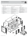
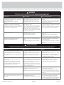
Part Identifi cation
å While not all parts are labeled, some of the parts will have a label or an inked letter on the edge
to help distinguish similar parts from each other. Use this part identifi cation to help identify similar parts.
A RIGHT END (1)
B LEFT END (1)
C RIGHT UPRIGHT (1)
D LEFT UPRIGHT (1)
E TOP (1)
F FLIP TOP (1)
G BOTTOM (1)
H SMALL BOTTOM (1)
I SHELF (1)
J SMALL BACK (1)
K DOOR (2)
L BACK (1)
M ADJUSTABLE SHELF (4)
N SMALL ADJUSTABLE SHELF (1)
O LEFT FRONT LEG (1)
P RIGHT FRONT LEG (1)
Q REAR LEG (2)
R DRAWER FRONT (1)
V SKIRT (1)
M75 END MOLDING (4)
X TOP MOLDING (1)
Y EXTENSION BLOCK (1)
D44 RIGHT DRAWER SIDE (1)
D45 LEFT DRAWER SIDE (1)
D62 DRAWER BACK (1)
D701 DRAWER BOTTOM (1)
Now you know
our ABCs.
412922www.sauder.com/services
Page 3
A
B
C
D
E
F
G
H
I
J
K
K
L
M
M
M
M
N
O
P
Q
R
V
M75
M75
M75
M75
X
Y
Q
D44
D45
D62
D701

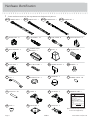
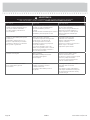
Hardware Identifi cation
å Screws are shown actual size. You may receive extra hardware with your unit.
FELT DISC CARD - 1
MM
METAL BRACKET - 2
HH
ANGLE BRACKET - 5
GG
GROMMET CAP - 2
QQ
RUBBER SLEEVE - 20
SS
METAL PIN - 20
TT
BUMPER - 4
OO
UU
HINGE - 4
VV
SW HINGE - 3
RR
GROMMET - 2
DRAWER FRONT
BRACKET - 1
II
PULL - 1
PP
NN
CORNER ACCENT - 2
FOOT - 4
JJ
CENTER FOOT - 1
KK
FOOT BASE - 1
LL
40CB
CABINET LEFT - 1
40CA
CABINET RIGHT - 1
40CC
DRAWER RIGHT - 1
40CD
DRAWER LEFT - 1
HIDDEN CAM - 31
1F
CAM DOWEL - 25
2F
CAM SCREW - 6
8F
CORD CLIP - 4
YY
KNOB - 2
WW
XX
BACKPLATE - 2
WARNING
Never use this furniture with a TV that is too
large or too heavy. Severe injury or death
can occur. The TV and furniture will be
unstable and may tip.
-The TV must less than 135 lbs.
-The base of the TV must be able to sit
completely on this shelf.
-Refer to instruction book for complete safety
information.
Note: This is a permanent label. Do not try
to remove. Surface will be damaged.
02/ 02 2 6 9 2 3 2 269232
WARNING LABEL - 1
ZZ
(Refer to the last step for proper
location and application)
412922 www.sauder.com/servicesPage 4

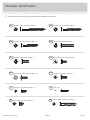
Hardware Identifi cation
å Screws are shown actual size. You may receive extra hardware with your unit.
412922www.sauder.com/services
Page 5
GGG
BLACK 9/16" LARGE HEAD SCREW - 18
EEE
SILVER 5/8" MACHINE SCREW - 2
BBB
BLACK 1-7/8" FLAT HEAD SCREW - 7
AAA
BLACK 2-1/4" FLAT HEAD SCREW - 6
DDD
BLACK 1-1/8" MACHINE SCREW - 2
HHH
SILVER 1/2" MACHINE SCREW - 2
LLL
NAIL - 60
JJJ
BLACK 1/2" FLAT HEAD SCREW - 14
FFF
BLACK 9/16" FLAT HEAD SCREW - 8
CCC
BROWN 1-5/8" FLAT HEAD SCREW - 4
GOLD 5/16" FLAT HEAD SCREW - 8
3S 30S
BLACK 1-9/16" FLAT HEAD SCREW - 4

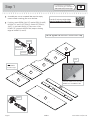
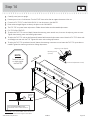
Step 1
Look for this icon. It means a
video assembly tip is available at
www.sauder.com/services/tips
å
Assemble your unit on a carpeted fl oor or on the empty
carton to avoid scratching your unit or the fl oor.
å
Push thirty-one HIDDEN CAMS (1F) into the ENDS (A and B),
UPRIGHTS (C and D), BOTTOM (G), SMALL BOTTOM (H),
SHELF (I), and SMALL BACK (J). Then, insert a CAM
DOWEL (2F) into each HIDDEN CAM, except in the long
edges of the ENDS (A and B).
412922 www.sauder.com/servicesPage 6
B
A
C
D
I
G
J
H
Arrow
1F
2F
Arrow
1F
2F
Insert the metal end of the CAM
DOWEL into the HIDDEN CAM.
Arrow
Do not tighten the HIDDEN CAMS in this step.
Do not insert
CAM DOWELS
into these edges.
(25 used)
(31 used)
Scan this QR code or go to this address:
http://qr.sauder.com/?ID=1128
to watch a video on how to assemble your unit.

å
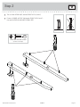
Turn six CAM SCREWS (8F) into the FRONT LEGS (O and P).
å
Fasten a CORNER ACCENT (NN) to each FRONT LEG (O and P).
Use two SILVER 5/8" MACHINE SCREWS (EEE).
Step 2
412922www.sauder.com/services
Page 7
P
O
NN
NN
8F
8F
SILVER 5/8" MACHINE SCREW
(2 used in this step)
EEE

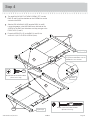
Step 3
å
Fasten the FRONT LEGS (O and P) to the ENDS (A and B).
Tighten six HIDDEN CAMS.
412922 www.sauder.com/servicesPage 8
A
B
O
P
Surface
with
HIDDEN
CAMS
1
2
Surface
without
HIDDEN
CAMS
Angled edge
Angled edge
Remember:
Righty tighty.
Lefty loosey.

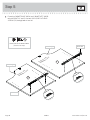
å
Turn eight BLACK 9/16" FLAT HEAD SCREWS (FFF) into the
ENDS (A and B) until the shoulders of the SCREWS rest on the
surfaces of the ENDS.
å
Slide the END MOLDINGS (M75) onto the ENDS (A and B).
Line up the grooves in the MOLDINGS over the heads of the
SCREWS in the ENDS and slide them until they are against the
FRONT LEGS (O and P).
å
Fasten the REAR LEGS (Q) to the ENDS (A and B). Use
six BLACK 2 1/4" FLAT HEAD SCREWS (AAA).
Step 4
412922www.sauder.com/services
Page 9
A
B
AAA
AAA
P
O
Q
Q
BLACK 9/16" FLAT HEAD SCREW
(8 used in this step)
FFF
BLACK 2-1/4" FLAT HEAD SCREW
(6 used in this step)
AAA
Angled edge
Angled edge
Apply pressure with your hands as
you guide the MOLDINGS over the
SCREWS and onto the END.
Shoulder
M75
M75
M75
M75
M75

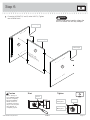
Step 5
å
Fasten the CABINET RIGHT (40CA) and CABINET LEFT (40CB)
to the UPRIGHTS (C and D). Use four GOLD 5/16" FLAT HEAD
SCREWS (3S) through holes #1 and #4.
412922 www.sauder.com/servicesPage 10
Surface with
HIDDEN CAM
Surface with
HIDDEN CAM
1
2
3
4
4
3
2
1
C
D
Curved edge
Curved edge
Roller end
Roller end
GOLD 5/16" FLAT HEAD SCREW
(4 used in this step)
3S

å
Fasten the UPRIGHTS (C and D) to the SHELF (I). Tighten
four HIDDEN CAMS.
Step 6
412922www.sauder.com/services
Page 11
Surface with
HIDDEN CAMS
C
D
I
Curved edge
Curved edge
Finished edge
Do not stand the unit upright without the
BACK fastened. The unit may collapse.
Caution
Start Tighten
Arrow
Minimum
190 degrees
Caution
Risk of damage or
injury. HIDDEN CAMS
must be completely
tightened. HIDDEN
CAMS that are not
completely tightened
may loosen, and parts
may separate. To
completely tighten:
Arrow
Maximum
210 degrees

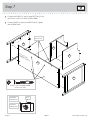
Step 7
å
Fasten the UPRIGHTS (C and D) to the BOTTOM (G). Use
four BLACK 1-7/8" FLAT HEAD SCREWS (BBB).
å
Fasten the ENDS (A and B) to the BOTTOM (G). Tighten
four HIDDEN CAMS.
412922 www.sauder.com/servicesPage 12
A
B
C
D
G
Arrow
Minimum
190 degrees
Maximum
210 degrees
BLACK 1-7/8" FLAT HEAD SCREW
(4 used in this step)
BBB
Surface with
HIDDEN CAMS
These holes
must be here.

å
Fasten the SMALL BACK (J) to the SMALL BOTTOM (H).
Use three 1-7/8" FLAT HEAD SCREWS (BBB).
å
Push the GROMMETS (RR) and GROMMET CAPS (QQ)
into the large holes in the SMALL BACK (J).
å
Fasten the SMALL BACK (J) and SMALL BOTTOM (H) to
the ENDS (A and B). Tighten four HIDDEN CAMS.
Step 8
412922www.sauder.com/services
Page 13
J
H
QQ
RR
BLACK 1-7/8" FLAT HEAD SCREW
(3 used in this step)
BBB
Edge with CAM DOWELS
Surface without
HIDDEN CAMS
Surface without
HIDDEN CAMS
A
B
H
Arrow
Minimum
190 degrees
Maximum
210 degrees
Surface with
HIDDEN
CAMS
J

å
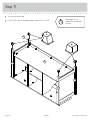
Push four CORD CLIPS (YY) into the holes in the TOP (E).
å
Fasten the TOP (E) to the ENDS (A and B) UPRIGHTS (C and D),
and SMALL BACK (J). Tighten nine HIDDEN CAMS.
412922 www.sauder.com/servicesPage 14
YY
E
A
B
C
D
Arrow
Minimum
190 degrees
Maximum
210 degrees
Step 9
J

Step 10
412922www.sauder.com/services
Page 15
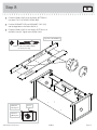
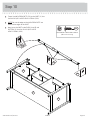
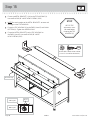
å
Fasten fi ve ANGLE BRACKETS (GG) to the SKIRT (V). Use
fi ve BLACK 9/16" LARGE HEAD SCREWS (GGG).
å
NOTE: Be sure the edges of the ANGLE BRACKETS are
even with the edges of the SKIRT.
å
Now, fasten the SKIRT to the ENDS (A and B) and
BOTTOM (G). Use fi ve BLACK 9/16" LARGE
HEAD SCREWS (GGG).
V
GG
GG
GG
A
B
G
BLACK 9/16" LARGE HEAD SCREW
(10 used in this step)
GGG

å
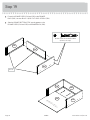
Turn your unit onto its top.
å
Push a FOOT (JJ) over the bottom edge of each LEG (O, P, and Q).
Step 11
412922 www.sauder.com/servicesPage 16
JJ
JJ
P
Q
Q
O
G
Don't worry. It isn't
Rome. This can be built
in a day.

Step 12
412922www.sauder.com/services
Page 17
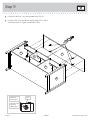
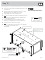
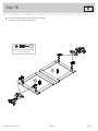
å
Carefully turn your unit over onto its front edges. Unfold the BACK (L) and
lay it over your unit.
å
Make equal margins along all the long edges of the BACK (L). Push on
opposite corners of your unit if needed to make it "square".
å
Fasten the BACK (L) to your unit using the NAILS (LLL).
å
NOTE: Be sure to tap NAILS into the holes that line up over the UPRIGHTS.
å
NOTE: Perforations have been provided for access through the BACK.
Carefully cut out the holes needed.
å
Fasten the EXTENSION BLOCK (Y) and FOOT BASE (LL) to the
BOTTOM (G). Use four BROWN 1-5/8" FLAT HEAD SCREWS (CCC).
å
Push the CENTER FOOT (KK) into the FOOT BASE.
å
NOTE: Turn the adjustable end of the ADJUSTABLE FOOT completely in.
Final adjustments will be made after the unit is
standing upright.
L
Y
KK
LL
Unfi nished
surface
G
Do not stand the unit upright without the
BACK fastened. The unit may collapse.
Caution
BROWN 1-5/8” FLAT HEAD SCREW
(4 used in this step)
CCC
These holes must be here.
These holes must line up over
the UPRIGHTS (C and D).
Turn completely in.
NAIL
(60 used for the BACK)
LLL

Step 13
412922 www.sauder.com/servicesPage 18
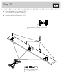
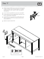
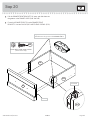
å
Fasten the SW HINGES (VV) to the FLIP TOP (F).
Use six BLACK 1/2" FLAT HEAD SCREWS (JJJ).
å
Push four BUMPERS (OO) into the FLIP TOP (F).
VV
VV
F
OO
SW is stamped into this HINGE for identifi cation.
BLACK 1/2" FLAT HEAD SCREW
(6 used in this step)
JJJ

å
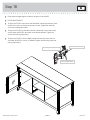
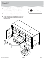
Carefully stand your unit upright.
å
Position your unit in its fi nal location. Turn the FOOT down to the fl oor to support the center of the unit.
å
Fasten the FLIP TOP (F) to the SMALL BACK (J). Use the screws in the HINGES.
å
Refer to the enlarged diagram to identify the parts on the SW HINGES.
å
The FLIP TOP may need some adjustments. Follow the text below to make needed adjustments.
å
FLIP TOP ADJUSTMENTS:
å
To adjust the FLIP TOP in or out (depth), loosen the mounting screw several turns, then turn the adjusting screw in or out.
Tighten the mounting screw after making adjustments.
å
To adjust the FLIP TOP side to side (horizontal), loosen both horizontal adjustment screws. Move the FLIP TOP side to side
so the edges are even with the TOP. Tighten the screws after making adjustments.
å
To adjust the FLIP TOP up or down (vertical), loosen the mounting screw one turn and move the FLIP TOP up or down as
needed. Tighten the mounting screw after making adjustments.
Step 14
412922www.sauder.com/services
Page 19
F
horizontal
vertical
depth
J
NOTE:
The FLIP-TOP will
sit slightly higher
than the TOP.
VV
Mounting screw
(vertical)
Adjusting screw (depth)
(horizontal adjustment screws)
Turn the ADJUSTABLE FOOT
downward until it touches the fl oor.
TT
Floor
IMPORTANT: The ADJUSTABLE FOOT should not
extend beyond the bottom edges of the LEGS.

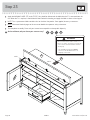
Step 15
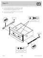
å
Fasten two METAL BRACKETS (HH) to the TOP MOLDING (X).
Use two BLACK 9/16" LARGE HEAD SCREWS (GGG).
å
NOTE: Be sure the edges of the METAL BRACKETS are even with
the edges of the TOP MOLDING.
å
Fasten the TOP MOLDING (X) to the ENDS (A and B) and SMALL
BOTTOM (H). Tighten four HIDDEN CAMS.
å
Fasten the METAL BRACKETS on the TOP MOLDING to
the ENDS (A and B). Use two BLACK 9/16" LARGE
HEAD SCREWS (GGG).
412922 www.sauder.com/servicesPage 20
HH
HH
X
X
A
B
H
Arrow
Minimum
190 degrees
Maximum
210 degrees
BLACK 9/16" LARGE HEAD SCREW
(4 used for the METAL BRACKETS)
GGG
Rounded edge
STOP
All FLIP-TOP
adjustments must
be made before
fastening the TOP
MOLDING (X).
La page est en cours de chargement...
La page est en cours de chargement...
La page est en cours de chargement...
La page est en cours de chargement...
La page est en cours de chargement...
La page est en cours de chargement...
La page est en cours de chargement...
La page est en cours de chargement...
La page est en cours de chargement...
La page est en cours de chargement...
La page est en cours de chargement...
La page est en cours de chargement...
La page est en cours de chargement...
La page est en cours de chargement...
La page est en cours de chargement...
La page est en cours de chargement...
La page est en cours de chargement...
La page est en cours de chargement...
La page est en cours de chargement...
La page est en cours de chargement...
-
 1
1
-
 2
2
-
 3
3
-
 4
4
-
 5
5
-
 6
6
-
 7
7
-
 8
8
-
 9
9
-
 10
10
-
 11
11
-
 12
12
-
 13
13
-
 14
14
-
 15
15
-
 16
16
-
 17
17
-
 18
18
-
 19
19
-
 20
20
-
 21
21
-
 22
22
-
 23
23
-
 24
24
-
 25
25
-
 26
26
-
 27
27
-
 28
28
-
 29
29
-
 30
30
-
 31
31
-
 32
32
-
 33
33
-
 34
34
-
 35
35
-
 36
36
-
 37
37
-
 38
38
-
 39
39
-
 40
40


Sauder Entertainment Credenza 412922 Mode d'emploi
- Taper
- Mode d'emploi
dans d''autres langues
Documents connexes
-
Sauder Storage Organizer 422647 Mode d'emploi
-
-
-
Unbranded 426152 Mode d'emploi
-
 Sauder Woodworking 420267 Manuel utilisateur
-
-
-
-
-