Thermador PALPKITGW Guide d'installation
- Catégorie
- Cuisinières
- Taper
- Guide d'installation
Ce manuel convient également à

THERMADOR.COM
Installation
INSTRUCTIONS
Pro Harmony
®
, Pro Grand
®
, and Pro Rangetop Propane (LP) Conversion Kit

THERMADOR.COM
Installation
INSTRUCTIONS
Table of contents (English) ................................................................ 3
Table de matières (Français)............................................................ 24
Índice de materias (Español)............................................................ 46
Models |
Modèles |
Modelos:
PALPKITHW
PALPKITHW5
PALPKITGW
PALPKITGW5
PALPKITDGW
PALPKITGGW
Pro Harmony
®
, Pro Grand
®
, and Pro Rangetop Propane (LP) Conversion Kit

Page. 3
This THERMADOR
®
appliance is made by
BSH Home Appliances Corporation
1901 Main Street, Suite 600
Irvine, CA 92614
Questions?
1-800-735-4328
www.thermador.com
We look forward to hearing from you!
Table of
CONTENTS
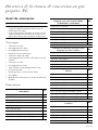
Safety ...................................................................................... 4
Important safety instructions .......................................... 4
Propane (LP) gas conversion instructions ............................... 6
Before you begin ............................................................ 6
Checklist.......................................................................... 7
Installation procedure............................................................. 9
Disassembling the rangetop........................................... 9
Converting the regulator to LP....................................... 10
Changing the STAR® burner orifices ............................. 10
Propane (LP) burner orifice conversion tables................ 12
Changing the broil orifice, on GAS ranges only............. 15
Changing the bake orifice, on GAS ranges only ............ 18
Checking for gas leaks.................................................... 19
Checking the flame and burner performance................. 20
Setting the STAR burner valve screws ............................ 22
Placing the conversion label ........................................... 23
Support, accessories, and parts..................................back page
Safety
DEFINITIONS
9 WARNING
This indicates that death or serious injuries may occur as a
result of non-observance of this warning.
9 CAUTION
This indicates that minor or moderate injuries may occur as a
result of non-observance of this warning.
NOTICE: This indicates that damage to the appliance or
property may occur as a result of non-compliance with this
advisory.
Note: This alerts you to important information and/or tips.

Page. 4
Safety
9 IMPORTANT SAFETY INSTRUCTIONS
READ AND SAVE THESE INSTRUCTIONS
Please read carefully
Save the original gas parts for possible conversion back in
the future.
Important: Only a qualified service technician or installer
should make this conversion.
Installer: Please leave these instructions with this unit for
the owner.
Owner: Please retain these instructions for future
reference.
This kit is for converting Thermador appliances for
operation with propane (LP) gas. This kit contains orifices
for proper LP conversion for oven bake, broiler, and top
surface STAR
®
burners.
This kit is used to convert select models of Pro Rangetop,
Pro Harmony, and Pro Grand ranges to propane (LP) gas
usage. This kit cannot be used to convert older models of
rangetops or ranges. This kit cannot be used to convert
any other brand of appliance.
WARNING
This conversion kit shall be installed by a
qualified service agency in accordance with the
manufacturer’s instructions and all applicable
codes and requirements of the authority having
jurisdiction. In any case, the installation of this
conversion kit must conform with local codes
or, in the absence of local codes, with the
National Fuel Gas Code, ANSI Z223.1/NFPA 54
or, in Canada, the Natural Gas and Propane
Installation Code, CSA B149, latest edition. If
the information in these instructions is not
followed exactly, a fire, explosion or
production of carbon monoxide may result
causing property damage, personal injury, or
loss of life. The qualified service agency is
responsible for the proper installation of this
kit. The installation is not proper and complete
until the operation of the converted appliance
is checked as specified in the manufacturer’s
instructions supplied with the kit.
WARNING
Never Operate the Top Surface Cooking Section of this
Appliance Unattended
• Failure to follow this warning statement could result
in fire, explosion, or burn hazard that could cause
property damage, personal injury, or death.
• If a fire should occur, keep away from the appliance
and immediately call your fire department. DO NOT
ATTEMPT TO EXTINGUISH AN OIL/GREASE FIRE
WITH WATER.
WARNING
If the information in this manual is
not followed exactly, a fire or
explosion may result causing
property damage, personal injury, or
death.
-- DO NOT store or use gasoline or other
flammable vapors and liquids in the
vicinity of this or any other appliance.
-- WHAT TO DO IF YOU SMELL GAS
• DO NOT try to light any appliance.
• DO NOT touch any electrical switch.
• DO NOT use any phone in your
building.
• Immediately call your gas supplier
from a neighbor’s phone. Follow the
gas supplier’s instructions.
• If you cannot reach your gas supplier,
call the fire department.
-- Installation and service must be
performed by a qualified installer, service
agency or the gas supplier.

Page. 5
9 IMPORTANT SAFETY INSTRUCTIONS
READ AND SAVE THESE INSTRUCTIONS
For Massachusetts installations
1. Installation must be performed by a qualified or
licensed contractor, plumber, or gas fitter qualified or
licensed by the state, province or region.
2. Shut-off valve must be a “T” handle gas cock.
3. Flexible gas connector must not be longer than 36
inches.
The following must be met when testing supply piping
system:
• The appliance and its individual shut-off valve must be
disconnected from the gas supply piping system at
test pressures in excess of 1/2 psig (3.5 kPa).
• The appliance must be isolated from the gas supply
piping system by closing its individual manual shut-off
valve during any pressure testing of the gas supply
piping system at test pressures equal to or less than
1/ 2 psig (3.5 kPa).
CAUTION
When connecting the unit to propane gas, make certain
the propane gas tank is equipped with its own high
pressure regulator. The maximum gas pressure to this
appliance is not to exceed 14.0 inches water column
(3.5 kPa) from the propane gas tank regulator.
The minimum propane (LP) gas supply pressure for the
checking of the gas appliance pressure regulator, when
converted for use with propane gas, must be between 11
inches water column (2.7 kPa) and 14 inches water column
(3.5 kPa). Please refer to page 10 on to how to properly
convert the gas pressure regulator for use with propane
(LP) gas.
WARNING
Never leave the gas conversion partially completed. If the
appliance is operated while the gas conversion is
incomplete, high levels of carbon monoxide may be
emitted, or a fire or explosion may occur, causing property
damage, personal injury, or death.
Save the original natural gas orifices removed from the
appliance for future use. Make sure that you carefully mark
and label these orifices, indicating the correspondent
burner from which they were removed.
To convert the appliance back for use with natural gas,
follow these instructions exactly, but replacing the
propane gas orifices with the original natural gas ones.
Carefully match their correspondent burners as previously
marked and labeled.
To the service agent
It is important that you know the following BEFORE you
begin the conversion of the appliance.
• Confirm that the gas supply system is available and
ready to use. This is particularly important for new
construction.
• Verify the type of gas supplied to the location. Ensure
that the appliance is connected to the type of gas for
which it is certified.
• You must plan for sufficient time and resources to
perform the conversion process properly and
completely before leaving the job site. Every step
described in these instructions must be performed to
safely convert the appliance for proper operation with
propane (LP) gas. INCOMPLETE OR INADEQUATE
CONVERSION OF THE APPLIANCE CAN CREATE A
SAFETY HAZARD.
Proposition 65 Warning
This product may contain a chemical known to the State of
California, which can cause cancer or reproductive harm.
Therefore, the packaging of your product may bear the
following label as required by California:
State of California Proposition 65 Warning:
: WARNING
Cancer and Reproductive Harm -
www.P65Warnings.ca.gov

Page. 6
Propane (LP) gas conversion instructions
Before you begin
9 CAUTION
Before proceeding with the conversion, shut off the
gas supply to the appliance prior to disconnecting the
electrical power.
Disconnect the appliance from electrical power by
unplugging the electrical cord from its receptacle or
by disconnecting power at the circuit breaker box.
Tools needed
• T-20 torx driver
• 7/16'' box end wrench
• 13/16'' box end wrench
• 7 mm or a 9/32'' socket
• 1/4'' nut driver
• 16 mm hex bit or 5/8'' hex bit or 16 mm Allen wrench
• T-30 torx driver
• 1/2'' offset box end wrench
• 9 mm Allen wrench or 9 mm hex bit
• 9/32'' open end wrench
• 7/8'' socket or 7/8'' open end wrench
• Adjustable wrench
• Soap and water mixture or leak-check solution
LP gas kit parts included
Gas Pro Harmony ranges with 5 burners
(PRG305WH)
Qty.
Conversion label 1
Foam tape, 1'' piece 1
Screwdriver, 1/8'' x 0.20'' 1
Orifice, 0.73 mm (73) 2
Orifice, 0.90 mm (90) 1
Orifice, 1.05 mm (105) 1
Orifice, 1.15 mm (115) 1
Orifice, 1.34 mm (134), main oven bake 1
Orifice, 1.25 mm (125), main oven broil 1
Dual Fuel Pro Harmony ranges and Pro
Rangetop with 5 burners
(PRD305WH(U/C) or PCG305W)
Qty.
Conversion label 1
Foam tape, 1'' piece 1
Screwdriver, 1/8'' x 0.20'' 1
Orifice, 0.73 mm (73) 2
Orifice, 0.90 mm (90) 1
Orifice, 1.05 mm (105) 1
Orifice, 1.15 mm (115) 1
Dual Fuel Pro Harmony ranges and Pro
Rangetop with 4 or 6 burners
Qty.
Conversion label 1
Foam tape, 1'' piece 1
Screwdriver, 1/8'' x 0.20'' 1
Orifice, 1.05 mm (105) 3
Orifice, 1.15 mm (115) 3
Gas Pro Harmony ranges with 4 or 6 burners Qty.
Conversion label 1
Foam tape, 1'' piece 1
Screwdriver, 1/8'' x 0.20'' 1
Orifice, 1.05 mm (105) 3
Orifice, 1.15 mm (115) 3
Orifice, 1.34 mm (134), main oven bake 1
Orifice, 1.13 mm (113), aux oven bake 1
Orifice, 1.25 mm (125), main oven broil 1
Orifice, 0.75 mm (75), aux oven broil 1
Dual Fuel Pro Grand ranges with 4 or 6
burners
Qty.
Conversion label 1
Foam tape, 1'' piece 1
Screwdriver, 1/8'' x 0.20'' 1
Orifice, 1.05 mm (105) 3
Orifice, 1.15 mm (115) 2
Orifice, 1.26 mm (126) 1

Page. 7
Checklist
Each of the following steps must be completed correctly
for the appliance to function properly. Check off each step
as it is finished.
Pro Rangetop models
Pro Harmony gas models
Pro Harmony dual fuel models
Gas Pro Grand ranges with 4 or 6 burners Qty.
Conversion label 1
Foam tape, 1'' piece 1
Screwdriver, 1/8'' x 0.20'' 1
Orifice, 1.05 mm (105) 3
Orifice, 1.15 mm (115) 2
Orifice, 1.26 mm (126) 1
Orifice, 1.46 mm (146), main oven bake 1
Orifice, 1.13 mm (113), aux oven bake 1
Orifice, 1.25 mm (125), main oven broil 1
Orifice, 0.813 mm (813) or “67”, aux oven broil* 1
*This orifice is stamped “67”, which means #67 DMS (Drill
Metal Standard, or wire gage number, or drill size) and is
dimensionally equal to 0.0320'' or 0.813 mm diameter.
Ù Step 1
Disassemble the rangetop (page 9).
Ù Step 2
Convert the regulator to LP gas (page 10).
Ù Step 3
Change the STAR® burner orifices according
to your model and the corresponding table
(page 10).
Ù Step 4
Check the rangetop for gas leaks (page 19).
Ù Step 5
Reassemble the rangetop and check STAR
burner flame performance (page 20).
Ù Step 6
Set the valve screws for the STAR burners
(page 22).
Ù Step 7
Place the conversion label (page 23).
Ù Step 1
Disassemble the rangetop (page 9).
Ù Step 2
Convert the regulator to LP gas (page 10).
Ù Step 3
Change the STAR burner orifices according
to your model and the corresponding table
(page 10).
Ù Step 4
Remove the backguard (page 15).
Ù Step 5
Change the main oven broil burner orifice to
the 1.25 mm (125) orifice (page 15).
Ù Step 6
48'' models – change the aux oven broil
burner orifice to the 0.75 mm (75) orifice
(page 15).
Ù Step 7
Remove the oven door(s) (page 16).
Ù Step 8
Remove the kick and front panels (page 17).
Ù Step 9
Change the main oven bake burner orifice to
the 1.34 mm (134) orifice (page 18).
Ù Step 10
48'' models – change the aux oven bake
burner orifice to the 0.75 mm (75) orifice
(page 18).
Ù Step 11
Reinstall the door(s) (page 17).
Ù Step 12
Check the rangetop and oven for gas leaks
(page 19).
Ù Step 13
Reassemble the rangetop and check STAR
burner flame performance (page 20).
Ù Step 14
Set the STAR burner valve screws (page 22).
Ù Step 15
Check the broil and bake burner flame
performance (page 22).
Ù Step 16
Reinstall the kick and front panels (page 17).
Ù Step 17
Place the conversion label (page 23).
Ù Step 1
Disassemble the rangetop (page 9).
Ù Step 2
Convert the regulator to LP gas (page 10).
Ù Step 3
Change the STAR burner orifices according
to your model and the corresponding table
(page 10).
Ù Step 4
Check the rangetop for gas leaks (page 19).
Ù Step 5
Reassemble the rangetop and check STAR
burner flame performance (page 20).
Ù Step 6
Set the valve screws for the STAR burners
(page 22).
Ù Step 7
Place the conversion label (page 23).

Page. 8
Pro Grand gas models Pro Grand dual fuel models
Ù Step 1
Disassemble the rangetop (page 9).
Ù Step 2
Convert the regulator to LP gas (page 10).
Ù Step 3
Change the STAR® burner orifices according
to your model and the corresponding table
(page 10).
Ù Step 4
Remove the backguard (page 15).
Ù Step 5
Change the main oven broil burner orifice to
the 1.25 mm (125) orifice (page 15).
Ù Step 6
48'' models – change the aux oven broil
burner orifice to the 0.813 mm (813) or #67
orifice (page 15).
Ù Step 7
Remove the oven door (page 16).
Ù Step 8
Remove the kick and front panels (page 17).
Ù Step 9
Change the main oven bake burner orifice to
the 1.46 mm (146) orifice (page 18).
Ù Step 10
48'' models – change the aux oven bake
burner orifice to the 1.13 mm (113) orifice
(page 18).
Ù Step 11
Reinstall the door(s) (page 17).
Ù Step 12
Check the rangetop and oven for gas leaks
(page 19).
Ù Step 13
Reassemble the rangetop and check STAR
burner flame performance (page 20).
Ù Step 14
Set the valve screws for the STAR burners
(page 22).
Ù Step 15
Check the broil and bake burner flame
performance (page 22).
Ù Step 16
Reinstall the kick and front panels (page 17).
Ù Step 17
Place the conversion label (page 23).
Ù Step 1
Disassemble the rangetop (page 9).
Ù Step 2
Convert the regulator to LP gas (page 10).
Ù Step 3
Change the burner orifices according to your
model and the corresponding table
(page 10).
Ù Step 4
Check the rangetop for gas leaks (page 19).
Ù Step 5
Reassemble the rangetop and check STAR
burner flame performance (page 20).
Ù Step 6
Set the valve screws for the STAR burners
(page 22).
Ù Step 7
Place the conversion label (page 23).

Page. 9
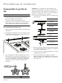
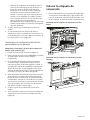
Installation procedure
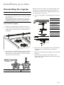
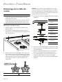
Disassembling the rangetop
9 CAUTION
Before proceeding with the conversion, shut off the
gas supply to the appliance prior to disconnecting the
electrical power.
Disconnect the appliance from electrical power by
unplugging the electrical cord from its receptacle or
by disconnecting power at the circuit breaker box.
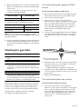
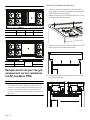
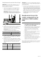
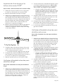
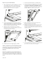
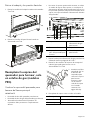
To disassemble the rangetop
1. Remove the rangetop grates and the burner caps.
2. To facilitate the removal of the spill tray, remove the T-
20 torx screws in the front face of the island trim or
backguard.
3. Use a 16 mm hex head bit or Allen wrench for burners
labeled ‘D’ or ‘F’. Use a 9 mm hex head bit or Allen
wrench for burners labeled ‘B’ to remove the burner
venturi from each burner base.
TIP: If a 16 mm hex head bit is not readily available, a 5/8''
hex bit can be selected. Alternatively, a bolt with 5/8''
head either “double-nutted” or tightened into the chuck
of a power driver can be used.
4. Disconnect the igniter. Carefully pull up on the burner
base.
5. Remove the screw securing the burner pedestal with a
T-30 torx driver. Carefully remove each burner
pedestal.
6. Remove the spill trays by pivoting the trays up and out
the back.
7. Remove the heat shield on some models. Some
models have a double-width shield that extends under
adjacent spill tray.
a. Hex head bit or Allen wrench b. Burner venturi
1
2
a
b
a. Grate
b. Burner cap
c. Venturi
d. Burner base
e. Electrode
f. Burner pedestal
g. Spill tray
h. Heat shield
i. Igniter housing
j. Igniter wire
d
b
a
e
f
g
h
c
i
j

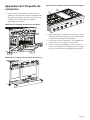
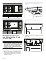
Page. 10
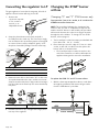
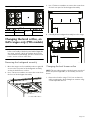
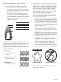
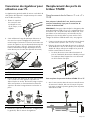
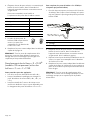
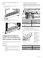
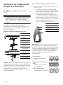
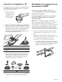
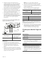
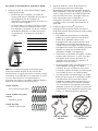
Converting the regulator to LP
The gas regulator is located in the rangetop, left side of
appliance. Exact location will vary per model.
2. Grasp the plastic button stem firmly and pull it
forcefully from the metal cap. The stem snaps snugly
into an indent in the cap and may require a strong pull
to remove. (Hint: it may be helpful to gently “rock”
the plastic stem while pulling it from the metal cap.)
3. Rotate the stem 180° so the letters “LP” on the stem
are upside down when the cap is set flat on its head.
Snap the stem back in place in this position inserting it
into the indent in the metal cap.The stem should snap
into place.
4. Reinstall conversion cap, configured for LP gas, back
into top of the regulator.
Changing the STAR
®
burner
orifices
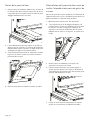
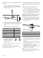
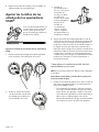
Changing “D” and “F” STAR burners only
To prepare the 7 mm, 9/32'' socket, or ¼'' nut driver for
STAR burner orifice conversion
NOTE: This procedure facilitates the changing of the
orifices in the “D” and “F” STAR burners only. For the
smaller sized “B” burners in 305 models, this procedure
will not work because the socket is too big for insertion
through the orifice holders. To change “B” size STAR
burners, refer to page 11.
1. Trim a small piece of the foam tape provided with this
kit to about 1/4 – 1/2'' (6 – 12 mm).
2. Place foam tape over the edge of a 7 mm or a 9/32''
socket, or with 1/4'' nut driver used to replace the
burner orifices, as shown below.
• The foam tape helps to retain the orifice in the
end of the nut driver so it will not fall inside the
appliance during orifice removal or installation.
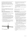
To replace the STAR “D” and “F” burner orifices
1. With the foam tape wrapped nut driver, reach down
through the jet holders and remove the gas orifice
from the STAR burner’s jet holder.
1. Remove the
conversion cap with
a 7/8'' socket or
wrench, or an
adjustable wrench.
a. Spring
b. Plastic button stem
c. Gasket
a. Natural gas b. LP gas
a
b
c
a
b
1
2

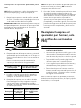
Page. 11
2. Label each of the removed orifices, noting from which
burner they were removed, in the event the appliance
is converted back to natural gas in the future.
For your convenience, note the orifice sizes and
locations in the following table.
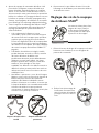
3. Locate the proper STAR
®
burner
orifices included with the kit.
Orifices are stamped with the
orifice diameter size on the side.
4. Replace orifices as indicated in the tables beginning
on page 12. Ensure the orifice is completely seated
and tight to the jet holder to avoid possible gas leaks.
NOTE: All of the replacement orifices in the conversion kit
have straight threads (not pipe threads) and do not
require thread sealing compound.
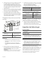
Changing “B” STAR burners (305 models
only) and/or “D” and “F” STAR burners
This procedure can be applied when:
• Converting size “B” burners.
• Preferred by the installer to change orifices of any size
burner (“B”, “D”, or “F”).
• A 7 mm or 9/32'' socket, or ¼'' nut driver is not
available for use when changing the orifices on “D”
and “F” burners.
To replace the “B” STAR burner orifices (or any burner
size orifice)
1. From the side of the jet holder, insert a 9/32'' open
end wrench into the space between the metal wire
and the jet holder. Remove the gas orifice from the
STAR burner’s jet holder.
2. Label each of the removed orifices, noting from which
burner they were removed, in the event the appliance
is converted back to natural gas in the future. (See
table to the left.)
3. Locate the proper STAR burner
orifices included with the kit.
Orifices are stamped with the
orifice diameter size on the side.
4. Replace orifices as indicated in the tables beginning
on page 12. Ensure the orifice is completely seated
and tight to the jet holder to avoid possible gas leaks.
NOTE: All the replacement orifices in the conversion kit
have straight threads (not pipe threads) and do not
require thread sealing compound.
Burner location Orifice size
Left front
Left rear
Center front
Center rear
Right front
Right rear
a. Jet holder
b. Metal wire
c. Gas orifice
a
b
c

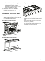
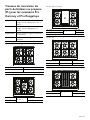
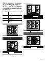
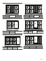
Page. 12
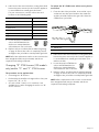
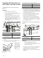
Pro Harmony ranges and Pro
Rangetops propane (LP)
burner orifice conversion kits
PALPKITHW For Pro Harmony dual fuel ranges and
Pro Rangetops with 4 and 6 burners
PALPKITHW5 For Pro Harmony dual fuel ranges and
Pro Rangetops with 5 burners
PALPKITGW For Pro Harmony gas ranges with 4 and
6 burners
PALPKITGW5 For Pro Harmony gas ranges with 5
burners
Model 304
(1)105 (3)105
(2)115 (4)115
Model 305
(1) 73
(3) 90
(4) 73
(2)115 (5)105
44
11
22
33
33
55
11
22
44
Model 364 with griddle
(1) 105
(3) —
(4) 105
(2) 115 (5) 115
Model 366
(1) 105 (3) 105 (5) 105
(2) 115 (4) 115 (6) 115
Model 364 with grill
(1) 105
(3) —
(4) 105
(2) 115 (5) 115
33
55
11
22
44
33
44
66
11
22
55
33
55
11
22
44

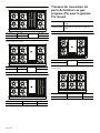
Page. 13
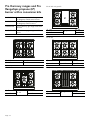
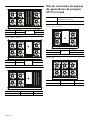
Pro Grand propane (LP) burner
orifice conversion kits
Model 486 with grill
(1) 105 (3) 105
(5) —
(6) 105
(2) 115 (4) 115 (7) 115
Model 486 with griddle
(1) 105 (3) 105
(5) —
(6) 105
(2) 115 (4) 115 (7) 115
Model 486 with griddle and grill
(1) 105 (3) 105 (5) —
(2) 115 (4) 115 (6) —
33
44
77
11
22
66
55
33
44
77
11
22
66
55
33
44
11
22
55
66
PALPKITDGW For all Pro Grand dual fuel ranges
PALPKITGGW For all Pro Grand gas ranges
Model 364 with griddle
(1) 105
(3) —
(4) 105
(2) 126 (5) 115
Model 366
(1) 105 (3) 105 (5) 105
(2) 126 (4) 115 (6) 115
Model 364 with grill
(1) 105
(3) —
(4) 105
(2) 126 (5) 115
33
55
11
22
44
33
44
66
11
22
55
33
55
11
22
44

Page. 14
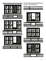
Model 364 with induction
(1)105 (3)105
(5) —
(2)126 (4)115
Model 486 with induction
(1) 105 (3) 105 (5) 105
(7) —
(2) 126 (4) 115 (6) 115
Model 486 with grill
(1) 105 (3) 105
(5) —
(6) 105
(2)126 (4)115 (7)115
55
44
11
22
33
33
44
66
11
22
55
77
33
44
77
11
22
66
55
Model 486 with griddle
(1) 105 (3) 105
(5) —
(6) 105
(2)126 (4)115 (7)115
Model 486 with griddle and grill
(1)105 (3)105 (5)—
(2)126 (4)115 (6)—
Model 606 with grill and griddle
(1)105 (3)105 (5)— (7)105
(2)126 (4)115 (6)— (8)115
33
44
77
11
22
66
55
33
44
11
22
55
66
33
44
77
88
11
22
55
66

Page. 15
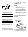
Changing the broil orifice, on
GAS ranges only (PRG models)
9 CAUTION
After the replacement of the broiler orifice, and
before reassembly of the back panel and backguard to
the range, perform a brief gas leakage check of the
orifice and associated fittings, per the “Check for Gas
Leaks” section of these instructions.
Removing the backguard assembly
1. Move the range out of its installed position to gain full
access to the rear panel of the backguard assembly
and to the broil burners' orifices.
2. Use a T-20 torx screwdriver to remove the screws from
the front of the backguard assembly.
3. Use a T-20 torx screwdriver to remove the screws from
the back rear panel of the backguard assembly.
4. Carefully lift the backguard assembly from the range.
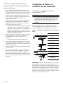
Changing the broil burner orifice
NOTE: This procedure applies to both the main oven broil
burner and, when applicable, to the auxiliary oven broil
burner.
1. Remove broil orifice using a 7/16'' box end wrench,
while restraining the elbow fitting from rotation using
a small adjustable wrench.
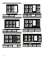
Model 606 with griddle
(1) 105 (3) 105
(5) —
(6) 105
(2) 126 (4) 115 (7) 115
33
44
66
77
11
22
55

Page. 16
IMPORTANT: DO NOT bend the broil burner orifice
bracket. Ensure that the broiler orifice is aligned to the
center of the burner tube inlet.
2. Label each of the removed orifices, noting from which
burner they were removed, in the event the appliance
is converted back to natural gas in the future.
For your convenience, note the orifice sizes and
locations in the following table.
3. Locate the proper burner orifices included with the kit.
Orifices are stamped with the orifice diameter size on
the side.
4. Replace orifices as indicated in the table. To avoid any
possible gas leak in this area, ensure the orifice is
completely seated and tight to the burner orifice
holding bracket and the 90° orifice elbow.
NOTE: The replacement broil orifices have straight
threads (not tapered threads) and DO NOT require thread
sealing compound.
5. Continue to “Removing and installing the oven
door(s), on GAS ranges only (PRG models)” before
reattaching the backguard assembly. Once all of the
broil and bake burners' orifices have been replaced
and converted to LP gas, reinstall the oven doors
before performing a gas leak check of all the replaced
bake and broil orifices and their associated supply
tube fittings.
Removing and installing the
oven door(s), on GAS ranges
only (PRG models)
9 CAUTION
• USE CAUTION WHEN REMOVING THE DOOR.
THE DOOR IS VERY HEAVY.
• Make sure oven is cool and power to the oven has
been turned off before removing the door. Failure
to do so could result in electrical shock or burns.
• The oven door is heavy and fragile. Use both
hands to remove or replace the door.
• Failure to grasp the oven door firmly and properly
could result in personal injury and product
damage.
• With the door off, never release the levers and try
to close the hinges. Without the weight of the
door, the powerful springs will snap the hinges
closed with great force.
To gain access to the bake burner orifices, you will need to
remove the oven door, kick panel, and the bottom front
panel, if applicable.
Removing the oven door
1. Open the door fully. Flip the hinge clips down for both
sides of the door. A screwdriver may be required to
carefully pry the clip back.
2. Close the door gently until it stops against the hinge
clips. The open hinge clips will hold the door open at
a slight angle, about 30°, from the closed position.
Main oven broil Aux oven broil
Description Main oven broil Aux oven broil
Pro Grand 1.25 mm (125) 0.813 mm (813) or “67”
Pro Harmony 1.25 mm (125) 0.75 mm (75)

Page. 17
3. Grasp the door firmly on the ends of the door. Lift the
door up and out. There will be some spring resistance
to overcome.
4. Place the door in a safe and stable location.
Reinstalling the oven door before leak
testing the broil and bake burners
After replacing the bake burner orifices and the appliance
satisfactorily gas leak tested, the oven door, kick panel,
and the bottom front panel must be reinstalled.
1. Hold the door firmly in both hands.
2. Hold the door at a 30° angle from the closed position.
Insert hinges centered evenly into the hinge slots. The
hinges will securely hook into the slots when properly
installed. DO NOT force, bend or twist the door.
3. Open door fully to expose hinges, levers, and slots.
4. Flip the hinge forward until seated on the bracket. A
screwdriver may be required to carefully push the clip
back.
5. Close and open the door slowly to ensure it is
correctly and securely in place.
Removing the kick and front panels
1. Remove the kick panel screws using a T-20 torx
screwdriver.
2. Remove the front panel screws using a T-20 torx
screwdriver.

Page. 18
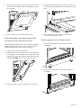
Changing the bake orifice, on
GAS ranges only (PRG models)
Changing the main oven bake burner
orifice
IMPORTANT:
• Do not bend the bake burner tube.
• Do not bend the bake burner gas tube.
• Do not modify the shutter opening. The air shutter
should remain fully open.
• Do not remove the anti-rotation bracket when
performing the orifice change. This bracket is
critical to the alignment of the bake burner tube
with the burner orifice. After the orifice
replacement, this bracket will facilitate the burner
tube’s realignment.
1. Remove the bake gas line using a 13/16'' box end
wrench.
2. Remove the two screws from the bake burner tube
mounting bracket with a T-20 torx driver.
4. Replace the orifice as indicated in the table.
5. Ensure that the bake orifice is aligned to the center of
the burner tube inlet. Reinstall the bake burner tube
beneath the oven. If necessary, use a flashlight to aid
in seeing the locating slot where the burner tube sits
at the backside of the burner cavity.
6. Slide the elbow fitting back into the anti-rotation
bracket. Reattach the two bake burner mounting
bracket screws and tighten the gas line.
7. If the gas range is a single oven, perform a gas
leakage check of the orifice and associated supply
tube fittings per “Checking for gas leaks” on page 19.
If the gas range has an auxiliary oven, proceed with
the following instructions.
Changing the auxiliary oven bake burner
orifice
IMPORTANT:
• Do not bend the bake burner tube.
• Do not bend the bake burner gas tube.
• Do not modify the shutter opening. The air shutter
should remain fully open.
1. Remove the two screws from the auxiliary bake burner
mounting bracket with a T-20 torx driver. Pull the
bracket and gas line carefully towards you.
NOTE: It is not necessary to loosen the auxiliary oven
bake gas line.
a. Anti-rotation bracket b. Bake gas line
c. Elbow fitting d. Shutter
e. Bake burner tube
mounting bracket
f. Bake burner tube
3. Insert a 1/2'' offset
wrench into the
shutter opening to
restrain the bake
orifice while hand
twisting the orifice
elbow
counterclockwise.
a e f
cb
d
Description Main oven bake
Pro Grand 1.46 mm (146)
Pro Harmony 1.34 mm (134)
a. Auxiliary bake burner
mounting bracket
b. Aux oven bake gas
line
c. Elbow fitting d. Bake burner tube
a
c
b
d

Page. 19
2. With an adjustable wrench, restrain the elbow fitting.
With a 1/2'' offset wrench, unscrew the auxiliary bake
burner orifice.
For your convenience, note the orifice sizes and
locations in the following table.
3. Replace the orifice as indicated in the table.
NOTE: The replacement bake orifices have straight
threads (not tapered threads) and DO NOT require thread
sealing compound.
4. Before reattaching the auxiliary bake burner mounting
bracket, perform a gas leakage check of the orifice
and associated supply tube fittings per “Checking for
gas leaks”.
Checking for gas leaks
9 WARNING
DO NOT use a flame of any kind to check for gas
leaks.
9 CAUTION
DO NOT spray water solution onto exposed electrical
components. If solution does drip onto electrical
components, shut the power off before wiping off the
electronics.
9 CAUTION
Ensure that the STAR burner igniter wire terminals do
not touch the chassis metal, or any metal part, to
prevent sparking. Do not touch the igniter wires while
the burner is turned on to avoid being shocked.
Leak testing should occur after the orifices are replaced
and before the appliance is fully reassembled. However,
the doors of the appliance must also be installed and
closed in order to leak check the broil and bake burners.
Leak testing of the appliance shall be conducted
according to the following instructions.
Gas leak checking the rangetop STAR
®
burners
To leak check the rangetop’s STAR burners
1. Make sure that the orifices have been tightened and
that all valves and controls are in the OFF position.
2. Turn on electric and gas supplies.
3. Spray a generous amount of soap and water
mixture—or other solution designed for checking gas
leaks—on the threaded junction at the base of the
orifice, the elbow fitting, and gas tube compression
nut. (A 25% dishwashing liquid to water mixture is
effective for this.) Avoid spraying electrical
components.
4. Turn the corresponding STAR burner knob to HI while
firmly blocking the STAR burner's orifice hole with a
soft rubber pencil eraser, your finger, or something
similar.
5. Monitor the base of the orifice junction, elbow fitting,
and compression nut to see if bubbles are forming
anywhere around the connections.
• Bubbles forming are indications of gas leaks.
6. If appliance leaks, repair all gas leaks immediately. Do
not over-torque the junctions, orifices or nuts, or bend
the gas tubes.
7. Repeat for all STAR burners.
Gas leak checking the broil orifice(s)
To leak check the broil burner orifice(s)
1. Spray a generous amount of soap and water
mixture—or other solution designed for checking gas
leaks—on the threaded junction at the base of the
orifice, the elbow fitting, and gas tube compression
nut. (A 25% dishwashing liquid to water mixture is
effective for this.) Avoid spraying electrical
components.
Main oven bake Aux oven bake
Description Auxiliary oven bake
Pro Grand 1.13 mm (113)
Pro Harmony 0.75 mm (75)

Page. 20
2. Turn the mode knob and the oven temperature knob
to BROIL while blocking the broil orifice hole with a
soft pencil eraser, your finger, or something similar.
• There will be a delay of approximately 45 to 90
seconds as the safety valve coil heats to release
the valve’s actuator. A single pop noise can usually
be heard as the broiler’s safety valve opens.
3. Monitor the base of the orifice junction, elbow fitting,
and compression nut to see if bubbles are forming
anywhere around the connections.
• Bubbles forming are indications of gas leaks.
4. If appliance leaks, repair all gas leaks immediately. Do
not over-torque the junctions, orifices or nuts, or bend
the gas tubes.
5. If applicable, repeat for the auxiliary broil orifice.
Gas leak checking the bake orifice(s)
To leak check the oven bake burner orifice(s)
1. Spray a generous amount of soap and water
mixture—or other solution designed for checking gas
leaks—on the threaded junction at the base of the
orifice, the elbow fitting, and gas tube compression
nut. (A 25% dishwashing liquid to water mixture is
effective for this.) Avoid spraying electrical
components.
2. Turn the mode knob to BAKE and the oven
temperature knob to any setting while blocking the
bake orifice hole with your finger.
• There will be a delay of approximately 45 to 90
seconds as the safety valve coil heats to release
the valve’s actuator. A single pop noise can usually
be heard as the broiler’s safety valve opens.
3. Monitor the base of the orifice junction, elbow fitting,
and compression nut to see if bubbles are forming
anywhere around the connections.
• Bubbles forming are indications of gas leaks.
4. If appliance leaks, repair all gas leaks immediately. Do
not over-torque the junctions, orifices or nuts, or bend
the gas tubes.
5. If applicable, repeat for the auxiliary bake orifice.
6. If the appliance has been satisfactorily leak checked,
turn off the gas and electric supplies. Reinstall the
auxiliary bake burner mounting bracket, if applicable,
and continue to “Checking the flame and burner
performance”.
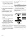
Checking the flame and burner
performance
Checking the STAR
®
burner performance
9 WARNING
When cooking with the STAR burners, the burner
flame size should be adjusted so it does not extend
beyond the edge of the cooking utensil. This
instruction is based on safety considerations.
To observe the burner flames, it may be necessary to turn
off lights or close window blinds to darken the room for
easier viewing of the flame.
Reassemble the rangetop as follows:
TIP: Use the burner venturi as a centering guide when
remounting the burner pedestals. If the pedestals are
centered, the venturi will slide in and out easily after the T-
30 torx head screw has been secured. If the pedestals are
not centered properly, loosen the mounting screw and
recenter the burner until the venturi slides freely.
a. Grate
b. Burner cap
c. Venturi
d. Burner base
e. Electrode
f. Burner pedestal
g. Spill tray
h. Heat shield
i. Igniter housing
j. Igniter wire
d
b
a
e
f
g
h
c
i
j
La page est en cours de chargement...
La page est en cours de chargement...
La page est en cours de chargement...
La page est en cours de chargement...
La page est en cours de chargement...
La page est en cours de chargement...
La page est en cours de chargement...
La page est en cours de chargement...
La page est en cours de chargement...
La page est en cours de chargement...
La page est en cours de chargement...
La page est en cours de chargement...
La page est en cours de chargement...
La page est en cours de chargement...
La page est en cours de chargement...
La page est en cours de chargement...
La page est en cours de chargement...
La page est en cours de chargement...
La page est en cours de chargement...
La page est en cours de chargement...
La page est en cours de chargement...
La page est en cours de chargement...
La page est en cours de chargement...
La page est en cours de chargement...
La page est en cours de chargement...
La page est en cours de chargement...
La page est en cours de chargement...
La page est en cours de chargement...
La page est en cours de chargement...
La page est en cours de chargement...
La page est en cours de chargement...
La page est en cours de chargement...
La page est en cours de chargement...
La page est en cours de chargement...
La page est en cours de chargement...
La page est en cours de chargement...
La page est en cours de chargement...
La page est en cours de chargement...
La page est en cours de chargement...
La page est en cours de chargement...
La page est en cours de chargement...
La page est en cours de chargement...
La page est en cours de chargement...
La page est en cours de chargement...
La page est en cours de chargement...
La page est en cours de chargement...
La page est en cours de chargement...
La page est en cours de chargement...
La page est en cours de chargement...
-
 1
1
-
 2
2
-
 3
3
-
 4
4
-
 5
5
-
 6
6
-
 7
7
-
 8
8
-
 9
9
-
 10
10
-
 11
11
-
 12
12
-
 13
13
-
 14
14
-
 15
15
-
 16
16
-
 17
17
-
 18
18
-
 19
19
-
 20
20
-
 21
21
-
 22
22
-
 23
23
-
 24
24
-
 25
25
-
 26
26
-
 27
27
-
 28
28
-
 29
29
-
 30
30
-
 31
31
-
 32
32
-
 33
33
-
 34
34
-
 35
35
-
 36
36
-
 37
37
-
 38
38
-
 39
39
-
 40
40
-
 41
41
-
 42
42
-
 43
43
-
 44
44
-
 45
45
-
 46
46
-
 47
47
-
 48
48
-
 49
49
-
 50
50
-
 51
51
-
 52
52
-
 53
53
-
 54
54
-
 55
55
-
 56
56
-
 57
57
-
 58
58
-
 59
59
-
 60
60
-
 61
61
-
 62
62
-
 63
63
-
 64
64
-
 65
65
-
 66
66
-
 67
67
-
 68
68
-
 69
69


Thermador PALPKITGW Guide d'installation
- Catégorie
- Cuisinières
- Taper
- Guide d'installation
- Ce manuel convient également à
dans d''autres langues
Documents connexes
-
Thermador PALPKITHW Guide d'installation
-
-
-
Thermador PAALTKITGW Guide d'installation
-
-
-
-
-