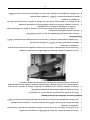
VULCAN & WOLF Endurance Challenger Range Le manuel du propriétaire
- Catégorie
- Micro-ondes
- Taper
- Le manuel du propriétaire

ITW Food Equipment Group, LLC
3600 North Point Blvd
Baltimore, MD 21222
RETAIN THIS MANUAL FOR FUTURE USE
FORM F38201 Rev. F (01-21)
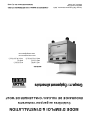
INSTALLATION &
OPERATION MANUAL
VULCAN ENDURANCE / WOLF CHALLENGER
Gas Restaurant Ranges
MODELS:
12(F) 24S(F)
36(S,C,R)(F)
48(S,C,R)(F)
48SS(F)
60(S,C,R)(S,C,R)(F)
72(S,C,R)(S,C,R)(F)
www.vulcanequipment.com
www.wolfequipment.com

- 2 -
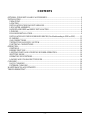
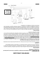
IMPORTANT FOR YOUR SAFETY
THIS MANUAL HAS BEEN PREPARED FOR PERSONNEL QUALIFIED TO INSTALL GAS
EQUIPMENT, WHO SHOULD PERFORM THE INITIAL FIELD START-UP AND
ADJUSTMENTS OF THE EQUIPMENT COVERED BY THIS MANUAL.
POST IN A PROMINENT LOCATION THE INSTRUCTIONS TO BE FOLLOWED IN THE
EVENT THE SMELL OF GAS IS DETECTED. THIS INFORMATION CAN BE OBTAINED
FROM THE LOCAL GAS SUPPLIER.
IMPORTANT
In the event a gas odor is detected, shut
down units at main shutoff valve and
contact the local gas supplier for service.
FOR YOUR SAFETY
Do not store or use gasoline or other
flammable vapors or liquids in the vicinity of
this or any other appliance.
Improper installation, adjustment, alteration,
service or maintenance can cause property
damage, injury or death. Read the
installation, operating and maintenance
instructions thoroughly before installing or
servicing this equipment.
IN THE EVENT OF A POWER FAILURE, DO NOT
ATTEMPT TO OPERATE THIS DEVICE.

- 3 -
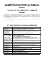
CONTENTS
OPTIONAL FIELD INSTALLABLE ACCESSORIES ............................................................................ 4
INSTALLATION ....................................................................................................................................... 5
UNPACKING ......................................................................................................................................... 5
LOCATION ............................................................................................................................................ 5
INSTALLATION CODES AND STANDARDS ................................................................................... 6
LEG/CASTER ASSEMBLY .................................................................................................................. 6
BACKSPLASH RISER and SHELF INSTALLATION ........................................................................ 8
LEVELING ............................................................................................................................................. 9
BULLNOSE INSTALLATION.............................................................................................................. 9
INSTALLATION OF GRIDDLE/BROILER BRICKS (For Models ending in GBN or GBP) .......... 12
PLUMBING .......................................................................................................................................... 12
GAS CONNECTIONS ......................................................................................................................... 13
TESTING THE GAS SUPPLY SYSTEM ........................................................................................... 13
ELECTRICAL CONNECTIONS ......................................................................................................... 13
OPERATION ............................................................................................................................................ 14
CONTROLS ......................................................................................................................................... 14
BEFORE FIRST USE ........................................................................................................................... 14
LIGHTING PILOTS AND VERIFYING BURNER OPERATION .................................................... 15
SHUTTING DOWN ............................................................................................................................. 18
OPERATING SUGGESTIONS............................................................................................................ 18
LOADING AND UNLOADING THE OVEN ..................................................................................... 19
CLEANING .............................................................................................................................................. 19
DAILY CLEANING ............................................................................................................................. 20
EXTERIOR CLEANING ..................................................................................................................... 21
MAINTENANCE & ADJUSTMENTS .................................................................................................... 22
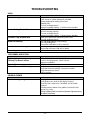
TROUBLESHOOTING ............................................................................................................................ 23

- 4 -
INSTALLATION, OPERATION AND CARE OF VULCAN
ENDURANCE / WOLF CHALLENGER GAS RESTAURANT
RANGES
PLEASE KEEP THIS MANUAL FOR FUTURE USE
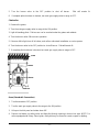
GENERAL
Vulcan Endurance and Wolf Challenger ranges and ovens are produced with quality workmanship and
material. These ranges are designed with efficiency in cooking performance, sanitation and ease of
cleaning ability in mind. Proper installation, usage and maintenance of your range will result in many
years of satisfactory performance.
The manufacturer suggests that you thoroughly read this entire manual and carefully follow all of the
instructions provided.
Reference manual F961533 for refrigerated base setups.
OPTIONAL FIELD INSTALLABLE ACCESSORIES
ACCESSORY CODE
DESCRIPTION
3/4QDH-4FT
1INFLEX-4FT
¾" (18.75 mm) flex hose / quick disconnect 4’ (1219 mm long).
1" (25 mm) flex hose / quick disconnect, 4' (1219 mm) long.
ALTIKIT-CARN
(01,03,05,07,09)
ALTIKIT-CARP
(02,04,06,08,10)
Altitude Kit - Available in Natural Gas or Propane (LP) for the following
altitudes:
0-1999 ft, 2000-3999 ft, 4000-5999, 6000-7999, 8000-9999.
CASTERS-RR4
CASTERS-ADJRR4
Set of four (4) standard casters.
Set of four (4) adjustable casters.
Two (2) sets required for 48", 60", and 72" ranges
CONNECT-CHALL
Inter-Plumb kit for connecting for Salamander/Cheesemelter to range.
OVNRACK-XL(20,26)
1 extra oven rack.
1 pair of rack guides (set of 2).
CURBMNT-XL4
Curb mounting kit. Two (2) sets required for 48", 60", and 72" ranges.
OTB-STEPUP
Step up rear burner 4”. One kit needed per burner.
RCCONRL-
(24,36,48,60,72)
Condiment Rail Assembly - Replaces standard bullnose. Available for 24",
36", 48", 60", and 72" ranges. (Does not include condiment pans)
RCTWLBR-
(24,36,48,60,72)
Towel Bar Assembly - Replaces standard bullnose. Available for 24", 36", 48",
60", and 72" ranges.
RSHELF-XL
(24,36,48,60,72)
Reinforced High Shelf - 23" (584 mm) high stainless steel backsplash with
broiler mounting brackets for Salamander/Cheesemelter.
SHIELD-FRYRH
SHIELD-FRYLH
Fryer Splash Shield - Right hand or left hand side. Protects range top against
grease splatter from adjacent fryer.
STUB10-XL
(24,36,48,60,72)
10" Stainless steel stub riser. Available for 24", 36", 48", 60", and 72" ranges.
12” ranges ship standard with 10” stub riser.

- 5 -
VFLANGED-FEET/4
Set of four (4) flanged feet. Two (2) sets required for 48", 60", and 72" ranges.
INSTALLATION
UNPACKING
This range was inspected before leaving the factory. The transportation company assumes full
responsibility for safe delivery upon acceptance of the shipment. Immediately after unpacking, check for
possible shipping damage. If the range is found to be damaged, save the packaging material and
contact the carrier within 5 days of delivery.
Carefully unpack range(s) and place in the approximate installation position. Remove parts packed in a
small cardboard box from oven cavity or shipped separately in finishing kit.
If burner has been shipped using any package strapping devices, remove these before installing the
range.
Before installing, check the type of gas supply (natural or propane) to make sure they agree with the
specifications on the rating plate located on the inside of the kick panel. If the supply and equipment
requirements do not agree, do not proceed with the installation. Contact your dealer immediately.
LOCATION
The equipment area must be kept free and clear of combustible substances.
Installation clearances: COMBUSTIBLE NON-COMBUSTIBLE
CONSTRUCTION CONSTRUCTION
Back: 6" (152 mm) 0"
Right Side: 10" (254 mm) 0"
Left Side: 10" (254 mm) 0"
The installation location must allow adequate clearances for servicing and proper operation.
The ranges are suitable for installation on combustible floors when 6" (152 mm) adjustable legs or
casters are used. When legs or casters are removed, use only on noncombustible floors, curb, or
platform, with front appliance base projecting 3" (76 mm) beyond curb or platform.
The range(s) must be installed so that the flow of combustion and ventilation air will not be obstructed.
Adequate clearance for air openings into the combustion chamber(s) must be provided. Make sure
there is an adequate supply of air in the room to allow for combustion of the gas at the burners.

- 6 -
INSTALLATION CODES AND STANDARDS
Your Vulcan Endurance / Wolf Challenger Range must be installed in accordance with:
In the United States of America:
1. State and local codes.
2. National Fuel Gas Code, ANSI-Z223.1/NFPA #54 (latest edition). This shall include but
not be limited to: NFPA #54 Section 10.3.5.2 for Venting. Copies may be obtained
from The American Gas Association Accredited Standards Committee Z223, @ 400 N.
Capital St. NW, Washington, DC 20001 or the Secretary Standards Council, NFPA, 1
Batterymarch Park Quincy, MA 02169-7471.
NOTE: In the Commonwealth of Massachusetts
All gas appliances vented through a ventilation hood or exhaust system equipped with
a damper or with a power means of exhaust shall comply with 248 CMR.
3. NFPA Standard # 96 Vapor Removal from Cooking Equipment, latest edition, available
from the National Fire Protection Association, Batterymarch Park, Quincy, MA 02269.
In Canada:
1. Local codes.
2. CAN/CSA-B149.1 Natural Gas Installation (latest edition)
3. CAN/CSA-B149.2 Propane Installation Code (latest edition), available from the
Canadian Gas Association, 178 Rexdale Blvd., Etobicoke, Ontario, Canada M9W 1R3
The above are available from the Canadian Standard Association, 5060 Spectrum Way, Suite 100,
Mississauga, Ontario, Canada L4W 5N6.
LEG/CASTER ASSEMBLY
The range is provided with 6"(152 mm) adjustable stainless steel legs (hardware included), packaged in
a box located inside of the oven or in a finishing kit. A set of 6"(152 mm) casters (adjustable or non-
adjustable) are available as an optional field installable accessory.
RANGE SERIES (width)
LEGS TO INSTALL
CASTERS TO INSTALL
12"
4
4
24"
4
4
36"
4
4
48"
8
8
60"
8
8
72"
8
8
Installation of Legs/Casters:
1. Carefully tip range on its side or back. Rear flue assembly can be removed to avoid damage.

- 7 -
2. Align holes in leg/caster mounting plate with pre-drilled holes on the bottom of range located in
each of the four corners. Four additional legs/casters must be installed on the 48", 60", and 72"
ranges.
3. Attach mounting plate to bottom of range using four (4) ¼ - 20 x ¾“ thread cutting screws
(provided). If casters are being installed, the locking casters should be mounted on the front.
4. After all legs/casters have been installed, carefully return the range to its upright position.
(For additional leg information, see “LEVELING” section of this manual).
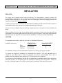
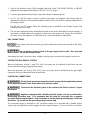
Ranges mounted on casters must use a flexible connector (not included) that complies with the
Standard for Connectors for Movable Gas Appliances, ANSI Z21.69•CSA 6.16 and a quick-disconnect
device that complies with the Standard for Quick-Disconnect Devices for Use With Gas Fuel, ANSI
Z21.41•CSA 6.9.
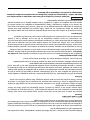
In addition, adequate means must be provided to limit movement of the appliance without depending on
the connector and the quick-disconnect device or its associated piping to limit appliance movement.
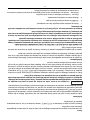
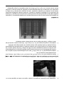
Attachment points are available on the rear of the range including a strap clamp (for connection of a
restraint) and the backsplash channel thru holes.
If disconnection of the restraint is necessary, turn off the gas supply before disconnection. Reconnect
this restraint prior to turning the gas supply on and returning the range to its installation position.
If the range is installed on casters and is moved for any reason, it is recommended that the range be
re-leveled front to back and side to side for even baking.
Strap Clamp
Backsplash
Channel

- 8 -
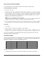
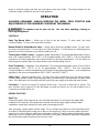
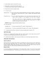
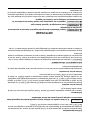
BACKSPLASH RISER and SHELF INSTALLATION
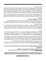
1. Engage Tab on Backsplash Channels into the slots in the back of the Frame (shown) so that
Backsplash freely hangs in place. The Backsplash front will lip over most, but not all, griddle
configurations.
2. Install Screws to secure Channels to Frame (QTY 4 per Channel). All Screws are #10-24 x ½
unless noted otherwise.
3. Install Screws to secure Backsplash to Flue Exhaust (QTY 2 per Flue Exhaust).
4. Install Shelf over the top of the Back Splash; ensure the Channel on the top of the Shelf
engages the top flange of the Backsplash. Secure with ¼-20 Bolts/Nuts provided (Qty 4).
NOTE:
• Reinforced Riser and Shelf Installation Instruction is supplied separately, 921132.
• Shelves cannot be installed over charbroilers. Intermediate shelf bracket, 922416, and
installation instruction, 922417, are supplied separately.
DO NOT obstruct the flow of flue gases from the flue located on the rear of the range. Proper venting
of flue gas is vital to the safe and efficient operation of the range. Problems arising from the intentional
obstruction of the flue will result in voiding of warranty. It is recommended that the flue gases be
ventilated to the outside of the building through a ventilation system installed by qualified personnel.
From the termination of the flue to the filters of the hood venting system, a minimum clearance of 18"
(457 mm) must be maintained. Information on the construction and installation of ventilating hoods
1
2
3
4
Flue
Exhaust
Channel
Tab

- 9 -
may be obtained from the standard for "Vapor Removal from Cooking Equipment," NFPA No. 96 (latest
edition), available from the National Fire Protection Association, Batterymarch Park, Quincy, MA 02269.
LEVELING
To level the range, place a carpenter's level on the range top and check leveling of the unit side to side
and front to rear. Achieve leveling by turning each foot section of the unit's leg as needed. Turning the
foot in a counter clockwise direction will increase height and clockwise will decrease.
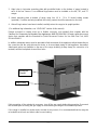
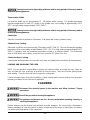
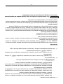
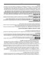
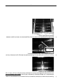
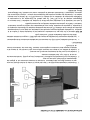
BULLNOSE INSTALLATION
1.) Remove Grate Castings along the front of edge of the Range.
2.) Slide Bullnose over mounting bracket and align with Range so that it is not offset in either
direction.
3.) Start screw at one end of the Range, do not tighten completely.
4.) Going across the width of the Range install the next screw, as shown in Figure 2, set the
alignment and tighten screw completely.
5.) Install the remaining screws and tighten all screws completely.
Condiment Rail
(Accessory)
Towel Bar
(Accessory)
Standard
Bullnose
Remove Grates
on Gas Range
Figure 1

- 10 -
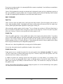
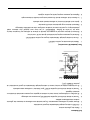
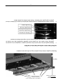
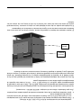
Re-install the Grate Castings along the front edge of the range.
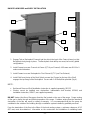
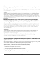
MOTOR ASSEMBLY INSTALLATION INSTRUCTIONS
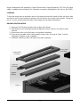
1. Remove the oven racks and the box containing legs, regulator and plumbing fittings. In some
instances, the legs, regulator and plumbing fittings will be shipped in separate finishing kit. Check
that all the listed components shown in figure are present.
2. Remove the packaging and motor grease guard from inside the oven and slide out the rack
guides. Tip the Motor Assembly to upright position.
Install Screws, #10-24 x
½ Phillips Head, in slots
on Bullnose as noted.
Note: Align the end of
the Bullnose with the
Range for fit.
Figure 2
LH Rack Guide
Motor Grease Guard
RH Rack
Guide
Motor Assembly
AssssGuaGreGuard

- 11 -
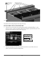
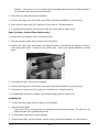
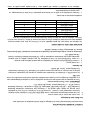
3. Push the motor assembly to the rear in the oven cavity, taking care not to pinch the power cord or
the wiring conduit. Assemble the motor assembly from the inside of the oven and the blower
cover with #10-24 (or #10-32) x ½ Phillips truss head screws provided in the hardware bag.
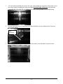
4. Ensure that blower cover is assembled such that air deflector is to the bottom side of the oven.
(See picture below).
5. Assemble rack guides by inserting the two tabs into slots on the side wall. Insert oven racks.
Air
Deflector

- 12 -
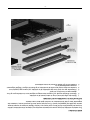
6. Assemble the motor grease guard from the rear of the unit with QTY 4 #10-24 x ½ screws.
INSTALLATION OF GRIDDLE/BROILER BRICKS (For Models ending in GBN or GBP)
1. Remove six 5 ¼” x 2 ¼” (133 x 57 mm) and six 5 ¼” x 5 1∕16” (133 x 129 mm) bricks from the
shipping box packaged in the oven cavity.
2. Install the 5 ¼” x 2 ¼” (133 x 57 mm) bricks to the left and right hand sides of the broiler by
inserting the bricks individually through the front opening in the broiler. Angle the brick
sideways for easy fit between the burner edges. Set the bricks flat in place, resting on the
broiler side and burner edges. Push each brick as far to the rear of the broiler as possible to
ensure easy fit of the last brick.
3. Install the remaining six 5 ¼” x 5 1∕16” (133 x 129 mm) bricks to the center section as described
in step 2. Place the bricks on the center burner edges only.
PLUMBING
A preset gas pressure regulator and plumbing fittings are shipped uninstalled. This regulator must be
installed by an authorized service person before the unit is placed into operation. See full unit data plate
located on the rear of the range, or the secondary data plate, riveted to the kick panel, for pressure
regulator setting information. If a manometer is being used, utilizing one of the available pressure taps
in the manifold, the manifold pressure with one burner on should be ± 0.3" W.C. of the value indicated
on the rating plate.

- 13 -
1. Refer to the Modular Range Field Plumbing Reference Guide (P/N 921861, 962356, or 960167)
shipped with the regulator and fittings for 48", 60", and 72" ranges.
2. Cover the pipe threads with pipe joint compound resistant to propane gases.
3. For 12", 24", and 36" ranges, screw the reducer, pipe nipple, and regulator onto the pipe with the
regulator flow direction arrow pointing towards the back of the unit and the regulator adjustment in
the upright position.
For 48", 60", and 72" ranges, follow the assembly steps as detailed in the Modular Range Field
Plumbing Reference Guide.
4. The pressure regulator must be mounted horizontally to ensure the leak limiter functions properly. A
leak limiter is supplied with every regulator to allow excess gas pressure to escape. Do not obstruct
the limiter or the gas regulator, as obstruction may cause the regulator to malfunction.
GAS CONNECTIONS
All gas supply connections and any pipe joint compound used must be resistant to the action
of propane gases.
Prior to lighting, check all joints in the gas supply line for leaks. Use soap and
water solution. Do not use an open flame.
After piping has been checked for leaks, all piping receiving gas should be fully purged to remove air.
TESTING THE GAS SUPPLY SYSTEM
When test pressures exceed ½ psig (3.45 kPa), the range and its individual shutoff valve must be
disconnected from the gas supply piping system.
When test pressures are ½ psig (3.45 kPa) or less, the range must be isolated from the gas supply
system by closing its individual manual shutoff valve.
ELECTRICAL CONNECTIONS
Electrical and grounding connections must comply with the applicable portions
of the National Electrical Code and/or other local electrical codes.
Disconnect the electrical power to the machine and follow Lockout / Tagout
procedures.
Appliances equipped with a flexible electrical supply cord are provided with a
three-prong grounding plug. It is imperative that this plug be connected into a properly
grounded three-prong receptacle. If the receptacle is not the proper grounding type, contact an
electrician. Do not remove the grounding prong from this plug.
The convection range is designed for 120 volt power supply and is provided with a flexible electric
supply cord and plug that must be plugged into the proper receptacle. Do not connect the convection

- 14 -
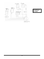
range to electrical supply until after gas connections have been made. The wiring diagram for the
convection range is located on the rear of the appliance.
OPERATION
QUALIFIED PERSONNEL SHOULD PERFORM THE INITIAL FIELD START-UP AND
ADJUSTMENTS OF THE EQUIPMENT COVERED BY THIS MANUAL.
The appliance and its parts are hot. Use care when operating, cleaning, or
servicing the appliance.
CONTROLS
Open Top Burner Valve — Allows gas to flow to the top burners. To open valve, turn knob
counterclockwise. To close valve, turn knob clockwise.
Manual Griddle & Griddle/Broiler Valve — Allows gas to flow to the griddle burners. To open valve,
turn knob counterclockwise. To close valve, turn knob clockwise. Turn the burner on full during burner
ignition then turn it back down to your desired setting once lit.
Thermostatic Griddle Control — Regulates griddle temperature. The thermostat temperature range is
from LOW at approximately 200°F (93°C) to HI at approximately 550°F (288°C). Turn the thermostat
clockwise to increase temperature and counterclockwise to decrease temperature. Turn the burner on
full during burner ignition then turn it back down to your desired setting once lit.
Oven Thermostat — Regulates oven temperature. The thermostat temperature range is from LOW at
approximately 250°F (121°C) to HI at approximately 500°F (260°C). Turn the thermostat
counterclockwise to increase temperature and clockwise to decrease temperature. Oven temperature
regulation is the most accurate between 300°F (149°C) and 500°F (260°C).
Safety Valve – Monitors standing pilot. All ovens and select griddle and open top burner devices
(Flame Safety models) feature a standing pilot that is monitored by a thermocouple and pilot safety
valve. If the pilot goes out, the safety valve will shut-off the gas supply to the pilot and main burners.
Fan Switch – Turns fan on and off (Convection Ovens only). Fan turns on when door is closed. Fan
turns off when door is opened. The fan will always run when the Oven is on. It is not possible to run a
Convection oven with the fan off.
BEFORE FIRST USE
Open Top
Remove top grates from range top to carry out initial seasoning. Do not season the grates while
installed on the range top. Once grates are removed from range, apply a light coating of liquid
vegetable or spray-type cooking oil to each grate (seasoning process).
After seasoning, replace grates onto the range. Turn on all open top sections to LOW and allow to burn
for at least 15 minutes before using pots or pans on the range top. Failure to season grates will cause
grates to rust. Upon initial use, grates may show white coloring. This will go away over time with proper
seasoning care. Use of water and a wire or stiff brush on the grate, followed by immediate drying before
the next seasoning will help preserve the cast iron color.

- 15 -
Ovens
New ovens require a burn off period to break in the oven and eliminate unappetizing odors from
penetrating the food product.
Turn on gas to unit and set the thermostat to 475°F (246°C). Allow the oven to operate at this
temperature for 30 to 45 minutes.
Griddles
Before leaving the factory the griddle is coated with food grade lubricants as a rust inhibitor. Remove
this film when the griddle plate is being cleaned prior to its first cooking use. Heat the griddle to 200-
300°F to loosen and melt the coating, then clean the surface with a non-corrosive, grease-dissolving
commercial cleaner, following the manufacturer’s directions. Rinse thoroughly and wipe dry with a soft
clean cloth. Clean all accessories.
The griddle plate is steel, but the surface is soft and can be scored or dented by
careless use of spatulas or scrappers. Be careful not to dent, scratch or gouge the plate. Do
not try to knock off loose food that may be on the spatula by tapping the corner edge of the
spatula on the griddle surface.
Season the griddle to avoid possible surface corrosion before first use, and after every cleaning. Heat
griddle to a low temperature (300-350°F) and apply a small amount of cooking oil – about one ounce
per square foot of surface. Use a soft lint-free cloth to spread the oil over the entire griddle surface to
create a thin film. Wipe off any excess oil with a cloth. Repeat the procedure until the griddle has a
slick, mirror-like finish.
Charbroilers
The top grates are shipped flat (top-side down) from the factory. Remove the cast iron grates and
radiants. Inspect and remove the shipping restraints used during shipping to hold the burners.
Reassemble the radiants and top grates.
Allow the charbroiler to preheat for 30 minutes. Rub grates with cooking oil before using.
LIGHTING PILOTS AND VERIFYING BURNER OPERATION
All burner configurations are equipped with standing pilots allowing for instant appliance use
and low maintenance. Lighting should be infrequent except during initial start-up or full
appliance shut-down.
Pilot safety monitoring is standard on all ovens and is optional for open top burner and griddle
devices (Flame Safety models). Manual piezo ignition may be provided.
Open Top Burner, Griddle (see next section for Flame Safety models)
1. Remove front row of grates (Open Top Only).
2. Turn the main gas supply valve to range to the ON position.
3. Light all standing pilots.
Open Top Burners - Pilot access can be reached under the grates.

- 16 -
Griddles – Pilot access can be reached under the griddle plate through the slotted opening in
the manifold cover near the burner valve knob.
4. Turn the burner valve ON to ensure operation.
5. If burners fail to light, turn off all valves, and call an authorized installation or service person.
6. Turn the burner valve to the OFF position to shut off burner. Pilot will remain lit.
7. If complete pilot shut down is desired, turn main gas supply valve to range to OFF.
Open Top Burner, Griddle (Flame Safety models)
1. Remove front row of grates (Open Top Burners Only)
2. Turn the main gas supply valve to range to the ON position.
3. Depress and hold safety valve button and light pilot either conventionally by applying a flame or
using rotary piezo igniter. Repeat for each safety valve. Rotary piezo igniter operation is shown
below.
4. Turn the burner valve ON to ensure operation.
5. If burners fail to light, turn off all valves, and call an authorized installation or service person.
6. Turn the burner valve to the OFF position to shut off burner. Pilot will remain lit.
7. If complete pilot shut down is desired, turn main gas supply valve to range to OFF
Griddle/Broiler
1. Turn the main gas supply valve to range to the ON position.
2. Light all standing pilots.
Pilot access can be reached under the griddle through the broiler opening. The pilot is on the
bottom left side of the griddle/broiler burner.
3. Turn the burner valve ON to ensure operation.
4. If burners fail to light, turn off all valves, and then call an authorized installation or service person.

- 17 -
5. Turn the burner valve to the OFF position to shut off burner. Pilot will remain lit.
6. If complete pilot shut down is desired, turn main gas supply valve to range to OFF.
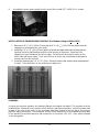
Charbroiler
1. Remove the grates.
2. Turn the main gas supply valve to range to the ON position.
3. Light all standing pilots. Pilot access can be reached under the grates and radiants.
4. Turn the burner valve ON to ensure operation.
5. If burners fail to light, turn off all valves, and call an authorized installation or service person.
6. Turn the burner valve to the OFF position to shut off burner. Pilot will remain lit.
7. If complete pilot shut down is desired, turn main gas supply valve to range to OFF.
Oven (Standard & Convection)
1. Turn thermostat to OFF position.
2. Turn the main gas supply valve to the range to the ON position.
3. Lift up on the kick panel and rotate down 90°.
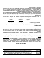
4. Depress red button on safety valve and light pilot through opening in burner box area. NOTE: For
ovens equipped with Rotary Piezo ignitor, rotary dial may be turned to create a spark for lighting.
Grate
Radiant
Burner
Deflector

- 18 -
5. Hold red button down for at least 30 seconds.
6. When button is released, pilot should remain lit.
7. Pilot flame must be high enough to heat thermocouple.
8. Return the kick panel to original position.
9. To Turn Oven On:
Standard Oven – Turn oven control dial to desired temperature and ensure operation. If ignition fails,
turn the oven control dial to OFF. Wait 5 minutes and repeat the above
procedure.
Convection Oven – Turn on fan switch located between oven control dial and pilot safety valve. This
switch must be flipped to ON, otherwise the oven will not operate.
Turn oven control dial to desired temperature and ensure operation
If ignition fails, turn the fan switch and oven control dial to OFF. Wait 5
minutes and repeat the above procedure.
DO NOT attempt to relight pilot without waiting 5 minutes.
10. To turn Oven Off:
Standard Oven – Turn oven control dial to OFF position. Pilot will remain lit.
Convection Oven – Turn oven control dial AND Fan switch to OFF position. Pilot will remain lit.
11. If complete pilot shut down is desired, turn main gas supply valve to range to OFF.
SHUTTING DOWN
All burners are equipped with standing pilots that remain lit when control valves are turned OFF.
Convection ovens will additionally need the fan switch turned OFF.
For complete range shutdown, and to extinguish all pilots, turn off main gas supply valve to range.
OPERATING SUGGESTIONS
Open-Top Burners
Open-top burners are quickly lit and require no preheating time. Open top burners have a wide low to
high burner flame adjustment range. This allows for better simmering performance at the lowest
possible stabilized setting. When simmering, turn the burner valve knob down until you reach the
optimum lowest burner flame setting to maintain the desired simmer point.
Manual Griddle
Pre-heat the griddle top for approximately 15 - 20 minutes before cooking. The top can be kept hot with
burners turned partially down. During off periods, turn the burners down or heat using only one burner.

- 19 -
Leaving burners at a high setting without a load for long periods of time may lead to
undesired plate appearance.
Thermostatic Griddle
Pre-heat the griddle top for approximately 15 - 20 minutes before cooking. The griddle thermostats
regulate temperatures for each 12" section of the griddle from a low setting at approximately 200°F
(93°C) to high setting at approximately 550°F (288°C).
Leaving burners at a high setting without a load for long periods of time may lead to
undesired plate appearance.
Charbroiler
Allow the charbroiler to preheat for 30 minutes. Rub grates with cooking oil before using.
Standard Oven Cooking
Allow time to preheat ovens before using (25 minutes to 400°F [204°C]). The oven thermostat regulates
temperature from a low setting at approximately 250°F (121°C) to high setting at approximately 500°F
(260°C). If properly used, the automatic temperature control is an efficient system. Turn thermostat
down to LOW when oven is idling, or turn the oven control to OFF when not in use.
Convection Oven Cooking
Cooking time and temperature in convection oven may vary slightly from normal time and temperature.
LOADING AND UNLOADING THE OVEN
NOTE: It is the operator’s responsibility to protect skin surfaces before accessing the oven. Open the
door and load the oven as quickly as practical to conserve heat. Take care to avoid spilling liquids
while loading. Close the door and refer to recipe for cooking time.
Provide adequate space for product unloading. Rapid unloading will conserve heat and ensure proper
reheating conditions for the next load, if applicable.
CLEANING
Disconnect the electrical power to the machine and follow Lockout / Tagout
procedures.
Shut off the gas before cleaning the appliance.
The appliance and its parts are hot. Be very careful when operating, cleaning, or
servicing the appliance.
Exterior surfaces may be cleaned using soft cloth and mild detergent. Do not use highly chlorinated or
alkaline detergents to clean the exterior or interior components of the range, as these types of solutions
can lead to early degradation of the component.

- 20 -
Do not use scouring powder. It is extremely difficult to remove completely. It can build up accumulations
that will damage the oven.
Vulcan / Wolf equipment is strongly constructed and is designed to give you long, satisfactory service at
low cost, provided you give it proper care. Frequent cleaning and occasional adjusting should reward
you with low operating and maintenance costs and faster, better service.
DAILY CLEANING
Open Top
Clean cast iron open top grates with a mild soap and water solution. Rinse thoroughly and dry with a
clean, water-absorbent towel. Immediately after drying (with grates still removed from the range top),
season grates lightly with liquid vegetable or spray-type cooking oil.
After seasoning, replace grates onto the range. Turn on all open top sections to LOW and allow them to
burn for at least 15 minutes before using pots or pans on the range top. Season the open top grates
after each cleaning. Failure to season grates will cause grates to rust.
Griddle Top
Clean the griddle regularly. A clean griddle looks better, lasts longer and performs better. To produce
evenly cooked griddle products, keep the griddle plate clean and free of carbonized grease. Carbonized
grease on the surface hinders the transfer of heat from the griddle surface to the food, resulting in
spotty browning and loss of cooking efficiency. Carbonized grease tends to cling to griddle foods, giving
them a highly unsatisfactory and unappetizing appearance.
After each use, clean the griddle with a scouring pad or flexible spatula.
Once a day, thoroughly clean the griddle back splash, sides and front.
Griddle Grease Can
Empty grease can as needed throughout the day and regularly clean at least once daily. The grease
can has a weep hole to indicate that grease tray is full. Remove, empty and wash grease can in the
same manner as an ordinary cooking utensil.
In addition to grease can cleaning, inspect and clean grease can cavity weekly, or as needed. Once
the unit is cool, use an appropriate brush, towel, or cleaning device to ensure all visible surfaces are
wiped clean and that any buildup is removed from the cavity. This includes the cavity top and around
the griddle chute.
Service calls resulting from failure to properly empty the grease can or from maintaining a clean grease
can cavity will not be covered under warranty.
La page est en cours de chargement...
La page est en cours de chargement...
La page est en cours de chargement...
La page est en cours de chargement...
La page est en cours de chargement...
La page est en cours de chargement...
La page est en cours de chargement...
La page est en cours de chargement...
La page est en cours de chargement...
La page est en cours de chargement...
La page est en cours de chargement...
La page est en cours de chargement...
La page est en cours de chargement...
La page est en cours de chargement...
La page est en cours de chargement...
La page est en cours de chargement...
La page est en cours de chargement...
La page est en cours de chargement...
La page est en cours de chargement...
La page est en cours de chargement...
La page est en cours de chargement...
La page est en cours de chargement...
La page est en cours de chargement...
La page est en cours de chargement...
La page est en cours de chargement...
La page est en cours de chargement...
La page est en cours de chargement...
La page est en cours de chargement...
La page est en cours de chargement...
La page est en cours de chargement...
La page est en cours de chargement...
La page est en cours de chargement...
-
 1
1
-
 2
2
-
 3
3
-
 4
4
-
 5
5
-
 6
6
-
 7
7
-
 8
8
-
 9
9
-
 10
10
-
 11
11
-
 12
12
-
 13
13
-
 14
14
-
 15
15
-
 16
16
-
 17
17
-
 18
18
-
 19
19
-
 20
20
-
 21
21
-
 22
22
-
 23
23
-
 24
24
-
 25
25
-
 26
26
-
 27
27
-
 28
28
-
 29
29
-
 30
30
-
 31
31
-
 32
32
-
 33
33
-
 34
34
-
 35
35
-
 36
36
-
 37
37
-
 38
38
-
 39
39
-
 40
40
-
 41
41
-
 42
42
-
 43
43
-
 44
44
-
 45
45
-
 46
46
-
 47
47
-
 48
48
-
 49
49
-
 50
50
-
 51
51
-
 52
52


VULCAN & WOLF Endurance Challenger Range Le manuel du propriétaire
- Catégorie
- Micro-ondes
- Taper
- Le manuel du propriétaire
dans d''autres langues
Autres documents
-
Vulcan 36S-36CB Le manuel du propriétaire
-
Vulcan HD Series Range Mode d'emploi
-
Vulcan Hart V24 Mode d'emploi
-
Vulcan-Hart 72(S,C)(S,C) Manuel utilisateur
-
Wolf Range C60(S,C)(S,C) Manuel utilisateur
-
Vulcan-Hart GHX60T Manuel utilisateur
-
Garland E20 Series Owner Instruction Manual
-
Vulcan 36RB Manuel utilisateur
-