Anthro Elevate II Adjusta Assembly Instructions Manual
- Catégorie
- Bureaux d'ordinateur
- Taper
- Assembly Instructions Manual

10450 SW Manhasset Dr. | Tualatin, OR 97062
Toll-free: 800.325.3841 | Fax: 800.325.0045 | email: [email protected] | anthro.com
Outside the U.S. | Tel: 503.691.2556 | Fax: 503.691.2409
Rev G, February 2016
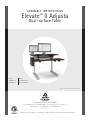
NOTE: The CPU SideRack - Inboard is not included.
Part # Product
MVJB48zz-xx ELT 2 Adjusta 48w
MVJB60zz-xx ELT 2 Adjusta 60w
Certification: Elevate II Adjusta is certified by ETL to UL962 standard for Commercial and Household furnishings.
ASSEMBLY INSTRUCTIONS
Elevate
™
II Adjusta
Dual-surface Table

IMPORTANT SAFETY INSTRUCTIONS
When using an electrical furnishing, basic precautions should always be followed, including the following.
Read all instructions before using Elevate II Adjusta.
DANGER
To reduce the risk of electric shock, always unplug this furnishing from the electrical outlet
before cleaning.
WARNING
To reduce the risk of burns, fire, electric shock, or injury to persons:
1. Unplug from outlet before putting on or taking of parts.
2. Close supervision is necessary when this furnishing is used by or near children, invalids, or disabled persons.
3. Use this furnishing only for its intended use as a described in these instructions. Do not use attachments not
recommended by the manufacturer.
4. Never operate this furnishing if it has a damaged cord or plug, if it is not working properly, if it has been dropped or damaged, or
dropped into water. Any damage to the electrical system must be examined & repaired by a qualified electrician.
5. Keep the cord away from heated surfaces.
6. Do not use outdoors.
7. Do not operate where aerosol (spray) products are being used or where oxygen is being administered.
8. To disconnect, remove plug from outlet.
9. The control box and legs have no user-serviceable parts and must be replaced by components from Anthro.
10. Power cord moves up and down with the table. Make sure power cord moves freely through all positions
of the desk.
11. Protect the power cord from damage when moving the desk.
12. Maximum load is 150 lbs.
SAVE THESE INSTRUCTIONS
CONSIGNES DE SÉCURITÉ IMPORTANTES
En cas d’utilisation de mobilier alimenté électriquement, il est important de respecter certaines précautions
de base, notamment celles décrites ci-dessous. Lire intégralement les consignes avant d'utiliser ce mobilier.
DANGER
Pour limiter le risque de choc électrique, toujours débrancher le mobilier avant de nettoyer.
AVERTISSEMENT
Pour limiter les risques de brûlure, d’incendie, de choc électrique ou de blessure aux personnes :
1. Débrancher avant d'installer ou de retirer des pièces.
2. Une surveillance étroite est nécessaire lorsque ce mobilier est utilisé par ou à proximité des enfants, des personnes invalides ou
handicapées.
3. Utiliser ce mobilier uniquement pour l’usage auquel il est destiné, tel que détaillé dans ces consignes. Ne pas utiliser d’accessoires non
recommandés par le fabricant.
4. Ne jamais utiliser ce mobilier si un cordon ou une prise électrique est endommagé, ou s’il ne fonctionne pas correctement, s’il a
été échappé ou endommagé ou s’il est tombé dans l'eau. Tout dispositif électrique endommagé doit être évalué et réparé par un
électricien qualifié.
5. Maintenir le cordon électrique à l’écart de toute source de chaleur.
6. Ne pas utiliser à l’extérieur.
7. Ne pas utiliser où des produits aérosols (pulvérisateurs) sont utilisés ou lorsque de l’oxygène est administré.
8. Mettre le mobilier hors tension en débranchant de la prise.
9. Le boîtier de commande et les pieds ne comportent aucun élément réparable par l’utilisateur et doivent être exclusivement remplacés
par des composants Anthro.
10. Le cordon d'alimentation monte et descend avec la table. Veuillez vous assurer que le cordon d'alimentation soit libre de se déplacer
quelle que soit la position du bureau.
11. Protéger le cordon d'alimentation contre tout dommage lors du changement de position du bureau.
12. La charge maximale est de 68 kg.
CONSERVEZ CES CONSIGNES

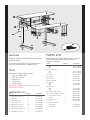
PARTS LIST
Before beginning assembly of your Elevate II Adjusta,
please review the parts list to verify that your
shipment is complete.
3
Product Quantity Part Number
01 Monitor Surface 1
48w 101-1112-03-00
60w 101-1110-03-00
02 Keyboard Surface 1
48w 101-1113-03-00
60w 101-1111-03-00
03 Gusset X 1 225-4611-00
04 Gusset Y 1 225-4612-00
05 Electric Leg 2 575-5085-00
06 Motor Housing 2 225-4613-00
07 Cross Pan 1
48w 225-4619-00
60w 225-4615-00
08 Cable Tray 1
48w 225-4638-00
60w 225-4637-00
09 Control Box (not shown) 1 400-5506-00
10 Control Box Cord (not shown) 2 400-5182-00
11 Power Cord (not shown) 1 400-5181-00
12 Key Pad 1 400-5357-00
13 Key Pad Slider 1 400-5358-00
14 Foot 2 835-5581-00
15 Adjusta Mechanism 1
for 48w Table 225-5546-00
for 60w Table 575-5072-00
Product Quantity Part Number
16 1/2" Button-head Screw 7 325-5193-00
17 Nylock Nut 7 325-5186-00
18 M6-20 Cap Screw 8 325-5272-00
19 3/4" Phillips Screw 4 325-5370-00
20 3/4" Button-head Screw 56 325-5575-00
21 M6x14 Flat-head Screw 4 325-5435-00
22 M6-10 Button-head Screw 8 325-5503-00
23 Wire Mgmt Snap-in Clip 2 175-5188-00
WELCOME
Thank you for purchasing Anthro's Elevate II Adjusta
electric lift table!
If you have any questions or if we can help you in
any way, please contact us at 800.325.3841.
TOOLS
Your Elevate II comes with these tools:
• 5/32" hex Anthro driver
• 5/32" hex driver bit
• 5mm hex key
• 1/8" hex key
• 3-way wrench
To make the assembly even easier, use your own
3/8" socket for Step 4.
HARDWARE LIST
01
02
03
04
05
06
07
08
12
13
14
15

4
Questions? Call us at 800.325.3841 or visit anthro.com. We’re happy to walk you through the assembly!
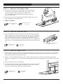
STEP 1 - ATTACH GUSSETS TO TOP
Lay the top surface upside down on a cushioned, non-marring surface. Locate
the front edge of the table. On Plus tables, the front of the table has a sloping
waterfall edge. On the Basic tables, the back edge of the table has the seam
where the edgebanding meets.
Align the Leg Gussets with the holes on the top so the upright flange faces the
outside of the table and the tapering end points to the front of the table.
Attach each gusset to the top with six 3/4" MDF Screws using the Anthro driver.
Front
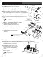
STEP 2 - INSTALL LEGS
Align one Leg with one Leg Gusset so the cord feeds out of the Leg
toward the center of the table. The Leg will rest on top of the Gusset's
button-head screws, so it may feel a little wobbly. [A]
Slide a Leg Housing over the Leg and down until it covers the Leg
Motor and the six screw holes on the housing line up with the six pre-
drilled holes on the shelf. [B]
Move to the front of the table and attach the front of the Housing to
the Leg with two M6-10MM Button Hd Screws (325-5503-00) using
the Anthro driver. Tilt the leg slightly to align the holes. [C]
Loosely attach the Housing to the shelf with six 3/4" Button Hd PB
Screws (325-5575-00). [D]
Attach the side of the Leg to the Leg Gusset with two M6-14 Flat-head
Screws (325-5435-00). [E]
Repeat for the other Leg and Housing.
A
B
M6-10 Button-head Screw
325-5503-00
C
D
M6x14 Flat Hd Screw
325-5435-00
E
3/4" Button Hd PB Screw
325-5575-00
3/4" Button Hd PB Screw
325-5575-00

Elevate II Adjusta Assembly Instructions
5
STEP 3 - INSTALL THE CROSS PAN
Align the Cross Pan with the Leg Assemblies so the pair of flanges
on the pan line up with the pre-drilled holes on the table. Attach
the back of the pan to the top with four 3/4" MDF Screws
(325-5575-00) and attach the front of the pan to the top with
three 3/4" MDF Screws.
Attach the pan to each leg housing with two M6x14 Button-head Screw
(325-5503-00) using the Anthro driver.
Tighten all fasteners.
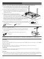
STEP 4 - INSTALL CONTROL BOX
Align the Control Box with the Cable Tray so the ports face up and the holes
on the Control Box line up with the holes on the Cable Tray. The Control Box
installs at the center of the tray on the 48w table. The 60w table comes with
three installation points (left, center, and right). Attach the box to the tray
with four 1/2" Button-head Screws and four Nylock Nuts using your own 3/8"
socket (or the 3-way wrench provided) and the smallest hex key (1/8") in your
kit.
1/2”Button-hd Screw
325-5193-00
Nylock Nuts
325-5186-00
Attaching the Control Box to the Cable Tray
of a shallow 48" wide table.
1/2” Flat-head Screw
325-5193-00
Nylock Nuts
325-5186-00
M6-10 Button-head Screw
325-5503-00
3/4" Button Hd PB Screw
325-5575-00
STEP 5 - INSTALL CABLE TRAY
Align the Cable Tray with the back of the table so the holes on the threaded posts on the cross pan line up with the holes
on the cable tray. Attach the tray to the pan with three Nylock Nuts using your own 3/8" socket or the 3-way wrench
provided. (The plastic end of the nut faces up.)
Connect a 1-meter Control Box Cable to each leg cable, then plug each into a port on the Control Box through the
opening in the support pan. Feed extra cable length through an opening in the support pan so it's organized in the Cable
Tray.
Plug the Power Cord into the Control Box.
Use the provided cable clips to route and organize cords. Install one cable clip
next to the Leg Gusset for the Keypad Cord (Installed in Step 8). Install the
other clip next to the Cross Pan for the Control Box Cables.

STEP 6A - ASSEMBLE ADJUSTA MECHANISM
Your Adjusta mechanism comes unassembled and
is boxed separately inside the package. Locate the
small bag of hardware included with the Adjusta
Mechanism. It includes (1) Post, (1) Cotter Pin, (2) Hex
Nuts, (2) Wood Screws, and (2) Cable Mounts.
Begin to assemble the mechanism by first locating the Crossbar and Brake/
Paddle assembly and position them as shown at right. Depress the Paddle once
to free the Brake Shaft.
Place the Brake Shaft between the two center Crossbar flanges. Insert the Post
through both center Crossbar flanges and the Brake Shaft.
Install the Cotter Pin through the single opening of the post to secure it in
place.
6
Questions? Call us at 800.325.3841 or visit anthro.com. We’re happy to walk you through the assembly!
STEP 7 - ATTACH ADJUSTA MECHANISM TO MONITOR SURFACE
Loosely attach the second Mechanism Arm
to the Monitor Surface using a total of six
3/4" Button-head Screws.
Align the brake assembly with the six holes
on the Monitor Surface. It may be necessary
to depress the paddle in order to position
the brake.
Secure the brake assembly with six 3/4"
Button-head Screws.
Mechanism Arm
Mechanism Arm
3/4" Button Hd PB Screw
325-5575-00
Cotter Pin
(included with 225-5548-00)
Cotter Pin
Post
Center Crossbar
Flanges
Brake
Shaft
Crossbar
Post
(included with
225-5548-00)
Brake/Paddle Assembly
Brake Cable
DETAIL VIEW
Arm Mechanism
Threaded
Bolts
5
/
16
" Hex
Nut
Paddle
Brake/Paddle
Assembly
Arm Mechanism
Crossbar
Lower Crossbar
‘Button’
NOTE: it is very important that you attach the Crossbar
ONLY to the Lower Crossbar Button.
STEP 6B - ASSEMBLE ADJUSTA ARMS
Unpack the remaining Adjusta mechanism
components and arrange them as shown at right.
Place one Crossbar End onto the lower Crossbar
Button and Threaded Bolt located on each Arm
Mechanism. Secure the Crossbar to the Arm
Mechanism using one 5/16" Hex Nut onto the
Threaded Bolt.
Repeat for remaining Crossbar End and Arm
Mechanism.
3/4" Button Hd PB Screw
325-5575-00

Elevate II Adjusta Assembly Instructions
7
M6-20 Cap Screw
325-5272-00
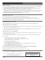
STEP 9 - INSTALL FEET
Align one foot with each leg so the wheels are at the back. Attach the foot to
the leg with four M6x20 Socket-head Screws using the Anthro driver. Repeat
for the other foot.
With the help of another person, carefully rotate the table onto its feet.
STEP 8 - ATTACH ADJUSTA MECHANISM TO KEYBOARD SURFACE
Slide the Keyboard Surface under the mechanism arms. Align the three holes
on each end of the Keyboard surface with the three holes on each mechanism
arm. Secure the arms to the Keyboard Surface with six 1" Button-head Screws.
Position the Paddle on the Keyboard Surface so the four holes on the Paddle
align with the four holes on the Keyboard Surface and the brake cable runs
under the Adjusta Bar. Secure the Paddle to the Keyboard Surface with four
3/4" Button-head Screws.
The keypad can be installed on the left or the right.
Choose a location, just remember that the table's upside
down now, so when you flip the table over, the keypad
will be on the opposite side. Align the keypad and its housing
with the four pre-drilled holes at the front of the keyboard surface so the
buttons are face-down at the front edge of the keyboard surface and the flat
side of the housing is against the shelf. Using four Phillips Head Screws, attach
the keypad and its housing to the front of the worksurface.
Route the Keypad's cable back to the Cross Pan and plug it into the Control Box.
Feed extra cable length through an opening in the support pan so it's organized
in the Cable Tray.
3/4” Phillips Screw
325-5370-00
Keypad and Slider
CONGRATULATIONS! YOUR ELEVATE II ADJUSTA ASSEMBLY IS COMPLETE!
RATINGS
Electrical Rating
Voltage rating: 120Vac, 60 Hz. When desk is moving with rated load: 400W. When desk is not moving: less than 100mW.
Temperature Ratings
Ambient temperature: 41 degrees F to 140 degrees F. Storage temperature: -4 degrees F to 158 degrees F.
Acclimate table to ambient temperature before use.
Load Rating
Elevate II Adjusta has a weight capacity of 150 lbs of distributed load on the back monitor surface and 40 lbs of
distributed load on the front keyboard surface.
Duty Cycle
Elevate II Adjusta has a 10% duty cycle. This provides 6 minutes of movement per hour or two minutes of continuous use
at full load. Once the table reaches its duty cycle, the table shuts down to cool; this usually takes about 20 minutes. Duty
cycle is reduced when the load exceeds approved weight limit or temperature is outside the stated range.
3/4" Button Hd PB Screw
325-5575-00

8
Warranty:
For warranty information, please visit: www.anthro.com/support/warranty
Notices:
Anthro logo is a registered trademark of Ergotron, Inc. © 1994 - 2016; Anthro-DNA is a
trademark of Ergotron Inc., © 2016. All rights reserved.
Anthro is also a brand of Ergotron Inc., a Nortek company.
Anthro reserves the right to modify the design and specifications without prior notice.
TROUBLESHOOTING GUIDE
Is the table giving you trouble? Try these steps first. Still need help? Contact Anthro at 800.325.3841.
Table won't go up, but it will go down.
Inspect the leg cables, control box cable, and power cable to be sure they are connected properly and not damaged. Need
replacements? Contact Anthro at 800.325.3841.
Lower the table to its lowest position, release the button, the press the DOWN button again for 5 seconds to home the
legs. The table will bump a few times, then rest.
Table won't move at all: no up, no down.
Has the table exceeded its duty cycle, moving more than 6 minutes per hour or 2 minutes continuously? If so, rest the
table for 20 minutes and try again.
Inspect the leg cables, control box cable, and power cable to be sure they are connected properly and not damaged.
Test the cables:
• Unplug the Leg Cable that is plugged into Port 1 of the control box.
• Push the DOWN button for 3 seconds and then the UP button for 3 seconds.
• Unplug the Power Cord from the Control Box.
• Plug the Leg Cable back into Port 1.
• Plug the Power Cord back into the Control Box.
• Push the DOWN button and hold until the table reaches its lowest position and stops, then release.
• Push the DOWN button again and hold for 5 seconds.
• Push the UP button to verify the that the table goes up.
Desk will only go up a few inches...then stop...then up another few inches...then stop again.
Verify that the load on the table does not exceed its 150 lbs lift capacity.
Cleaning instructions? Clean the table with a mild detergent and a soft cloth.
*300-5582-00*
300-5582-00
SAFETY CHECK
Plug in the table and home the legs. To home the legs, move the table to its lowest position, release the DOWN button,
then press and hold the DOWN button for 5 seconds. The table will bump a few times, then rest.
Raise the table to its highest position. Watch all the cords and cables as the table moves to verify that cords aren't
wrapped around anything and that nothing interferes with the movement of the table.
Every time you add equipment onto the table, route cords into the cable tray. Carefully move the table through its entire
range of motion to be sure that your power and data cables are long enough. Check the area around your table for
obstructions below, beside, and above the table to be sure there are no collisions.
Verify that the load is distributed evenly across the table.
MOVING THE TABLE
Keep your equipment safe: remove equipment from the table before you move it.
Before moving the table, lower the table all the way down and raise the keyboard surface all the way up.
To move the table, lift the front keyboard surface enough to get the front feet off the ground, and roll it into place.
Lift (don't roll) the table over thresholds, transitions, or bumps.
-
 1
1
-
 2
2
-
 3
3
-
 4
4
-
 5
5
-
 6
6
-
 7
7
-
 8
8


Anthro Elevate II Adjusta Assembly Instructions Manual
- Catégorie
- Bureaux d'ordinateur
- Taper
- Assembly Instructions Manual
dans d''autres langues
- English: Anthro Elevate II Adjusta
Autres documents
-
Victor DC300 Le manuel du propriétaire
-
Ergotron MVBD48SSBK Assembly Instructions
-
-
Herman Miller Motia Sit-to-Stand Tables Product Instructions
-
-
Ergotron 24-271-928 Manuel utilisateur
-
ROOMS TO GO 37851501 Assembly Instructions
-
-
Humanscale eFloat Go 2.0 Installation & Maintenance Instructions
-
CYBEX V Series Assembly Instructions Manual