
OWNER’S MANUAL
FRENCH DOOR
REFRIGERATOR
Please read this owner's manual thoroughly before
operating and keep it handy for reference at all times.
ENGLISH
FRANÇAIS
ESPAÑOL
MFL68680439
Rev.03_170117
Copyright © 2015 - 2017 LG Electronics Inc. All Rights Reserved.
www.lg.com

2
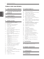
TABLE OF CONTENTS
ENGLISH
TABLE OF CONTENTS
3 PRODUCT FEATURES
4
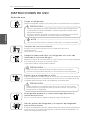
IMPORTANT SAFETY
INSTRUCTIONS
7 COMPONENTS
7 Refrigerator Exterior
8 Refrigerator Interior
9 INSTALLATION
9 Installation Overview
10 Specifications
11 Unpacking Your Refrigerator
11 Choosing the Proper Location
11 - Flooring
12 - Ambient Temperature
12 - Measuring the Clearances
12 Removing/Assembling the Refrigerator
Door Handles
13 Removing/Assembling the Freezer
Drawer Handle
13 Removing/Assembling the Doors and
Drawers
13 - Removing the Left Refrigerator Door
14 - Removing the Right Refrigerator Door
15 - Assembling the Right Refrigerator Door
15 - Assembling the Left Refrigerator Door
16 - Removing the Freezer Drawers
17 - Assembling the Freezer Drawers
19 Connecting the Water Line
19 - Before You Begin
19 - Water Pressure
19 - What You Will Need
20 - Water Line Installation Instructions
22 Turning On the Power
23 Leveling and Door Alignment
23 - Leveling
23 - Door Alignment
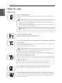
24 HOW TO USE
24 Before Use
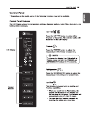
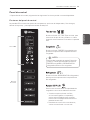
25 Control Panel
25 - Control Panel Features
27 In-Door Ice Bin
27 - Detaching the In-Door Ice Bin
27 - Assembling the In-Door Ice Bin
28 Automatic Icemaker
28 - Automatic Icemaker (Ice Room)
28 - Automatic Icemaker (Freezer Room)
28 - Turning the Automatic Icemaker On or Off
29 - When You Should Turn the Icemaker Off
29 - Normal Sounds You May Hear
29 - Preparing for Vacation
30 Ice and Water Dispenser
30 - Dispenser
30 - Using the Dispenser
30 - Locking the Dispenser
30 - Cleaning the Dispenser Stand
31 Storing Food
31 - Food Preservation Location
32 - Food Storage Tips
32 - Storing Frozen Food
33 Humidity Controlled Crisper
34 Detaching and Assembling the Storage Bins
36 Adjusting the Refrigerator Shelves
37 MAINTENANCE
37 Cleaning
38 Replacing the Water Filter
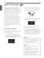
40 SMART DIAGNOSIS
40 Using Smart Diagnosis
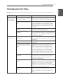
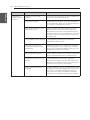
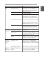
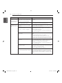
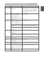
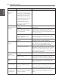
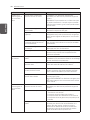
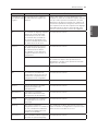
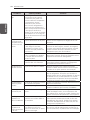
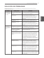
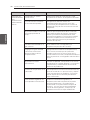
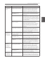
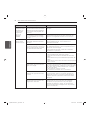
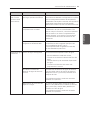
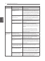
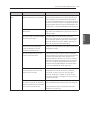
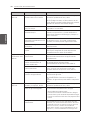
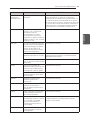
41 TROUBLESHOOTING
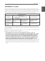
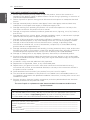
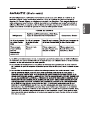
51 WARRANTY

3
PRODUCT FEATURES
ENGLISH
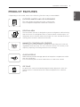
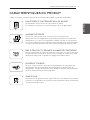
PRODUCT FEATURES
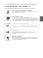
* Depending on the model, some of the following functions may not be available.
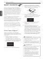
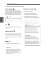
FILTERED WATER AND ICE DISPENSER
The water dispenser dispenses fresh, chilled water.
The ice dispenser dispenses cubed and crushed ice.
DOOR ALARM
The Door Alarm function is designed to prevent refrigerator malfunctioning
that could occur if a refrigerator door or freezer drawer remains open. If a
refrigerator door or freezer drawer is left open for more than 60 seconds, a
warning alarm sounds in 30 second intervals.
HUMIDITY CONTROLLED CRISPER
The Humidity Controlled Crisper is designed to help keep your fruits and
vegetables fresh and crisp. You can control the amount of humidity in the
crisper by adjusting the setting between Low and High.
GLIDE‘N’SERVE
Glide`N’Serve provides storage space that keeps the compartment colder
than the refrigerator.
It is a convenient place to store sandwiches or meat to be cooked.
ICE PLUS
Ice production can be increased by approximately 20 percent when the
freezer section is maintained at the coldest temperature for a 24-hour
period.

:This product contains chemicals known to the State of California
to cause cancer and birth defects or other reproductive harm.Wash hands after handling.


7
COMPONENTS
ENGLISH
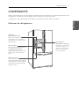
COMPONENTS
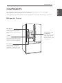
Use this page to become more familiar with the parts and features of your refrigerator.
Page references are included for your convenience.
*The appearance and specifications of the actual product may differ depending on the model.
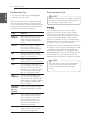
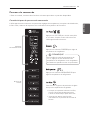
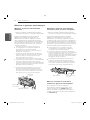
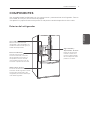
Refrigerator Exterior
LED Display
Displays the refrigerator and
freezer temperature, the water
filter condition and the dispenser
status.
Ice Plus
When this feature is activated,
the freezer section will run at the
coldest temperature for a 24-hour
period to increase ice production.
Door Alarm
A warning alarm sounds at 30-
second intervals when the
refrigerator or freezer door is left
open for more than 60 seconds.
Filtered Water and
Ice Dispenser
Dispenses fresh, chilled,
filtered water through
the door. The ice
dispenser offers cubed
or crushed ice.

8
COMPONENTS
ENGLISH
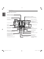
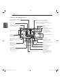
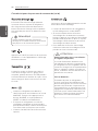
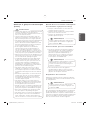
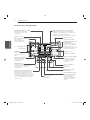
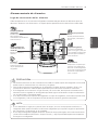
Refrigerator Interior
Modular Door Bins
Dairy Product Bin
Pullout Drawer
LED Interior Lamps
The interior lamps light up the
inside of the refrigerator.
Refrigerator Shelves
The shelves in your
refrigerator are
adjustable to meet your
individual storage needs.
Durabase Divider
Durabase
Automatic Icemaker
Removable Ice
Storage Bin
The ice storage bin
can be removed to fill
ice buckets, coolers,
or pitchers.
Fixed Door Bins
Can Storage Bin
Used to preserve chilled
food or drinks.
Water Filter
Mullion
Folds in when the
left door is opened.
SpacePlus Ice System
Ice cubes are
automatically produced.
Auto Closing Hinge
The refrigerator doors
and freezer drawers close
automatically when you push
them slightly.
(The door only closes
automatically when it is open
at an angle of less than 30°.)
Crispers
Controls humidity and
helps vegetables and
fruit to stay crisp.
Glide’N’Serve
Allows you to store food items
at a different temperature than
the regular refrigerator area.
Smart Diagnosis Speaker
Hold your phone to this speaker when
activating Smart Diagnosis. Refer to the
Smart Diagnosis section for more details.
1_MFL62184517_Eng.indd 81_MFL62184517_Eng.indd 8 2012.6.28 4:0:40 PM2012.6.28 4:0:40 PM

9
INSTALLATION
ENGLISH
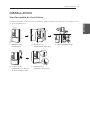
INSTALLATION
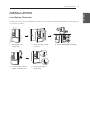
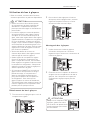
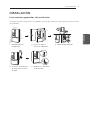
Installation Overview
Please read the following installation instructions first after purchasing this product or transporting
it to another location.
1 Unpacking your
refrigerator
2 Choosing the proper
location
3 Disassembling/Assembling
4 Connecting the water
supply and water line
5 Leveling and Door
Alignment

10
INSTALLATION
ENGLISH
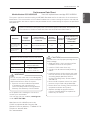
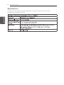
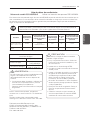
Specifications
The appearance and specifications listed in this manual may vary due to constant product
improvements.
Bottom-freezer refrigerator model LFX25973*
Description French door refrigerator
Electrical requirements 115 VAC @ 60 Hz
Min. / Max. Water pressure
Dimensions 35 3/4” (W) X 34 1/4” (D) X 69 3/4” (H), 46 1/2” (D w/ door open)
908 mm (W) X 869.95 mm (D) X 1 771.65 (H), 1 181.1 mm (D w/ door
open)
Net weight
309 lb. (140kg)
20 and 120 psi (140 and 830 kPa)

11
INSTALLATION
ENGLISH
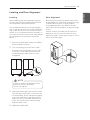
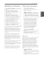
Choosing the Proper Location
Select a place where a water supply can
be easily connected for the automatic
icemaker.
Unpacking Your Refrigerator
WARNING
Use two or more people to move and
install the refrigerator. Failure to do so
can result in back or other injury.
Your refrigerator is heavy. When moving
the refrigerator for cleaning or service,
be sure to protect the floor. Always pull
the refrigerator straight out when moving
it. Do not wiggle or walk the refrigerator
when trying to move it, as floor damage
could occur.
Keep flammable materials and vapors,
such as gasoline, away from the
refrigerator. Failure to do so can result in
fire, explosion, or death.
Remove tape and any temporary labels from your
refrigerator before using. Do not remove any
warning-type labels, the model and serial number
label, or the Tech Sheet that is located under the
front of the refrigerator.
To remove any remaining tape or glue, rub the
area briskly with your thumb. Tape or glue residue
can also be easily removed by rubbing a small
amount of liquid dish soap over the adhesive with
your fingers. Wipe with warm water and dry.
Do not use sharp instruments, rubbing alcohol,
flammable fluids, or abrasive cleaners to remove
tape or glue. These products can damage the
surface of your refrigerator.
Refrigerator shelves are installed in the shipping
position. Please reinstall shelves according to
your individual storage needs.
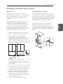
Flooring
To avoid noise and vibration, the unit must be
leveled and installed on a solidly constructed
floor. If required, adjust the leveling legs to
compensate for unevenness of the floor. The
front should be slightly higher than the rear to
aid in door closing. Leveling legs can be turned
easily by tipping the cabinet slightly. Turn the
leveling legs to the left to raise the unit or to
the right to lower it. (See Leveling and door
AlIgnment.)
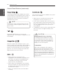
NOTE
Installing on carpeting, soft tile surfaces,
a platform or weakly supported structure
is not recommended.
The refrigerator should always be plugged
into its own individual properly grounded
electrical outlet rated for 115 Volts, 60 Hz,
AC only, and fused at 15 or 20 amperes.
This provides the best performance
and also prevents overloading house
wiring circuits which could cause a fire
hazard from overheated wires. It is
recommended that a separate circuit
serving only this appliance be provided.
WARNING
To reduce the risk of electric shock,
do not install the refrigerator in a wet or
damp area.
NOTE
The water pressure must be between
20 and 120 psi (140 and 830 kPa) on
models without a water filter and
between 40 and120 psi (280 and 830kPa)
on models with a water filter.

12
INSTALLATION
ENGLISH
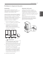
Ambient Temperature
Install this appliance in an area where the
temperature is between 55°F (13°C) and 110°F
(43°C). If the temperature around the appliance
is too low or high, cooling ability may be
adversely affected.
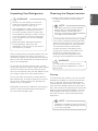
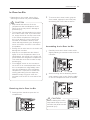
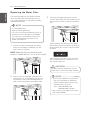
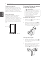
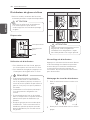
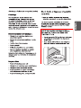
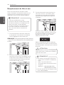
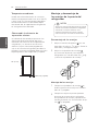
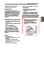
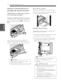
Measuring the Clearances
Too small of a distance from adjacent items
may result in lowered freezing capability and
increased electricity consumption charges.
Allow at least 24 inches (61 cm) in front of the
refrigerator to open the doors, and at least
2 inches (5.08 cm) between the back of the
refrigerator and the wall.
2” (5.08 cm)
24” (61 cm)
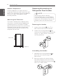
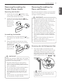
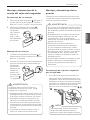
Removing/Assembling the
Refrigerator Door Handles
Removing the Handles
1
Loosen the set screws with a
3
/
32
in.
Allen wrench and remove the handle.
2
Loosen the mounting fasteners that
connect to the refrigerator door and handle
using a
1
/
4
in. Allen wrench, remove the
mounting fasteners.
Assembling the Handles
1
Assemble the mounting fasteners at
both ends of the handle using a
1
/
4
in.
Allen wrench.
2
Place the handle on the door by fitting
the handle footprints over the mounting
fasteners and tightening the set screws
with a
3
/
32
in. Allen wrench.
NOTE
Removing the doors is always
recommended when it is necessary to
move the refrigerator through a narrow
opening. If it is necessary to remove the
handles, follow the directions below.

13
INSTALLATION
ENGLISH
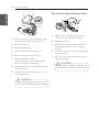
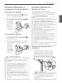
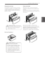
Removing/Assembling the
Freezer Drawer Handle
Removing the Handles
1
Loosen the set screws located on the
lower side of the handle with a
1
/
8
in. Allen
wrench and remove the handle.
2
Loosen the mounting fasteners that
connect to the freezer drawer and handle
using a
1
/
4
in.
Allen wrench,
and remove
the mounting
fasteners.
Assembling the Handles
1
Assemble the mounting fasteners at
both ends of the handle using a
1
/
4
in. Allen
wrench.
2
Place the handle on the door by fitting
the handle footprints over the mounting
fasteners and
tightening the
set screws
with a
1
/
8
in.
Allen wrench.
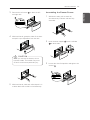
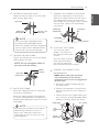
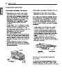
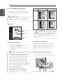
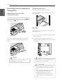
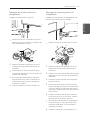
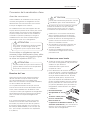
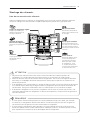
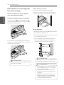
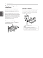
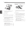
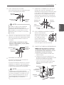
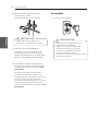
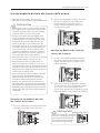
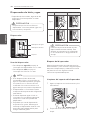
Removing the Left Refrigerator Door
1
The water supply is connected to the
upper right part of the rear surface of the
refrigerator. Remove the ring in the joint
area. Hold the water supply connection
and gently push the Collet to detach the
water supply line as shown , and .
NOTE
Detachment of the water supply line is
applicable only when detaching the left
refrigerator door.
WARNING
If your entrance door is too narrow for the
y
refrigerator to pass through, remove the
refrigerator doors and move the refrigerator
sideways through the doorway.
Use two or more people to remove and
y
install the refrigerator doors. Failure to do
so can result in back or other injury.
Disconnect the electrical supply to the
y
refrigerator before installing. Failure to do
so could result in serious injury or death.
Do not put hands, feet or other objects into
y
the air vents or bottom of the refrigerator.
You may be injured or receive an electrical
shock.
Be careful when handling the hinge and
y
stopper. It may result in injury.
Remove food and bins from the doors and
y
drawers before detaching.
Collet
Removing/Assembling the
Doors and Drawers
Removing the doors is always recommended
when it is necessary to move the refrigerator
through a narrow opening.
WARNING
When the customer takes apart the handle
or assemble it from a refrigerator, please be
cautious of following things.
Hold the handle with your own hand to
y
make sure not to drop the handle to the
floor or instep while taking apart the handle
from a refrigerator.
Do not swing the handle towards people or
y
animals after taking apart the handle.
Insert the bracket hole of the handle into
y
the stopper bolt of the door exactly, and
then assemble the set screws to fix the
handle.
Check if there’s any gap between the door
y
and handle after fixing the handle.

14
INSTALLATION
ENGLISH
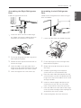
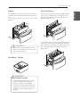
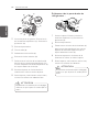
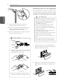
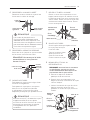
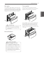
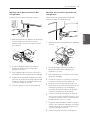
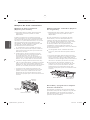
2
Open the left door. Remove the top hinge
cover screw (1). Lift up the cover (2).
3
Remove the cover.
4
Pull out the tube (3).
5
Disconnect all wire harnesses (4).
6
Remove the grounding screw (5).
7
Rotate the hinge lever (6)
counterclockwise. Lift the top hinge (7)
free of the hinge lever latch (8).
8
Lift the door from the middle hinge pin and
remove the door.
9
Place the door, inside facing up, on a non-
scratching surface.
CAUTION
When lifting the hinge free of the latch, be
careful that the door does not fall forward.
CAUTION
When lifting the hinge free of the latch, be
careful that the door does not fall forward.
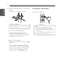
Removing the Right Refrigerator Door
1
Open the door. Remove the top hinge
cover screw (1). Lift up the cover (2).
2
Remove the cover.
3
Rotate the hinge lever (3) clockwise. Lift
the top hinge (4) free of the hinge lever
latch (5).
4
Lift the door from the middle hinge pin and
remove the door.
5
Place the door, inside facing up, on a non-
scratching surface.
(1)
(2)
(4)
(3)
(6)
(7)
(8)
(5)
(2)
(3)
(4)
(5)
(1)

15
INSTALLATION
ENGLISH
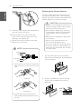
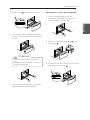
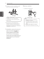
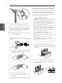
1
Lower the door onto the middle hinge pin.
2
Fit the top hinge (7) over the hinge lever
latch (8) and into place.
3
Rotate the lever (6) clockwise to secure
the hinge.
4
Install the grounding screws (5) and
connect the two wire harnesses (4).
5
Push the water tube (3) located at the top
of the left door into the hole beside the left
hinge on the top of the cabinet until it exits
through the back.
6
Insert the water supply tube (3) into the
connector until you see only one scale
mark. Fully insert the tub cover (15 mm).
7
Hook the tabs on the left side of the hinge
cover (1) under the edge of the top hinge (7)
and position the cover in place.
8
Insert and tighten the cover screw (1).
1
Lower the door onto the middle hinge
pin. Make sure that the plastic sleeve is
inserted into the bottom of the door.
2
Fit the top hinge (4) over the hinge lever
latch (5) and into place.
3
Rotate the lever (3) counterclockwise to
secure the hinge.
4
Hook the tabs on the right side of the
hinge cover (2) under the edge of the top
hinge (4) and position the cover in place.
5
Insert and tighten the cover screw (1).
Install the right-side door first.
Assembling the Right Refrigerator
Door
Assembling the Left Refrigerator
Door
Install the left refrigerator door after the right
door is installed.
(2)
(1)
(3)
(4)
(5)
(6)
(7)
(8)
(2)
(3)
(4)
(5)
(1)

16
INSTALLATION
ENGLISH
CAUTION
Use two or more people to remove and
y
install the freezer drawer. Failure to do so
can result in back or other injury.
Do not hold the handle when removing
y
or replacing the drawer. The handle may
come off and it could cause personal
injury.
Be careful of sharp hinges on both sides
y
of the drawer.
When you lay the drawer down, be
y
careful not to damage the floor.
Do not sit or stand on the freezer drawer.
y
To prevent accidents, keep children and
y
pets away from the drawer. Do not leave
the drawer open.
NOTE
1) Gently press the Collet and insert the
tube until only one line shows on the
tube.
(Correct)
(Incorrect)
2) Pull the tube to make sure that the
tube is tightly fastened and then insert
the clip.
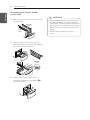
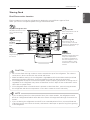
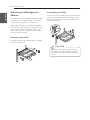
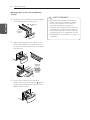
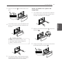
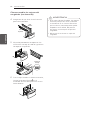
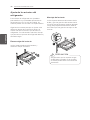
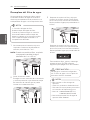
Removing the Freezer Drawers
The top, middle and bottom drawers are all
removed in the same way. In the following
figures, the Pullout Drawer located above the
freezer drawer is not shown for clarity.
1
Pull the drawer open to full extension.
Remove the lower basket by lifting basket
from rail system.
2
Press in the tabs on the rail covers and
lift them up to separate from the rail
assembly.
Collet
Tube
Insert Line
Clip
9
Insert the water supply tube at least 5/8 in.
(15 mm) into the connector.
10
Hook the tab on the door switch side
of the cover under the edge of the wire
opening in the cabinet top.
11
Position the cover into place. Insert and
tighten the cover screw.
1

17
INSTALLATION
ENGLISH
2
1
3
Lower door into final position and tighten the
screws
3
.
3
Assembling the Freezer Drawer
1
With both hands, pull out each rail
simultaneously until both rails are fully
extended.
2
Hook the door support
1
into the rail tabs
2
on both sides.
3
Remove the rail screw
2
on both the left
and right rails.
4
With both hands, grasp the sides of the door
and pull it up to separate it from the rails.
5
With both hands, hold each rail and push it in
to allow both rails to slide in simultaneously.
CAUTION
When you remove the drawer, do not
hold the handle. The handle may come
off and it could cause personal injury.
2

18
INSTALLATION
ENGLISH
Assembling the Freezer Drawer
(continued)
4
Make sure you have the correct rail cover
for each side.
5
Align the tabs on the covers with the
assembly holes on each rail, and snap the
rail covers in place to secure.
6
With the drawer pulled out to full
extension, insert the lower basket
4
in
the rail assembly.
WARNING
If the Durabase divider is removed, there is
y
enough open space for children or pets to
crawl inside. To prevent accidental child and
pet entrapment or suffocation risk, DO NOT
allow them to touch or go near the freezer
drawer.
DO NOT step or sit down on freezer
y
drawer.
4
Right Rail
Cover
Left Rail
Cover
Assembly
Hole

19
INSTALLATION
ENGLISH
CAUTION
Wear eye protection during installation
to prevent injury.
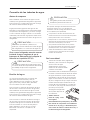
Connecting the Water Line
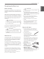
Before You Begin
This water line installation is not covered by the
refrigerator warranty. Follow these instructions
carefully to minimize the risk of expensive water
damage.
Water hammer (water banging in the pipes) in
house plumbing can cause damage to refrigerator
parts and can lead to water leakage or flooding.
Call a qualified plumber to correct water hammer
before installing the water supply line to the
refrigerator.
If you use your refrigerator before connecting
the water line, make sure the icemaker power
switch is in the OFF (O) position.
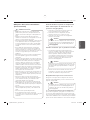
Water Pressure
A cold water supply. The water pressure must
be between 20 and 120 psi (140 and 830 kPa)
on models without a water filter and between
40 and 120 psi (280 and 830kPa) on models
with a water filter.
If a reverse osmosis water filtration system is
connected to your cold water supply, this water
line installation is not covered by the refrigerator
warranty. Follow the following instructions
carefully to minimize the risk of expensive water
damage.
If a reverse osmosis water filtration system is
connected to your cold water supply, the water
pressure to the reverse osmosis system needs
to be a minimum of 40 and 60 psi
( 280 and 420 kPa), less than 2.0~3.0 sec. to
fill a cup of 7 oz(200 cc) capacity.
If the water pressure from the reverse
osmosis system is less than 21 psi (145 kPa)
(takes more than 4.0 sec to fill a cup of 7 oz
(200 cc) capacity):
Check to see if the sediment filter in
the reverse osmosis system is blocked.
Replace the filter if necessary.
Allow the storage tank on the reverse
usage.
If the issue concerning water pressure
from reverse osmosis remains, call a
licensed, qualified plumber.
All installations must be in accordance
with local plumbing code requirements.
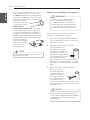
What You Will Need
Copper Tubing,
¼ in. outer diameter, to
connect the refrigerator to the water
supply. Be sure both ends of the tubing
are cut square.
To determine how
much tubing you need:
measure the distance
from the water valve on the back of the
refrigerator to the water supply pipe.
Then, add 8 feet
(2.4 m). Be sure there is sufficient extra
tubing (about 8 feet [2.4 m] coiled into 3
turns of about 10 in. [25 cm] diameter)
to allow the refrigerator to move out
from the wall after installation.
Power drill.
½ in. or adjustable
wrench.
Flat blade and Phillips
head screwdrivers.
Two ¼ in. outer
diameter compression
nuts and 2 ferrules (sleeves)
to connect the
copper tubing to the shutoff valve and
the refrigerator water valve.
CAUTION
Do not install the icemaker tubing in
areas where temperatures fall below
freezing.
CAUTION
To prevent burns and product damange,
only connect the refrigerator water line to
a cold water supply.

20
INSTALLATION
ENGLISH
NOTE
A self piercing saddle type water valve
should not be used.
NOTE
The hookup line cannot be white, plastic
tubing. Licensed plumbers must use
only copper tubing NDA tubing #49595
or 49599 or Cross Link Polyethylene
(PEX) tubing.
If your existing copper water line has a
y
flared fitting at the end, you will need
an
adapter
(available at plumbing supply
stores) to connect the water line to the
refrigerator OR you can cut off the flared
fitting with a tube
cutter and then use a
compression fitting.
Shutoff valve to
y
connect to the cold water line.
The shutoff
valve should have a water inlet with a
minimum inside diameter of 5/32 in. at
the point of connection to the COLD
WATER LINE. Saddle-type shutoff valves
are included in many water supply kits.
Before purchasing,
make sure a saddle-
type valve complies
with your local
plumbing codes.
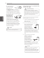
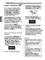
Water Line Installation Instructions
Install the shutoff valve on the nearest
frequently used drinking water line.
1
SHUT OFF THE MAIN WATER SUPPLY
Turn on the nearest faucet to relieve the
pressure on the line.
2
CHOOSE THE VALVE LOCATION
Choose a location for
the valve that is easily
accessible. It is best to
connect into the side of a
vertical water pipe. When
it is necessary to connect
into a horizontal water
pipe, make the connection to the top or
side, rather than at the bottom, to avoid
drawing off any sediment from the water
pipe.
3
DRILL THE HOLE FOR THE VALVE
Drill a ¼ in. hole in
the water pipe using
a sharp bit. Remove
any burrs resulting
from drilling the hole
in the pipe. Be careful
not to allow water
to drain into the drill. Failure to drill a ¼ in.
hole may result in reduced ice production
or smaller cubes.
WARNING
When using any electrical device
(such as a power drill) during
installation, be sure the device is
battery powered, double insulated
or grounded in a manner that will
prevent the hazard of electric shock.
La page est en cours de chargement...
La page est en cours de chargement...
La page est en cours de chargement...
La page est en cours de chargement...
La page est en cours de chargement...
La page est en cours de chargement...
La page est en cours de chargement...
La page est en cours de chargement...
La page est en cours de chargement...
La page est en cours de chargement...
La page est en cours de chargement...
La page est en cours de chargement...
La page est en cours de chargement...
La page est en cours de chargement...
La page est en cours de chargement...
La page est en cours de chargement...
La page est en cours de chargement...
La page est en cours de chargement...
La page est en cours de chargement...
La page est en cours de chargement...
La page est en cours de chargement...
La page est en cours de chargement...
La page est en cours de chargement...
La page est en cours de chargement...
La page est en cours de chargement...
La page est en cours de chargement...
La page est en cours de chargement...
La page est en cours de chargement...
La page est en cours de chargement...
La page est en cours de chargement...
La page est en cours de chargement...
La page est en cours de chargement...
La page est en cours de chargement...
La page est en cours de chargement...
La page est en cours de chargement...
La page est en cours de chargement...
La page est en cours de chargement...
La page est en cours de chargement...
La page est en cours de chargement...
La page est en cours de chargement...
La page est en cours de chargement...
La page est en cours de chargement...
La page est en cours de chargement...
La page est en cours de chargement...
La page est en cours de chargement...
La page est en cours de chargement...
La page est en cours de chargement...
La page est en cours de chargement...
La page est en cours de chargement...
La page est en cours de chargement...
La page est en cours de chargement...
La page est en cours de chargement...
La page est en cours de chargement...
La page est en cours de chargement...
La page est en cours de chargement...
La page est en cours de chargement...
La page est en cours de chargement...
La page est en cours de chargement...
La page est en cours de chargement...
La page est en cours de chargement...
La page est en cours de chargement...
La page est en cours de chargement...
La page est en cours de chargement...
La page est en cours de chargement...
La page est en cours de chargement...
La page est en cours de chargement...
La page est en cours de chargement...
La page est en cours de chargement...
La page est en cours de chargement...
La page est en cours de chargement...
La page est en cours de chargement...
La page est en cours de chargement...
La page est en cours de chargement...
La page est en cours de chargement...
La page est en cours de chargement...
La page est en cours de chargement...
La page est en cours de chargement...
La page est en cours de chargement...
La page est en cours de chargement...
La page est en cours de chargement...
La page est en cours de chargement...
La page est en cours de chargement...
La page est en cours de chargement...
La page est en cours de chargement...
La page est en cours de chargement...
La page est en cours de chargement...
La page est en cours de chargement...
La page est en cours de chargement...
La page est en cours de chargement...
La page est en cours de chargement...
La page est en cours de chargement...
La page est en cours de chargement...
La page est en cours de chargement...
La page est en cours de chargement...
La page est en cours de chargement...
La page est en cours de chargement...
La page est en cours de chargement...
La page est en cours de chargement...
La page est en cours de chargement...
La page est en cours de chargement...
La page est en cours de chargement...
La page est en cours de chargement...
La page est en cours de chargement...
La page est en cours de chargement...
La page est en cours de chargement...
La page est en cours de chargement...
La page est en cours de chargement...
La page est en cours de chargement...
La page est en cours de chargement...
La page est en cours de chargement...
La page est en cours de chargement...
La page est en cours de chargement...
La page est en cours de chargement...
La page est en cours de chargement...
La page est en cours de chargement...
La page est en cours de chargement...
La page est en cours de chargement...
La page est en cours de chargement...
La page est en cours de chargement...
La page est en cours de chargement...
La page est en cours de chargement...
La page est en cours de chargement...
La page est en cours de chargement...
La page est en cours de chargement...
La page est en cours de chargement...
La page est en cours de chargement...
La page est en cours de chargement...
La page est en cours de chargement...
La page est en cours de chargement...
La page est en cours de chargement...
La page est en cours de chargement...
La page est en cours de chargement...
La page est en cours de chargement...
La page est en cours de chargement...
La page est en cours de chargement...
La page est en cours de chargement...
La page est en cours de chargement...
La page est en cours de chargement...
La page est en cours de chargement...
La page est en cours de chargement...
La page est en cours de chargement...
La page est en cours de chargement...
La page est en cours de chargement...
La page est en cours de chargement...
La page est en cours de chargement...
La page est en cours de chargement...
La page est en cours de chargement...
La page est en cours de chargement...
-
 1
1
-
 2
2
-
 3
3
-
 4
4
-
 5
5
-
 6
6
-
 7
7
-
 8
8
-
 9
9
-
 10
10
-
 11
11
-
 12
12
-
 13
13
-
 14
14
-
 15
15
-
 16
16
-
 17
17
-
 18
18
-
 19
19
-
 20
20
-
 21
21
-
 22
22
-
 23
23
-
 24
24
-
 25
25
-
 26
26
-
 27
27
-
 28
28
-
 29
29
-
 30
30
-
 31
31
-
 32
32
-
 33
33
-
 34
34
-
 35
35
-
 36
36
-
 37
37
-
 38
38
-
 39
39
-
 40
40
-
 41
41
-
 42
42
-
 43
43
-
 44
44
-
 45
45
-
 46
46
-
 47
47
-
 48
48
-
 49
49
-
 50
50
-
 51
51
-
 52
52
-
 53
53
-
 54
54
-
 55
55
-
 56
56
-
 57
57
-
 58
58
-
 59
59
-
 60
60
-
 61
61
-
 62
62
-
 63
63
-
 64
64
-
 65
65
-
 66
66
-
 67
67
-
 68
68
-
 69
69
-
 70
70
-
 71
71
-
 72
72
-
 73
73
-
 74
74
-
 75
75
-
 76
76
-
 77
77
-
 78
78
-
 79
79
-
 80
80
-
 81
81
-
 82
82
-
 83
83
-
 84
84
-
 85
85
-
 86
86
-
 87
87
-
 88
88
-
 89
89
-
 90
90
-
 91
91
-
 92
92
-
 93
93
-
 94
94
-
 95
95
-
 96
96
-
 97
97
-
 98
98
-
 99
99
-
 100
100
-
 101
101
-
 102
102
-
 103
103
-
 104
104
-
 105
105
-
 106
106
-
 107
107
-
 108
108
-
 109
109
-
 110
110
-
 111
111
-
 112
112
-
 113
113
-
 114
114
-
 115
115
-
 116
116
-
 117
117
-
 118
118
-
 119
119
-
 120
120
-
 121
121
-
 122
122
-
 123
123
-
 124
124
-
 125
125
-
 126
126
-
 127
127
-
 128
128
-
 129
129
-
 130
130
-
 131
131
-
 132
132
-
 133
133
-
 134
134
-
 135
135
-
 136
136
-
 137
137
-
 138
138
-
 139
139
-
 140
140
-
 141
141
-
 142
142
-
 143
143
-
 144
144
-
 145
145
-
 146
146
-
 147
147
-
 148
148
-
 149
149
-
 150
150
-
 151
151
-
 152
152
-
 153
153
-
 154
154
-
 155
155
-
 156
156
-
 157
157
-
 158
158
-
 159
159
-
 160
160
-
 161
161
-
 162
162
-
 163
163
-
 164
164
-
 165
165
-
 166
166
-
 167
167
-
 168
168


dans d''autres langues
- English: LG LFX25973D User guide
- español: LG LFX25973D Guía del usuario
Documents connexes
Autres documents
-
LG Electronics LFX25973ST Mode d'emploi
-
 Kenmore Elite 73165 Le manuel du propriétaire
-
Kenmore Elite 24 cu. ft. Counter-Depth Bottom-Freezer Refrigerator w/ Grab-N-Go Door ENERGY STAR Le manuel du propriétaire
-
LG Electronics LFX25974SW Mode d'emploi
-
-
 Kenmore Elite 73157 Le manuel du propriétaire
-
-
LG Electronics LFXS32726S Manuel utilisateur
-

