
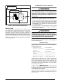
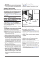
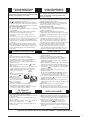
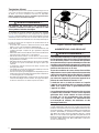
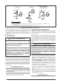
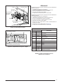
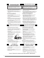
R7TQ- 072 / 090 / 120 Series
Single Package Gas Heating / Electric Cooling Rooftop Units
R7TQ Series Shown with optional electrical disconnect switch and convenience outlet
INSTALLATION INSTRUCTIONS
WARNING
FIRE OR EXPLOSION HAZARD
WHAT TO DO IF YOU SMELL GAS

2
TABLE OF CONTENTS
IMPORTANT SAFETY INFORMATION3
3
GENERAL INFORMATION4
About the Rooftop Unit ..................................................... 4
Before You Install this Equipment .................................... 4
Locating the Unit .............................................................. 4
Heating Load .................................................................... 5
5
Vent Termination .............................................................. 6
CIRCULATING AIR SUPPLY6
Unconditioned Spaces ..................................................... 7
Acoustical Ductwork ......................................................... 7
Air Filter Requirements .................................................... 7
UNIT INSTALLATION7
Packaging Removal ......................................................... 7
Rigging & Hoisting ........................................................... 7
Minimum Clearance Requirements .................................. 8
Vertical to Horizontal Conversion ..................................... 8
Rooftop Mounting ............................................................. 8
Ground Level ................................................................... 8
Condensate Drain ............................................................ 9
9
Leak Check ...................................................................... 10
High Altitude Deration ...................................................... 10
Conversion to LP/Propane ............................................... 11
ELECTRICAL WIRING11
Pre-Electrical Checklist .................................................... 11
Line Voltage ..................................................................... 11
Grounding ........................................................................ 12
Unbalanced 3-Phase Supply Voltage .............................. 12
Thermostat / Low Voltage Connections ........................... 12
Heat Anticipator ............................................................... 12
Blower Speed ................................................................... 12
13
Pre-Start Check List ........................................................ 13
Startup Procedures .......................................................... 13
Air Circulation ................................................................... 14
System Cooling ................................................................ 14
System Heating ................................................................ 14
Verifying & Adjusting Temperature Rise .......................... 14
Verifying Burner Operation .............................................. 14
Verifying Operation of Over-Temperature Limit Control .. 14
Verifying & Adjusting Firing Rate ..................................... 15
Manifold Pressure Adjustment ......................................... 15
Refrigerant Charging ........................................................ 15
OPERATING SEQUENCE16
Cooling Mode ................................................................... 16
Heating Mode ................................................................... 16
Blower Mode .................................................................... 16
UNIT MAINTENANCE16
Routine Maintenance ....................................................... 16
Air Filters ...................................................................... 16
Blower Compartment .................................................... 17
Condensate Drain & Outdoor Coil ................................ 17
Electrical ....................................................................... 17
Motor / Bearing Lubrication .......................................... 17
Heat Exchanger & Burner Maintenance ....................... 17
Vent Cover Assembly ................................................... 17
Cleaning of Burners ......................................................... 17
Cleaning of Heat Exchanger ............................................ 18
Removing the Burner Tubes ............................................ 18
Removing the Heat Exchanger ........................................ 18
TROUBLESHOOTING19
COMPONENT FUNCTIONS20
21
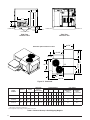
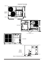
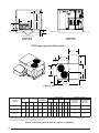
Figure 15. Physical Dimensions for R7TQ Units .......... 21
Table 3. Center of Gravity & Unit Shipping Weights .... 22
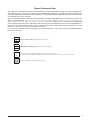
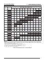
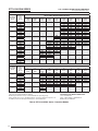
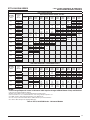
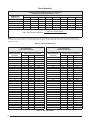
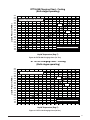
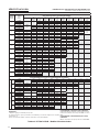
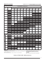
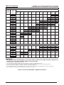
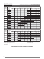
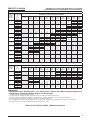
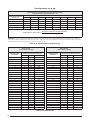
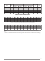
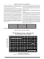
Blower Performance Data ................................................ 23
Table 4. R7TQ-072 C/D/N Series - Downflow Models . 24
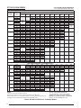
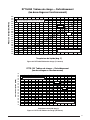
Table 5. R7TQ-072 C/D/N Series - Horizontal Models . 25
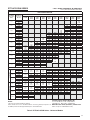
Table 6. R7TQ-090 C/D/N* Series - Downflow Models 26
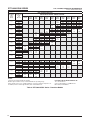
Table 7. R7TQ-090 C/D/N* Series - Horizontal Models 27
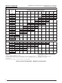
Table 8. R7TQ-120 C/D/N* Series - Downflow Models 28
Table 9. R7TQ-120 C/D/N*Series - Horizontal Models 29
Table 10. R7TQ-090C/D/N* Series High Static Drive .. 30
Table 11. R7TQ-120C/D/N* Series High Static Drive .. 30
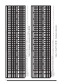
Electrical Data & Diagrams .............................................. 31
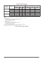
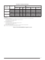
Table 12. Factory Unit MCA / MOP Data ..................... 31
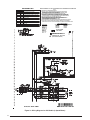
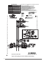
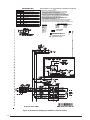
Figure 16. Wiring Diagram for 072 Models ................... 32
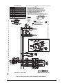
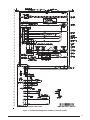
Figure 17. Wiring Diagram for 072 Models ................... 33
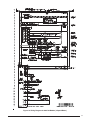
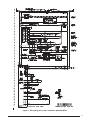
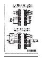
Figure 18. Wiring diagram for 090/ 120 Models
(2 Speed) .................................................... 34
Figure 19. Wiring Diagram for 090/120 Models
(3 Speed) .................................................... 35
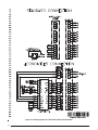
Figure 20. Wiring Diagram for 090 / 120 Models With
ECM Motor .................................................. 36
Figure 21. Wiring Diagram for 090 / 120 Models With
ECM Motor .................................................. 37
Figure 22. Wiring Diagram for Units With Optional
Economizer ................................................. 38
Figure 23. Wiring Diagram for Models With 3 HP
ECM Motor .................................................. 39
Gas Information ............................................................... 40
Table 13. Gas Pipe Capacities ..................................... 40
Table 14. Gas Flow Rates ............................................ 40
Table 15. Heat Rise and Range ................................... 41
Table 16. Natural Gas High Altitude (Ft.) Drill Sizes .... 41
Table 17. LP Gas Conversion and LP Gas High
Altitude (Ft.) Conversion Drill Sizes .............. 41
Figure 24. Inlet & Manifold Pressure Tap Locations .... 42
Figure 25. Regulator Spring & Adjustment
Screw Removal ........................................... 42
Converting Between Natural and LP Gas ........................ 43
Figure 26. Honeywell Gas Valve (VR8305 ) ................. 43
Figure 27. Gas Valve Label for 6 Ton - Operating
Instructions .................................................. 44
Figure 28. Gas Valve Label for 7.5 & 10 Ton -
Operating Instructions ................................. 45
Charging Charts & Application Notes .............................. 46
Table 18. Refrigerant Charge Table ............................. 46
Figure 29. R7TQ-072 Charging Chart (6-Ton) ............. 46
Figure 30. R7TQ-090 Charging Chart (7.5-Ton) .......... 47
Figure 31. R7TQ-120 Charging Chart (10-Ton) ........... 47
49

3
IMPORTANT SAFETY INFORMATION
Please read all instructions before servicing this equipment.
Pay attention to all safety warnings and any other special
notes highlighted in the manual. Safety markings are used
frequently throughout this manual to designate a degree or
level of seriousness and should not be ignored.
WARNING indicates a potentially hazardous situation that if
not avoided, could result in personal injury or death.
CAUTION indicates a potentially hazardous situation that
if not avoided, may result in minor or moderate injury or
property damage.
WARNING:
WARNING:
WARNING:
PROPOSITION 65 WARNING: This product
WARNING:
• Thisequipmentcontainsliquidandgaseousrefrigerant
under high pressure. Installation or servicing should only
be performed by qualified trained personnel thoroughly
familiar with this type equipment.
• Beforebeginningtheinstallation,verifythattheunitmodel
is correct for the job. The unit model number is printed on
the data label.
• Never test for gas leaks with an open ame. Use
a commercially available soap solution to check all
connections See
page 10.
• Followallprecautionsintheliterature,ontags,andon
labels provided with the equipment. Read and thoroughly
understand the instructions provided with the equipment
prior to performing the installation and operational checkout
of the equipment.
• This unit is designedonlyfor outdoor installations and
should be located with consideration of minimizing the
length of the supply and return ducts.
• Theinstallershouldbecomefamiliarwiththeunit’swiring
diagram before making any electrical connections to the
unit. See the unit wiring label or
Figure 16 (page 32), Figure
17 (page 33)
, Figure 18 (page 34), Figure 19 (page 35),
Figure 20 (page 36), Figure 21 (page 37), Figure 22 (page
38)
, & Figure 23 (page 39).
• Use caution whenhandling this applianceorremoving
components. Personal injury can occur from sharp metal
edges present in all sheet metal constructed equipment.
• Allelectricalwiringmustbecompletedinaccordancewith
local, state and national codes and regulations and with
the National Electric Code (ANSI/NFPA 70) or in Canada
the Canadian Electric Code Part 1 CSA C.22.1.
• The installer must comply with all local codes and
regulations which govern the installation of this type of
equipment. Local codes and regulations take precedence
over any recommendations contained in these instructions.
Consult local building codes and the National Electrical
Code (ANSI CI) for special installation requirements.
• AirDuctsmustbeinstalledinaccordancewiththestandards
of the National Fire Protection Association “Standards for

4
Installation of Air Conditioning and Ventilation Systems”
(NFPA 90A), “Standard for Installation of Residence Type
Warm Air Heating and Air Conditioning Systems” (NFPA
90B), these instructions, and all applicable local codes.
• Consult
Table 15 (page 41), and the rating plate for
the proper circulating air flow and temperature rise. It is
important that the duct system be designed to provide the
correct flow rates and external pressure rise. An improperly
designed duct system can result in nuisance shutdowns,
and comfort or noise issues.
• This unit isdesigned foroutdoor installations onlyand
should be located as described on
page 4.
• Useonlywiththetypeofgasapprovedforthisunit.Refer
to the unit rating plate.
• Provideadequate combustionandventilationairtothe
unit. See
page 5 & page 6.
• Provideadequateclearancesaroundtheairventintake
terminal as specified on
page 5.
• Combustion products must be discharged outdoors.
Connect this unit to an approved vent system only, as
specified on
page 6.
• Theinformationlistedbelowisforreferencepurposesonly
and does not necessarily have jurisdiction over local or
state codes. Always consult with local authorities before
installing any gas appliance.
• US:NationalFuelGasCode(NFGC),AirforCombustion
and Ventilation
• CANADA:NaturalGasandPropaneInstallationCodes
(NSCNGPIC), Venting Systems and Air Supply for
Appliances
• USandCANADA:AirConditioningContractorsAssociation
(ACCA) Manual D, Sheet Metal and Air Conditioning
Contractors National Association (SMACNA), or American
Society of Heating, Refrigeration, and Air Conditioning
Engineers (ASHRAE) Fundamentals Handbook
Electrical Connections
• US:NationalElectricalCode(NEC)ANSI/NFPA70
• CANADA:CanadianElectricalCodeCSAC22.1
• US:NFGCandNationalPlumbingCodes
• CANADA:NSCNGPIC
General Installation
• US:CurrenteditionoftheNFGCandtheNFPA90B.For
copies, contact the National Fire Protection Association
Inc., Batterymarch Park, Quincy, MA 02269; or American
Gas Association, 400 N. Capitol, N.W., Washington DC
20001 or www.NFPA.org
• CANADA:NSCNGPIC.Foracopy,contactStandardSales,
CSA International, 178 Rexdale Boulevard, Etobicoke
(Toronto), Ontario, M9W 1R3 Canada
• US: (NFGC) NFPA 54–1999/ANSI Z223.1 and the
Installation Standards, Warm Air Heating and Air
Conditioning Systems ANSI/NFPA 90B.
• CANADA: CAN/CSA-B149.1 and .2–M00 National
Standard of Canada. (NSCNGPIC)
GENERAL INFORMATION
Single Package Gas Heating / Electric Cooling Rooftop
Units are designed only for outdoor rooftop or ground level
installations and can be readily connected to the duct system
of a building.
This unit has been tested for capacity and efficiency in
accordance with AHRI Standards and will provide many
years of safe and dependable comfort, providing it is properly
installed and maintained. With regular maintenance, this unit
will operate satisfactorily year after year. Abuse, improper
use, and/or improper maintenance can shorten the life of
the appliance and create unsafe hazards.
To achieve optimum performance and minimize equipment
failure, it is recommended that periodic maintenance be
performed on this unit. The ability to properly perform
maintenance on this equipment requires certain tools and
mechanical skills.
√ The cooling load of the area to be conditioned must be
calculated and a system of the proper capacity selected.
It is recommended that the area to be conditioned be
completely insulated and vapor sealed.
√ Check the electrical supply and verify the power supply
is adequate for unit operation. Consideration should be
given to availability of electric power, service access, noise,
and shade. If there is any question concerning the power
supply, contact the local power company.
√ All units are securely packed at the time of shipment and
upon arrival should be carefully inspected for damage prior
to installing the equipment at the job site. Verify coil fins
are straight. If necessary, comb fins to remove flattened
or bent fins. Claims for damage (apparent or concealed)
should be filed immediately with the carrier.
√ Please consult your dealer for maintenance information and
availability of maintenance contracts. Read all instructions
before installing the unit.
Locating the Unit
• Surveythejobsitetodeterminethebestlocationforthe
packaged unit. The unit should be located with consideration
of minimizing the length of the supply and return ducts.
If practical, place the equipment and its ducts in an area
where they will be shaded from the afternoon sun, when
the heat load is greatest.
• Selectasolid,levelposition,preferablyonaconcreteslab,
slightly above the grade level, and parallel to the building.
• Overheadobstructions,poorlyventilatedareas,andareas
subject to accumulation of debris should be avoided. Do
not place the unit in a confined space or recessed area
where discharge air from the unit could re-circulate back
through the condenser coil.
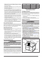
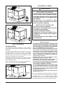
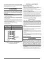
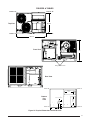
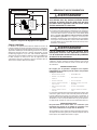
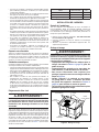
• Sufcientclearanceforunobstructedairowthroughthe
louvered control access panel and outdoor coil must be
maintained in order to achieve rated performance. See
Figure 1 (page 5) for minimum clearance requirements.

5
Heating Load
This unit should be sized to provide the design heating
load requirement. Heating load estimates can be made
using approved methods available from Air Conditioning
Contractors of America (Manual N); American Society of
Heating, Refrigerating, and Air Conditioning Engineers; or
other approved engineering methods. For installations above
2,000 ft., the unit should have a sea level input rating large
enough that it will meet the heating load after deration for
the installed elevation.
WARNING:
Provisions must be made during the installation of this unit
that provide an adequate supply of air for combustion.
• Instructionsfordeterminingtheadequacyofaninstallation
can be found in the current revision of the NFGC (ANSI
Z223.1 / NFPA54). Consult local codes for special
. These requirements are for US installations
as found in the NFGC.
• The requirements in Canada (B149.1) are structured
differently. Consult with B149.1 and local code officials
for Canadian installations.
WARNING:
To maximize heat exchanger life, the combustion air must
be free of chemicals which form corrosive acidic compounds
in the combustion gases.
IMPORTANT NOTE:
• CarbontetraChloride • Gasoline/Kerosene
• Cements,Glues,paintremovers,
varnishes,etC.
• h
aloGentyperefriGerants
• CleaninGsolvents • hydroChloriCaCid
• ChlorinebasedswimminGpool
ChemiCals
• masonryaCidwashinGmaterials
• Chlorinatedwaxes&Cleaners • permanentwavesolutions
• de-iCinGsaltsorChemiCals • watersofteninGChemiCals
Air openings in the door of the unit, warm air registers, and
return air grilles must never be restricted. If the unit does
not receive an adequate supply of air for combustion, the
flame roll-out control located above the burners will open,
turning off the gas supply to the burners. This safety device
is a manually reset switch.
IMPORTANT NOTE:
If this control must be replaced, use only factory authorized
replacement parts specified in the Replacement Parts List
provided online.
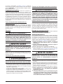
Top of unit
to be
unobstructed
Recommended Clearances
for Service or Accesories
Minimum Required
Clearances to Combustibles
36"
36"
36"
36"
48"
48"
60"
48"

6
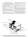
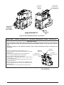
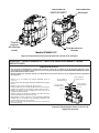
This unit has been equipped with an integral venting system
and designed to operate only with this venting system. If
desired, an accessory venting kit is available.
approved venting kit listed in the technical service
literature.
WARNING:
This unit is intended for outdoor installation
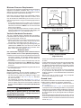
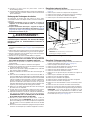
A vent cover assembly has been supplied with the unit and
can be found secured inside the compressor area of this
unit.
Figure 2 displays the proper installation of the vent cover
assembly over the vent outlet. The fasteners used to secure
the vent cover are affixed to the cover for transport.
The list below summarizes the location requirements for the
ventingsystemtermination:
• Thelocationoftheventterminationmustbeconsistent
withtheNationalFuelGasCode(ANSIZ223.1)orCAN/
CSA-B149 Installation Codes.
• Mustbelocatedatleast4feethorizontallyfromanyelectric
meters, gas meters, regulators, and relief equipment.
• Mustbelocatedatleast3feetaboveanyforcedairinlet
located within 10 feet of unit.
• Mustbelocatedatleast4feetbelow,4feethorizontally
from, or 1 foot above any door, window, or gravity air inlet
into any building.
• Mustbelocatedatleast1footabovegradeandinstalled
in such a manner as to prevent snow accumulation from
obstructing the vent termination.
• Theventterminationmustnotbelocatedaboveanypublic
walkways.
• Theventcoverassemblymustbeinstalledtoassureproper
operation of the unit.
• Makesuretheexhaustgaseswillnotimpingeonwindowsor
building surfaces, which may be compromised or damaged
by condensation.
• Donotinstalltheunitinalocationwhereexhaustfromthe
vent termination will be directed into windows, stairwells,
under decks, or other recessed areas.
CIRCULATING AIR SUPPLY
WARNING:
enter the return air ductwork or the circulating air
This unit is designed only for use with a supply and return
duct. Air ducts should be installed in accordance with
the standards of the National Fire Protection Association
“Standard for Installation of Air Conditioning Systems”
(NFPA 90A), “Standard for Installation of Residence Type
Warm Air Heating and Air Conditioning Systems” (NFPA
90B), and all applicable local codes. NFPA publications are
availablebywritingto:NationalFireProtectionAssociation,
BatterymarchPark,Quincy,ME02269orvisittheirwebsite:
www.NFPA.org.
Vent Cover

7
• DesigntheductworkaccordingtoManualQbytheAir
Conditioning Contractors of America (ACCA) or similar
commercial methods.
• Ifroofcurbisinstalled,theductsmustbeattachedtothe
curb hangers, not the unit.
• Ductworkshouldbeattacheddirectlytotheunitendpanel
for horizontal applications.
• Itisrecommendedthattheoutletductbeequippedwitha
removable access panel. This opening should be accessible
when the unit is installed in service and shall be of a size
such that the smoke or reflected light may be observed
inside the casing to indicate the presence of leaks in the
heat exchanger. The cover for the opening shall be attached
in such a manner as to prevent leaks.
• Ifoutsideairisutilizedasreturnairtotheunitforventilation
or to improve indoor air quality, the system must be designed
so that the return air to the unit is not less than 50° F (10°
C) during heating operation.
• Ifacombinationofindoorandoutdoorairisused,theducts
and damper system must be designed so that the return
air supply to the furnace is equal to the return air supply
under normal, indoor return air applications.
• Thisunit isshippedreadyforverticalductconnections
and is easily converted for horizontal duct connections.
Unconditioned Spaces
All ductwork passing through unconditioned space must be
properly insulated to prevent condensation and minimize duct
losses. Use insulation with an outer vapor barrier. Refer to
local codes for insulation material requirements.
Acoustical Ductwork
Certain installations may require the use of acoustical lining
inside the supply duct work.
• Acoustical insulation must be in accordance with the
current revision of the Sheet Metal and Air Conditioning
Contractors National Association (SMACNA) application
standard for duct liners.
• DuctliningmustbeULclassiedbattsorblanketswitha
fire hazard classification of FHC-25/50 or less.
• Fiberductworkmaybeusedinplaceofinternalductliners
if the fiber duct work is in accordance with the current
revision of the SMACNA construction standard on fibrous
glass ducts. Fibrous duct work and internal acoustical
lining must be NFPA Class 1 air ducts when tested per
UL Standard 181 for Class 1 ducts.
WARNING:
All return air must pass through the filters before entering the
unit. It is important that all filters be kept clean and replaced
frequently to ensure proper operation of unit. Dirty or clogged
filters will reduce the efficiency of the unit and result in unit
shutdowns. Air filter pressure drop must not exceed 0.08
inches WC. When replacing the air filters, a suitable air filter
must be installed ahead of the evaporator coil of the return
air system. Refer to
Table 1 for recommended filter sizes.
UNIT INSTALLATION
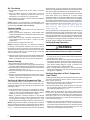
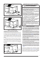
All units have been securely packaged at the point of shipment.
After unpacking the unit, carefully inspect for apparent and
concealed damage. Claims for damage should be filed with
the carrier by the consignee.
1. Remove any shipping brackets.
2. Inspect unit thoroughly for shipping damage.
3. Carefully lower and position unit to its permanent location.
WARNING:
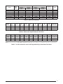
22
Figure 3.
22 for
UNIT
FACTORY
FILTER SIZE
QTY
R7TQ-072 20 x 20 x 2 4
R7TQ-090 20 x 20 x 2 4
R7TQ-120 20 x 20 x 2 4
LIFTING
BEAM
CABLE OR CHAIN
SPREADER
BAR
SPREADER
BAR
BASE
RAIL
BASE
RAIL

8
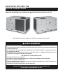
R7TQ units are certified as combination heating and cooling
equipment for outdoor installation only.
Figure 1 (page 5)
displays the minimum clearances to combustible materials
for both Downflow and Horizontal discharge.
R7TQ units may be installed on non-combustible surfaces
when used with bottom supply and return air ducts. Units
may be installed on wood flooring or on Class A, B, or C
roof covering material as long as the following requirements
aremet:
• Ifusingsidesupplywithreturnairducts,theunitmustbe
converted for horizontal connections. Refer to Vertical to
Horizontal section below. NOTE: This must be converted
prior to unit installation.
• Ifusingverticaldischargeandreturnairductsaroofcurb
must be installed prior to unit installation. See Rigging and
Hoisting section
(page 7) for setting of the unit.
The unit is shipped ready for downflow duct connections.
If horizontal ducts are required, the unit must be converted
prior to attaching duct work to unit.
1. Remove both return and supply horizontal duct covers.
Do not discard the covers. These will be used to cover
the openings in the bottom of the unit. See
Figure 4.
2. Cut both return and supply openings following along the
tabbed cutouts. NOTE: There are tabs on the inside and
the outside of the panels. Discard the cut sections when
done. These will not be needed.
Figure 5.
IMPORTANT NOTE:
Use caution when cutting left vertical side of return air
3. Remove 2 screws securing the air baffle bracket to the heat
exchanger air baffles. This provides additional clearance
for correct positioning of the supply air cover below the
heat tubes.
4. Install the duct covers that were removed in step 1 over the
openings in the bottom of the unit. NOTE: Apply adhesive
to one side of each cover and secure them to the bottom
of the unit.
5. Install the covers using predrilled locating holes and reinstall
the air baffle bracket.
Rooftop Mounting
Rooftop installations must be located according to local
buildingcodesorordinancesandtheserequirements:
• Theroofmustbecapableofhandlingtheweightofthe
unit. For unit weights, see
Table 3 (page 22). Reinforce
the roof if necessary.
• The appropriate accessory roof curb
Figure 6 (page 9)
must be installed prior to unit installation. The roof curb
must be square and level to ensure proper condensate
drainage. Please follow all instructions provided with
the kit.
WARNING:
• Onbottomdischargeapplications,thesupplyandreturn
air ducts must be attached to the roof curb duct supports,
not the unit. Install all ductwork before setting unit on curb
or frame.
• Framesupportmustbeconstructedusingnoncombustible
materials. Full perimeter support is required under the
unit. Supports must be made of steel or weather resistant
wooden materials. The unit must be square and level to
ensure proper condensate drainage.
• The frame must be high enough to ensure prevention
of any moisture from entering the unit. Recommended
height to unit base is 18” for both downflow and horizontal
installations.
• Secure roof curb or frame to roof using acceptable
mechanical methods per local codes.
Ground Level
Ground level installations must be located according to local
buildingcodesorordinancesandtheserequirements:
• Clearancesmustbeinaccordancewiththoseshownin
Figure 1 (page 5).
• A mounting pad
Figure 7 (page 9) must be provided
and separate from the building foundation. The pad must
be level to ensure proper condensate disposal and strong
enoughtosupporttheunit’sweight.Theslabheightmust
be a minimum of 3” (8 cm) above grade and with adequate
drainage.
• Whenusinghorizontalsupplywithreturnairducts,theunit
must be converted for horizontal connections prior to unit
installation. Refer to the Vertical to Horizontal conversion
section on
page 8.
Covers removed
Exposing area for
cutouts-connecting tabs

9
Condensate Drain
The method for disposing of condensate varies according
to local codes. Consult your local code or authority having
jurisdiction.
Condensate is drained from the unit through a 3/4” (19 mm)
PVC pipe located on end of the unit (
Figure 8). For proper
drainage, install a 3” (8 cm) Min. trap between the drain
line and an open vent of the same size. Avoid areas where
condensate drainage may cause problems.
The condensate drain line must be J-trapped using field
supplied parts and may be combined with other drain lines
when routed to the drain.
When connecting rigid drain line, hold any fittings with a
wrench to prevent twisting. Do not overtighten!
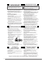
WARNING:
FIRE OR EXPLOSION HAZARD
WHAT TO DO IF YOU SMELL GAS
IMPORTANT NOTES:
the latest edition of the National Fuel Gas Code ANSI
Figure 9
Figure 9.
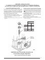
This unit is shipped from the factory for natural gas operation
at sea level elevation and is equipped with an orifice at
each burner.
Table 13 (page 40), lists gas pipe capacities
for standard pipe sizes as a function of length in typical
applications based on nominal pressure drop in the line.
See Table 3
Roof Curb
Condensate
Drain
Condensate Drain
Mounting Pad
3”

10
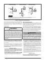
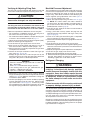
This unit only has right side gas entry. When connecting
the gas, provide clearance between the gas supply line and
theentryholeintheunit’scasingtoavoidunwantednoise
and/or damage to the unit. A typical gas service hookup is
shown in
Figure 9.
Leak Check
WARNING:
FIRE OR EXPLOSION HAZARD
After the gas piping to the unit is complete, all connections
must be tested for gas leaks. This includes pipe connections
at the main gas valve, emergency shutoff valve and other
gas connectors.
The soap and water solution can be applied on each joint or
union using a small paintbrush. If any bubbling is observed,
the connection is not sealed adequately and must be
retightened. Repeat the tightening and soap check process
until bubbling ceases.
IMPORTANT NOTES:
•
•
High Altitude Deration
High altitude application with this unit depends on the
installation altitude and the heating value of the gas. At high
altitudes, the heating value of natural gas is always lower
than the heating value at sea level.
All installations of this equipment must be made in accordance
with the National Fuel Gas Code or with local jurisdiction
codes. For installations at exactly 2,000 feet in altitude or
under, the installer does not need to derate the heat exchanger
performance. For any installation that exceeds 2,000 feet,
pleaseseethefollowinginstructionsandexample:
WARNING:
• Ifinstallingthisunitabove2,000feet,theinputratemust
bereduced4%per1,000feetofaltitude(Example:12%
at 3,000 feet, 16% at 4,000 feet, etc.). Always round up
to the next highest value of 1,000. So an installation at
3,120 feet is derated by 16% due to rounding up to 4,000.
NOTE: This deration is necessary to compensate for low
atmospheric pressure at high altitudes. Generally this will
require obtaining the gas heating value from the local gas
utility and replacing the burner orifices.
•
Table 17 (page 41) lists the correct orifice size to use at
different altitudes. To determine the unit rating and orifice
size, see the installation example on
page 11.
• Afterchangingtheorices,itisrequiredthatyoumeasure
the gas input rate by clocking the gas meter and using
the local gas heating value. See section on Verifying and
Adjusting the Firing Rate on
page 15.
IMPORTANT NOTE:
1. All piping must comply with local codes, ordinances, and/or National Fuel Gas Codes.
2. A manual shutoff valve must be installed within 6 feet of this equipment.
3. Always include a drip leg in piping.
NOTES:
Gas Valve
Gas Valve
Riser
3 in.
Minimum
Horizontal
Drop
Piped Gas Supply
Tubing Gas Supply
3 in.
Minimum
Horizontal
Drop
Gas Valve
3 in.
Min.
Riser
Piped Gas Supply

11
Conversion to LP/Propane
WARNING:
In the U.S., if installing the unit above 2,000 ft., refer to Table
17 (page 41)
to determine the correct orifice size. When
conversion is complete, verify the input rate is correct as
listed in the tables. Approved conversion kit must be used.
Please follow the instructions provided with each kit.
INSTALLATION EXAMPLE:
Elevation:
Natural
Unit Model:
At 4,000 feet, the unit needs to be derated by 4% for each
1,000 feet of elevation. This equates to 16% or less than
the sea level rating of 200,000 Btu/h.
1. Determineunitinputrating:
[200k x (100-16)%] = 168,000 Btuh. The required heating
rate for 3,890 feet is 168,000 Btu/h.
2. Determineoricesize:
From
Table 16 (page 41), find the BTU output. Follow
across the row and stop at the 3,000-4,000 elevation
columns. For this example, the orifice size displayed is
#31. Install one #31 orifice in every burner and check
firing rate. In this example, the firing rate must not exceed
168,000 Btu/h.
ELECTRICAL WIRING
WARNING:
EXPLOSION HAZARD
Pre-Electrical Checklist
√ Verify that the voltage, frequency, and phase of the supply
source match the specifications on the unit rating plate.
√ Verify that the service provided by the utility is sufficient
to handle the additional load imposed by this equipment.
For proper MCA / MOP data see the unit wiring label or
Table 12 (page 31).
√ Verify factory wiring is in accordance with the unit wiring
diagram. Inspect for loose connections.
√ For 3 phase units always check the phase balance. See
page 12.
• Electrical connections must be in compliance with all
applicable local codes and ordinances, and with the current
revision of the National Electric Code (ANSI/NFPA 70).
For Canadian installations the electrical connections and
grounding shall comply with the current Canadian Electrical
Code (CSA C22.1 and/or local codes).
• Providepowersupplyfortheunitinaccordancewiththe
unit wiring diagram and the unit rating plate. The line
voltage to the unit should be supplied from a dedicated
branch circuit containing the correct fuse or circuit breaker
for the unit.
•
This switch shall
be capable of electrically de-energizing the outdoor unit.
See unit data label for proper incoming field wiring. Any
other wiring methods must be acceptable to authority
having jurisdiction.
• A wiringdiagram is located on the inside coverof the
control access panel of the outdoor unit. The installer
should become familiar with the wiring diagrams before
making any electrical connections to the outdoor unit. See
Figure 16 (page 32), Figure 17 (page 33), Figure 18 (page
34)
, Figure 19 (page 35), Figure 20 (page 36), Figure 21
(page 37)
, Figure 22 (page 38), & Figure 23 (page 39).
• Ifanyoftheoriginalwiressuppliedwiththeunitmustbe
replaced, they must be replaced with material of the same
voltage, gauge, and temperature rating.
• Connect the line-voltage leads to the terminals on the
3-pole terminal block (inside the control compartment).
• Useonlycopperwireforthelinevoltagepowersupply

12
to this unit. Use proper code agency listed conduit and
connector for connecting the supply wires. Use of rain
tight conduit is recommended.
• Unitsareshippedfromthefactorywiredfor230or460volt
operation. On 208-230V units being placed into 208 volt
operation, remove the lead from the transformer terminal
marked 240V and connect it to the terminal marked 208V.
• Overcurrent protection must beprovided at the branch
circuit distribution panel and sized as shown on the unit
rating label and according to the National Electric Code
and applicable local codes. NOTE: See the unit rating plate
for maximum circuit ampacity and maximum overcurrent
protection limits.
Grounding
WARNING:
use gas piping as an electrical ground
!
This unit must be electrically grounded in accordance with
local codes or, in the absence of local codes, with the National
Electrical Code (ANSI/NFPA 70) or the CSA C22.1 Electrical
Code. Use the grounding lug provided in the control box for
grounding the unit.
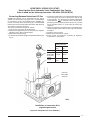
Voltage unbalance occurs when the voltages of all phases
of a 3-phase power supply are no longer equal. This
unbalance reduces motor efficiency and performance. Some
underlyingcausesofvoltageunbalancemayinclude:Lack
of symmetry in transmission lines, large single-phase loads,
and unbalanced or overloaded transformers. A motor should
never be operated when a phase imbalance in supply is
greater than 2%.
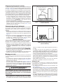
Perform the following steps to determine the percentage of
voltageimbalance:
1. Measure the line voltages
of your 3-phase power
supply where it enters the
building and at a location
that will only be dedicated
to the unit installation. (at
the units circuit protection
or disconnect).
EXAMPLE:
AB = 451V
BC = 460V
AC = 453V
2. Determine the average voltage in the power supply.
In this example, the measured line voltages were 451, 460,
and 453. The average would be 454 volts (451 + 460 +
453 = 1,364 / 3 = 454).
3.Determinethemaximumdeviation:
EXAMPLE
From the values given in step 1, the BC voltage (460V) is
thegreatestdifferenceinvaluefromtheaverage:
460 - 454 = 6
454 - 451 = 3
454 - 453 = 1
4. Determine percent of
voltage imbalance by
using the results from
steps 2 & 3 in the following
equation.
6
454
100 x
= 1.32%
EXAMPLE
maxvoltage deviation
fromaverage voltage
=100 x
averagevoltage
% Voltage Imbalance
The amount of phase imbalance (1.32%) is satisfactory
since the amount is lower than the maximum allowable 2%.
Please contact your local electric utility company if your
voltage imbalance is more than 2%.
• SinglePackageGasHeating/ElectricCoolingRooftop
Units are designed to operate with a 24 VAC Class II
control circuit. The control circuit wiring must comply with
the current provisions of the NEC (ANSI/NFPA 70) and
with applicable local codes having jurisdiction. Thermostat
connections should be made in accordance with the
instructions supplied with the thermostat.
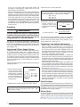
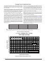
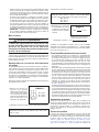
• A two-stage heating/cooling thermostat is required for
R7TQ series units. Select a thermostat which operates in
conjunction with the installed accessories. See Figure 10
for proper wire gauge and their recommended lengths for
typical thermostat connections.
• Thelowvoltagewiresmustbeproperlyconnectedtothe
units low voltage terminal block. Route 24V control wires
through the gas furnace side of the unit. Recommended wire
gauge and wire lengths for typical thermostat connections
are shown in
Figure 10 (page 13).
• Thethermostatshouldbemountedabout5feetabovethe
floor on an inside wall. DO NOT install the thermostat on
an outside wall or any other location where its operation
may be adversely affected by radiant heat from fireplaces,
sunlight, or lighting fixtures, and convective heat from
warm air registers or electrical appliances. Refer to the
thermostatmanufacturer’sinstructionsheetfordetailed
mounting information.
Heat Anticipator
Verify if the thermostat being used for the installation has a
heat anticipator setting. This function allows the thermostat to
anticipate the space heating rate and time the burner to shutoff
accordingly.Alwaysrefertothethermostatmanufacturer’s
instructions for the correct settings.
Blower Speed
The blower speed is preset at the factory but must be verified
at each installation. For optimum system performance and
comfort, it may be necessary to change the factory set speed.
Refer to
Table 4 (page 24), Table 5 (page 25), Table 6 (page
26)
, Table 7 (page 27), Table 8 (page 28), Table 9 (page

13
29), Table 10 (page 30), & Table 11 (page 30) for proper
blower performance data. Always ensure drive belt is secure
and tensioned properly. Also inspect variable pitch sheaves
for proper tightness of the set screws
CAUTION:
Tochangetheblowerspeed:
1. Disconnect all electrical power to the unit and open
the blower access door.
2. Loosen the motor mounting nuts and mounting plate
adjustment bolt to allow removal of the blower belt from
the motor sheave.
3. Loosen top set screw on motor sheave and turn clockwise
to close (increases blower speed), or counterclockwise to
open (decreases blower speed).
4. Replace belt on pulleys and position motor mounting plate
to correct position for proper belt tension.
5. Tighten motor nuts.
Pre-Start Check List
√ Verify unit is properly supported.
√ Verify unit is level for proper condensate drainage.
√ Verify all clearance requirements are met. Airflow to and
from the outdoor coil must be unrestricted.
√ Verify the ductwork is adequately sealed to prevent air
leakage. Insulate if necessary.
√ Verify the line voltage power leads are securely connected
and the unit is properly grounded.
√ Verify low voltage wires are securely connected to the
correct leads in the low voltage area of the control box.
√ Verify gas line pressure. For natural gas, the line pressure
must not exceed 10.0 inches WC (0.36 psig), or be less than
5.5 inches WC (0.20 psig). For LP gas, the line pressure
must not exceed 14 inches WC (0.51 psig) and must not
be less than 11.0 inches WC (0.40 psig).
√ Verify the flame roll-out control is closed.
IMPORTANT NOTE:
correcting the fault condition which caused the control
√ Verify the gas line has been purged and all connections
are adequately sealed. To check for gas leakage, see
page
10
.
√ Verify the indoor blower is properly set for the installation.
√ Verify the outdoor fan turns freely.
√ Verify the power supply branch circuit overcurrent protection
is properly sized.
√ Verify all exterior panels have been reinstalled and securely
fastened.
√ Verify the thermostat is wired correctly and preset for initial
operation. Set the thermostat system switch to OFF and
the fan switch to AUTO.
Startup Procedures
WARNING:
Allow 24 hrs for heating of the refrigerant
• Checkallelectricalwiringforlooseconnectionsandtighten
as required.
• Checkunitforreturnairltersandcondensatetrap.
• Closeallelectricaldisconnectstoenergizethesystem.
T-Stat Wire
Gauge
18 Ga. 0 - 60
16 Ga. 61 - 130
Field Supplied Wiring - - - - - Use Solid Class II Copper Wire
Y1
Y2
W2
W1
G
RH
RC
Y1
Y2
W2
W1
G
R
Indoor
Thermostat
Sub-Base
Unit Low Voltage
Terminal
A1
Economizer
OCC/UNOCC

14
specified range, it may be necessary to change the blower
speed. Lowering the blower speed increases the temperature
rise and a higher speed decreases the temperature rise.
The unit is equipped with a belt driven blower and variable
pitch motor sheave. The selection of a sheave setting
should be based on the desired CFM and the duct system
parameters.RefertotheACCA’sManualQforacomplete
description of how to determine these parameters and Manual
N for determination of the commercial load requirements.
Blower performance data can be found in
Table 4 (page 24),
Table 5 (page 25), Table 6 (page 26), Table 7 (page 27),
Table 8 (page 28), Table 9 (page 29), Table 10 (page 30),
&
Table 11 (page 30).
The integrated control is designed to start the circulating air
blower 30 seconds after the gas valve opens and turns the
blower motor off 160 seconds after the gas valve is closed
during heating operation. For cooling the integrated control
is designed to start the circulating air blower 7 seconds after
the compressor energizes and turns the blower motor off 90
seconds after the compressor deenergizes.
WARNING:
1. Open the louvered control access panel (to ensure there
is power to the unit) and then remove the louvered heat
exchanger access panel.
2. Set the thermostat above room temperature and observe
the ignition sequence. The burner flame should carry over
immediately between all burners and should extend from
each burner without lifting off, curling, or floating. The
flames should be blue, without yellow tips.
3. After verifying flame characteristics, set the thermostat
below room temperature and verify that the burner flame
extinguishes completely.
To verify operation of the over-temperature limit control, make
sure the louvered control access panel is in place and that
there is power to the unit.
1. Block the return airflow to the unit by installing a close-off
plate in place of or upstream of the filter.
2. Set the thermostat above room temperature and verify
the unit operates with the correct sequence of operation.
See Operating Sequence (
page 16).
NOTE: The over-temperature limit control should function
to turn off the gas valve within approximately four minutes
(exact time depends on the efficiency of the close-off when
blocking the return air). The circulating air and combustion
blowers should continue to run when the over-temperature
limit control switch opens.
3. Remove the close-off plate immediately after the over-
temperature limit control opens. If the unit operates for
more than four minutes with no return air, set the thermostat
below room temperature, shut off power to the unit, and
replace the over-temperature limit control.
Air Circulation
1. Set thermostat system switch to OFF and the fan switch
to ON.
2. Verify the blower motor runs continuously. Check for
air delivery at the register(s). Ensure that there are no
obstructions at the registers or in the ductwork.
3. Set thermostat fan switch to AUTO and verify the blower
shuts down immediately.
NOTE: If blower is turning opposite of arrow direction, shut
off main power to the unit and switch any two field wires at
the disconnect. DO NOT alter unit wiring.
1. Set the thermostat system switch to COOL and the fan
switch to AUTO.
2. Lower the thermostat temperature switch below room
temperature and observe that the blower, both compressors
and fans) energize.
3. Verify blower is turning in direction indicated by arrow
and air discharged at the register is cooler than room
temperature.
4. Verify HI and LO refrigerant pressures.
NOTE: If refrigerant pressures are abnormal and blower
is rotating in the opposite direction of the arrow, shut off
main power to the unit and switch any two field wires at the
disconnect. Ensure proper rotation of the blower. DO NOT
alter unit wiring. Listen for any unusual noises. Locate the
source and correct as needed.
5. Allow the unit to run for several minutes. Set the temperature
selector above room temperature and verify that the fan,
blower, and compressors cycle off with the thermostat.
1. Set the thermostat to the lowest setting.
2. Follow the startup procedures on this page or the operating
instruction label inside the louvered control access panel.
3. Set the thermostat above room temperature and verify the
Operating Sequence. See
page 16.
4. Verify that the compressor and outdoor fan motor are not
energized.
5. Run the unit and after approximately five minutes, set the
thermostat below room temperature. Verify the shutdown
sequence. See Operating Sequence.
Verify the temperature rise through the unit is within the
range specified on the unit data label. Temperature rises
outside the specified range could result in premature heat
exchanger failure.
1. Place thermometers in the return and supply air stream
as close to the unit as possible. The thermometer on the
supply air side must be shielded against direct radiation
from the heat exchanger to avoid false readings.
2. Adjust all registers and duct dampers to the desired
position. Run the unit for 10 to 15 minutes before taking
any temperature readings. The temperature rise is the
difference between the supply and return air temperatures.
NOTE: For typical duct systems, the temperature rise will fall
within the range specified on the data label (with the blower
speed at the factory recommended setting) shown in
Table 15
(page 41)
. If the measured temperature rise falls outside the

15
The firing rate must be verified for both HIGH fire and LOW
fire for each installation to prevent over-firing of the unit.
CAUTION:
IMPORTANT NOTE:
Followthestepsbelowtodeterminetheunitringrate:
• Forinstallationsat2,000feetandless,theringrateis
the same as shown on the unit rating label.
• Forinstallationsabove2,000feet,computetheringrate
as shown in the installation example on
page 11.
1. Obtain the gas heating value from the gas supplier (HHV).
2. Shut off all other gas fired appliances.
3. Turn ON the main gas supply at the manual valve.
4. Start the unit in heating mode and allow it to run for at
least three minutes in HIGH fire mode (Stage 1 & 2).
5. Measure the time (in seconds) required for the gas meter
to complete one revolution.
6. Convert the time per revolution to cubic feet of gas per
hour using
Table 13 (page 40).
7. Multiply the gas flow rate in cubic feet per hour by the
heating value of the gas in Btu per cubic foot to obtain the
firing rate in Btu per hour. See Example below
.
EXAMPLE:
• Timefor1revolutionofagasmeterwitha1cubicfoot
dial = 40 seconds.
• From
Table 14 read 90 cubic feet gas per hour.
• Local heating value of the gas (obtained from gas
supplier) = 1,040 Btu per cubic foot.
• Inputrate=1,040x90=93,600Btuh.
8. Adjustments to the firing rate can be made by adjusting
the gas manifold pressure. See the High Altitude Deration
section (
page 10) for additional information of firing rate
at elevations above 2000 ft.
9. Low fire input (Stage 1) must also be verified by repeating
all steps outlined for high fire input rate. Obtain low fire
input values from
Table 15 (page 41). If necessary, follow
the manifold pressure adjustment instructions for the low
fire regulator spring to obtain the required input rate.
The manifold pressure for both HIGH and LOW firing rates
must be set to the appropriate value. To adjust the manifold
pressure for either high fire (stage 1& stage 2) or low fire
(stage 1 only), follow these instructions after identifying the
correct regulator spring adjustment screw from
Figure 25
(page 42)
foryourparticulargasvalve:
1. Obtain the required input firing rate from
Table 15 (page
41)
. NOTE: The values listed in the table is based on
sea level values. At higher altitudes, the heating value of
gas is lower than the sea level heating value. See High
Altitude Deration section (
page 10).
2. Turn OFF the gas supply at the manual valve located on
the outside of the unit.
3. Using a 3/16” Allen wrench, remove the plug from the
OUTLET pressure tap (OUTLET side of gas valve). See
Figure 24 (page 42).
4. Install an 1/8” NPT pipe thread fitting that is compatible
with a manometer or similar pressure gauge.
5. Connect the manometer or pressure gauge to the OUTLET
pressure tap.
6. Turn ON the main gas supply at the manual valve.
7. Remove the regulator cap. Turn the regulator adjusting screw
clockwise to increase the pressure or counterclockwise to
reduce the pressure.
8. Replace the regulator cap after adjustments are complete.
9. Turn OFF the gas supply at the manual valve.
10. Disconnect the Manometer or pressure gauge.
11. Remove the NPT fitting and reinstall the OUTLET pressure
tap plug. Hand tighten the plug first to prevent cross-
threading. Tighten with a 3/16” Allen wrench.
Refrigerant Charging
WARNING:
The R7TQ Series packaged gas/electric units are fully
charged at the factory and when installed accordingly, no
charging is required. The refrigerant charge can be checked
and adjusted through the service ports provided on the units.
Use only gauge lines which have a “Schrader” depression
device present to actuate the valve.
Refrigerant charging must be done by qualified personnel
familiar with safe and environmentally responsible refrigerant
handling procedures. See Unit Rating Plate for the proper
type and amount of refrigerant.

16
OPERATING SEQUENCE
The operating sequences for the heating, cooling, and fan
modesaredescribedbelow.Refertothewiringdiagrams:
Figure 16 (page 32), Figure 17 (page 33), Figure 18 (page
34)
, Figure 19 (page 35), Figure 20 (page 36), Figure 21
(page 37)
, Figure 22 (page 38), & Figure 23 (page 39).
Cooling Mode
1. On a call for cooling the thermostat closes, applying 24
VAC to Y1, G, & Y2 if Stage 2 cooling is calling.
2. G applies 24VAC to the main circulating blower circuit.
3. Y1 & Y2 apply 24VAC through all safety switches before
energizing their respective contactors.
4. When the thermostat is satisfied the contactors are de-
energized.
5. The circulating blower motor de-energizes immediately.
Heating Mode
1. On a call for heat, the thermostat closes, applying 24
VAC to the W1 terminal (and W2 terminal if Stage 2 heat
is required).
2. The integrated control monitors the safety circuit at all
times. If either the roll-out switch or the over-temperature
limit controls open, the gas valve will not energize. The
main blower continues to operate until the over-temperature
limits close, the flame roll-out switch is manually reset, or
the thermostat is satisfied.
3. The integrated control checks all safety switches at the
beginning of each heating cycle. If closed, the combustion
blower performs a 10 second pre-purge.
4. The integrated control will then supply power to the direct
spark ignitor and immediately energizes the gas valve.
NOTE: Burner operation begins in high fire mode with both
Stage 1 and Stage 2 gas valve energized, independent of
the thermostat call for Stage 2 heat. If after 30 seconds
of operation with no call for Stage 2 heat, the integrated
control will resume heating operation in low fire mode of
operation and Stage 2 gas valve is de-energized.
5. The flame must be proven through the flame sensor in
10 seconds to hold the gas valve open. The integrated
control will monitor the gas flame with the flame sensor
for the entire time the gas valve is open. If for any reason
the gas flame drops out, the gas valve will immediately
close. After 30 second purge, the integrated control will
try to ignite fourteen more times.
6. The main air blower will start and continue to run 40
seconds after the gas valve opens.
7. When the thermostat is satisfied, the integrated control is
de-energized. The gas valve and combustion blower de-
energize immediately while the main air blower continues
to run through the blower off delay of approximately 150
seconds.
8. If the unit fails to prove flame after fifteen ignition attempts,
it will go into a soft lockout. The unit will re-attempt the start-
up procedure every hour until the thermostat is satisfied
or 24 VAC power is removed from the unit for a minimum
period of 5 seconds. NOTE: See Troubleshooting section
(page 19) for a complete list of heating operation fault
codes.
Blower Mode
1. On a call for fan operation, the thermostat applies 24 VAC
directly to the blower contactor.
2. The circulating blower is energized immediately.
UNIT MAINTENANCE
WARNING:
EXPLOSION HAZARD
NOTE: These maintenance instructions are primarily intended
to assist qualified technicians experienced in the proper
maintenance and operation of this appliance.
To achieve optimum performance from the air conditioner
and minimize equipment failure, it is recommended that
periodic maintenance be performed on this unit. The ability
to properly perform maintenance on this equipment requires
certain mechanical skills and tools. Please consult your dealer
for maintenance information and availability of maintenance
contracts.
Routine Maintenance
Please consult your dealer for maintenance information and
availability of maintenance contracts. At a minimum, routine
maintenanceshouldincludethefollowingitems:
CAUTION:
Air Filters
WARNING:

17
It is recommended that the air filters be inspected and cleaned
or replaced every three to four weeks using filters of like size
and kind.
Table 1 (page 7) lists the factory installed filter
sizes and quantities for each unit. NOTE: R7TQ units are
equipped with 2” pleated disposable filters.
Blower Compartment
Buildup of dirt and lint on the blower and motor can create
excessive loads on the motor resulting in higher than normal
operating temperatures and possible shortened service life.
It is recommended that the blower compartment be cleaned
monthly during heating and cooling seasons to remove any
dirt and lint that may have accumulated in the compartment
or on the blower and motor. Inspect the blower drive belt for
cracks, excessive wear and proper tension after cleaning
the compartment.
Condensate Drain & Outdoor Coil
Inspect the condensate drain and outdoor coil at the begin-
ning of each cooling season. Remove any debris. Clean the
outdoor coil and hail guard louvers (optional) as necessary
using a mild detergent and water. Rinse thoroughly with water.
Electrical
WARNING:
CAUTION:
Inspect the electrical connections for tightness at the beginning
of each heating and cooling season. Service as necessary.
Motor / Bearing Lubrication
WARNING:
• Theblowerassemblyinthisunitisequippedwithtwosupport
bearings. The support bearings are sealed cartridge units
and require no further lubrication.
• Theindoorblowermotorispre-lubricatedatthefactory
and does not require additional lubrication.
• Thecombustionairblowermotorandoutdoorfanmotors
are equipped with pre-lubricated sealed ball bearings. No
further oiling is required for the life of this product
Heat Exchanger & Burner Maintenance
WARNING:
circulated into the occupied space can create
The unit should operate for many years without excessive
scale buildup in the heat exchanger, however, the heat
exchanger, the vent system, and the burners should be
inspected and cleaned (if required) by a qualified technician
annually to ensure continued safe operation. Particular
attention must be given to identify deterioration from corrosion
or other sources.
Vent Cover Assembly
Inspect and clean the screen of the vent cover assembly at
the beginning of each heating and cooling seasons.
Cleaning of Burners
It is recommended that the burners be inspected and cleaned
periodically (if required) by a qualified technician annually to
ensure continued safe operation. Particular attention must
be given to identify deterioration from corrosion or other
sources. If the burners must be cleaned, follow the steps
below. See
Figure 11 (page 18) for more detail.
3. Remove the louvered access panel from the unit.
4. Turn the gas control knob to the “OFF” position. See
Figure
27 (page 44)
and Figure 28 (page 45) for gas valve shut
off instructions.
CAUTION:
5. Disconnect the wires from the gas valve, ignitor, and flame
sensor.
6. Using two wrenches, separate the ground-joint union in
the gas supply piping at the unit.
7. Remove the piping between the gas valve and the ground-
joint union (if necessary).
8. Remove four screws securing the burner assembly to the
unit.
9. Carefully remove the burner assembly from the unit. DO
10. Inspect the burners for accumulated dust or debris. If
necessary, carefully clean them with a soft wire brush and/
or the nozzle of a vacuum cleaner. DO NOT DAMAGE
THE IGNITOR OR FLAME SENSOR WHILE CLEANING

18
11. Replace all the parts in reverse order from which they
were removed.
12. Follow the lighting instructions found on the right side door
to return the unit to operation. Verify proper operation
after servicing.
If the heat exchanger must be cleaned due to soot or scale
build up, follow the steps below.
Figure 27 (page
44
and 45 for gas valve shut off
WARNING:
3. Disconnect the wires from the gas valve, ignitor, and flame
sensor. See
Figure 11 (page 18) for wire locations.
4. Using two wrenches, separate the ground-joint union in
the gas supply piping at the unit.
5. Remove the piping between the gas valve and the ground-
joint union, if necessary.
6. Remove the four screws securing the burner assembly to
the unit.
7. Carefully remove the burner assembly from the unit. DO
NOT DAMAGE THE IGNITOR OR FLAME SENSOR
8. Remove 6 screws securing the combustion blower to the
collector pan.
9. Remove the complete combustion blower from the unit.
10. Remove the screws securing the collector box cover to
the unit and remove cover plate.
11. Remove the screws securing the balance plate to the
collector box and the balance plate.
12. Remove the turbulator from each heat exchanger tube.
13. Attach a round wire brush to a length of high grade stainless
steel cable, such as drain cleanout cable. Attach the other
end of the spring cable to a variable speed reversible drill.
Slowly insert and rotate the cable into the top portion of
the heat exchanger. Operate the drill alternating between
forward and reverse, working the cable in and out several
times to obtain sufficient cleaning. Repeat this sequence
for each heat exchanger tube.
14. Remove all loosened debris from the heat exchanger
tubes using a vacuum cleaner.
15. Using a light, check the condition of the upper and lower
sections of the heat exchanger tube.
16. Inspect the burners and if necessary, clean them carefully
with a soft wire brush and/or the nozzle of a vacuum
cleaner. DO NOT DAMAGE THE IGNITOR OR FLAME
17. Replace all the parts in reverse order from which they
were removed. NOTE: If screws or other hardware are
corroded, replace only with corrosion resistant stainless
steel hardware of similar design.
18. Follow the operating instructions found on the right side
doorandtheUser’sInformationManualtoreturntheunit
to operation.
1. Remove 3 screws securing the compressor access door.
See
Figure 11.
2. Remove the compressor access door from the unit.
3. Remove retaining screw and heat access panel.
4. Remove 4 screws securing the burner manifold.
5. Remove the burner manifold from the unit.
Turbulators
Access Panel
Retaining Screws
NOTE: Side panel omitted for clarity of heat exchanger removal
1. Remove 6 screws securing the venter housing plate from
the venter housing. See
Figure 12 (page 19).
2. Remove the venter housing plate from the venter housing.
3. Remove 4 screws securing the venter housing to the
collection box.
4. Remove the venter housing from the collection box.
5. Remove 8 screws securing the collection box to the
turning box.
6. Remove the collection box from the turning box.
7. Remove 4 screws securing the burner cover to the burner
support.
8. Remove the burner cover from the burner support.
9. Remove 4 screws from the burner support.
10. Remove the burner support from the unit.
11. Remove 20 screws securing the turning box to the unit.
12. Remove the turning box from the unit.
13. Remove 2 screws from the turbulators and pull out the
turbulators.
14. Remove 8 screws securing the horizontal supply air cover.
15. Remove the horizontal supply air cover from the unit.
16. Remove 2 nuts securing the heat exchanger rod.
NOTE: Support rod nuts (2) can be accessed through
blower compartment. Heat Exchanger tubes will exit out
horizontal supply air opening. See
Figure 13 (page 19).

19
Turning Box
Burner Cover
Burner Manifold
Mounting Screws
Collection Box
Venter Housing
Venter Housing Plate
NOTES: Support bracket screws (2) must be removed to install the duct cover.
Heat Exchanger tubes will exit out horizontal supply air opening.
Heat Exchanger
Support Rod
Support Rod Locations
TROUBLESHOOTING
If the unit does not operate properly in the cooling mode,
checkthefollowing:
• Thethermostatisoperatingproperly.
• Electricalpowertotheunitisturnedon.
• Allsafetyswitchesareclosed.
• Theservicedoorsareinplace.
• Transformercircuitbreakerisreset.
If the unit does not operate properly in the heating mode,
checkthefollowing:
• Thethermostatisoperatingproperly.
• Electricalpowertotheunitisturnedon.
• Allsafetyswitchesareclosed.
• Thegasisonandshut-offvalveisopen.
• Theservicedoorsareinplace.
• Theameroll-outcontrolisclosed.
• Refertothediagnosticcodesin
Table 2.
• Transformercircuitbreakerisreset.
Diagnostic Codes For 6 - 10 Ton Units
LED STATE
DESCRIPTION
COLOR CODE
GREEN STEADY ON NORMAL OPERATION NO CALL FOR HEAT
GREEN FAST FLASH NORMAL OPERATION CALL FOR HEAT
GREEN 1 FLASH
IN LOCK OUT FROM FIELD IGNITIONS OF
FLAME LOSSES
GREEN 2 FLASH
PRESSURE SWITCH DOES NOT CLOSE
WITHIN30SECONDSOFVENTERENERGIZED
GREEN 3 FLASH LIMIT SWITCH OPEN
GREEN 4 FLASH
PRESSURE SWITCH IS CLOSED BEFORE
VENTERISENERGIZED
GREEN STEADY OFF INTERNAL CONTROL FAULT OR NO POWER
YELLOW STEADY ON FLAME SENSED
YELLOW SLOW FLASH WEAK FLAME
YELLOW FAST FLASH
UNDESIRED FLAME (VALVE OPEN & NO
CALLFOR HEAT)

20
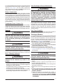
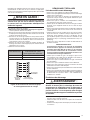
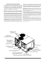
Electrical Control Panel
Single Point
Electrical Connection
Compressor(s)
Fuel Line Inlet
Blower
Heat Exchanger
Return Air
Supply Air
Condensate Drain
Condenser
Fans
Exhaust
Vent
Base
Rails
Heat Exchanger
Inspection Cover
COMPONENT FUNCTIONS
The descriptions below are various functional components
that affect the operation and shutting down of this unit. Some
of these components and their locations are shown in
Figure
14
. If any component on this unit must be replaced, use
only factory authorized replacement parts specified in the
Replacement Parts List provided online.
Pressure Switch - The pressure switch acts to verify that
the inducer motor is running. Combustion gases are drawn
through the heat exchanger tubes and vented through the
vent system.
- The flame roll-out control acts
to verify that the burner flame is being drawn into the heat
exchanger tubes. If the burner flame is not being drawn into
the heat exchanger tubes, the roll-out control will open within
several seconds. The combustion blower will continue to
operate if the flame roll-out control opens until it is manually
reset.
The flame sensor acts to prove that flame
has carried over from the ignitor to the right-most burner. If
no flame is sensed, the unit will be shut down automatically
and attempt two additional ignition trials before going into
lockout. Recovery from lockout requires a manual reset by
either resetting the thermostat or removing 24 volts for a
period of 5 seconds. If the thermostat is still calling for heat
after one hour the control will automatically reset and attempt
to ignite the burner again.
- The gas valve controls the flow of gas to the
burners in both low and high fire. When the valve is energized,
it automatically opens and regulates the gas pressure to the
manifold.
High Pressure Switch - This factory installed switch is
designed to de-energize the unit when excessive pressure
occurs due to abnormal conditions. Under normal conditions,
the switch is closed. If the discharge pressure rises above 650
psig, then the switch will open and de-energize the outdoor
unit. The switch is a manually reset type and will remain open
until the button on top of the switch is depressed.
- The over-temperature
limit control acts to prevent the air temperature leaving the
unit from exceeding the maximum outlet air temperature.
If the limit opens, the blower limit relay will energize. The
circulating air blower and combustion blower will continue to
operate if the over-temperature limit control opens.
La page charge ...
La page charge ...
La page charge ...
La page charge ...
La page charge ...
La page charge ...
La page charge ...
La page charge ...
La page charge ...
La page charge ...
La page charge ...
La page charge ...
La page charge ...
La page charge ...
La page charge ...
La page charge ...
La page charge ...
La page charge ...
La page charge ...
La page charge ...
La page charge ...
La page charge ...
La page charge ...
La page charge ...
La page charge ...
La page charge ...
La page charge ...
La page charge ...
La page charge ...
La page charge ...
La page charge ...
La page charge ...
La page charge ...
La page charge ...
La page charge ...
La page charge ...
La page charge ...
La page charge ...
La page charge ...
La page charge ...
La page charge ...
La page charge ...
La page charge ...
La page charge ...
La page charge ...
La page charge ...
La page charge ...
La page charge ...
La page charge ...
La page charge ...
La page charge ...
La page charge ...
La page charge ...
La page charge ...
La page charge ...
La page charge ...
La page charge ...
La page charge ...
La page charge ...
La page charge ...
La page charge ...
La page charge ...
La page charge ...
La page charge ...
La page charge ...
La page charge ...
La page charge ...
La page charge ...
La page charge ...
La page charge ...
La page charge ...
La page charge ...
La page charge ...
La page charge ...
La page charge ...
La page charge ...
-
 1
1
-
 2
2
-
 3
3
-
 4
4
-
 5
5
-
 6
6
-
 7
7
-
 8
8
-
 9
9
-
 10
10
-
 11
11
-
 12
12
-
 13
13
-
 14
14
-
 15
15
-
 16
16
-
 17
17
-
 18
18
-
 19
19
-
 20
20
-
 21
21
-
 22
22
-
 23
23
-
 24
24
-
 25
25
-
 26
26
-
 27
27
-
 28
28
-
 29
29
-
 30
30
-
 31
31
-
 32
32
-
 33
33
-
 34
34
-
 35
35
-
 36
36
-
 37
37
-
 38
38
-
 39
39
-
 40
40
-
 41
41
-
 42
42
-
 43
43
-
 44
44
-
 45
45
-
 46
46
-
 47
47
-
 48
48
-
 49
49
-
 50
50
-
 51
51
-
 52
52
-
 53
53
-
 54
54
-
 55
55
-
 56
56
-
 57
57
-
 58
58
-
 59
59
-
 60
60
-
 61
61
-
 62
62
-
 63
63
-
 64
64
-
 65
65
-
 66
66
-
 67
67
-
 68
68
-
 69
69
-
 70
70
-
 71
71
-
 72
72
-
 73
73
-
 74
74
-
 75
75
-
 76
76
-
 77
77
-
 78
78
-
 79
79
-
 80
80
-
 81
81
-
 82
82
-
 83
83
-
 84
84
-
 85
85
-
 86
86
-
 87
87
-
 88
88
-
 89
89
-
 90
90
-
 91
91
-
 92
92
-
 93
93
-
 94
94
-
 95
95
-
 96
96


dans d''autres langues
- English: Unbranded R7TQ Installation guide
Documents connexes
-
Unbranded P7TQ Guide d'installation
-
Miller GSA2QD Guide d'installation
-
Miller HSA1QE Guide d'installation
-
GrandAire KG7T(C,L) Guide d'installation
-
Unbranded R6GP 6, 7.5 - 10 Ton Archived 2/23/12 Guide d'installation
-
-
Miller C8QA Guide d'installation
-
-
-
Medallion R8GE, Three Phase Guide d'installation
Autres documents
-
Reznor R7TQ Manuel utilisateur
-
Maytag FSA3BF Guide d'installation
-
Mammoth R8GE, Single Phase Guide d'installation
-
Honeywell ST9103A Manuel utilisateur
-
Ingersoll-Rand M-Series Installation And Operation Manua
-
Greenheck 468410 SAF Mode d'emploi
-
White Rodgers 50M56-743 Direct Replacement Furnace Control for Goodman Multi Speed Nitride Ignition Integrated Furnace Control Guide d'installation
-
EINHELL GC-DP 3730 Product Sheet
-
BOUYER GZ-774-NTB Fiche technique
-
PC Products 071021 Guide d'installation