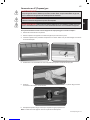
NAPOLEON GSS48 Manuel utilisateur
- Catégorie
- Cheminées
- Taper
- Manuel utilisateur

www.napoleongrills.com
1
EN
FR
PG.33
APPLY SERIAL NUMBER LABEL FROM CARTON
Serial No.
XXXXXX000000
MODEL NO.
INSTALLER: LEAVE THIS MANUAL WITH THE APPLIANCE.
CONSUMER: RETAIN THIS MANUAL FOR FUTURE REFERENCE.
DANGER
IF YOU SMELL GAS:
DANGER! CARBON MONOXIDE HAZARD
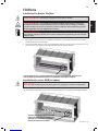
OUTDOOR GAS FIREPLACE
GSS48 / GSS48ST
WARNING!
N415-0346 MAR 16.15
WARNING!
NOTE!
WARNING
Napoleon Group of Companies
214 Bayview Dr., Barrie, Ontario, Canada L4N 4Y8
Phone: 1-705-726-4278 Fax: (705)-725-2564
www.napoleongrills.com
Customer Soluons: 1-866-820-8686 or grills@napoleonproducts.com

www.napoleongrills.com
2
EN
NAPOLEON products are designed with superior components and materials, and are
assembled by trained crasmen who take great pride in their work. Every component
has been thoroughly inspected by a qualied technician before packaging and shipping
to ensure that you, the customer, receive the quality product you expect from
NAPOLEON.
NAPOLEON warrants that components in your new NAPOLEON product will be free from defects in
material and workmanship from the date of purchase, for the following period:
Stainless steel burner assembly 5 years
Stainless steel housing 5 years
Aluminum table top and pedestal 5 years
All other parts 2 years
NAPOLEON warrants its products against manufacturing defects to the original purchaser only, provided
that the purchase was made through an authorized NAPOLEON dealer and is subject to the following
condions and limitaons:
This factory warranty is non-transferable and may not be extended what-so-ever by any of our
representaves.
This limited warranty does not cover damages caused by misuse, lack of maintenance, grease
res, hosle environments, accident, alteraons, abuse or neglect and parts installed from other
manufacturers will nullify this warranty. Discoloraon to plasc parts from chemical cleaners or UV
exposure is not covered by this warranty.
This limited warranty further does not cover any scratches, dents, painted nishes, corrosion or
discoloring by heat, abrasive and chemical cleaners, nor chipping on porcelain enamel parts..
Should deterioraon of parts occur to the degree of non-performance (rusted through or burnt through)
within the duraon of the warranted coverage, a replacement part will be provided.
Aer the rst year, with respect to this President’s Limited Warranty NAPOLEON may, at its discreon,
fully discharge all obligaons with respect to this warranty by refunding to the original warranted
purchaser the wholesale price of any warranted but defecve part(s).
NAPOLEON will not be responsible for the installaon, labor or any other costs or expenses related to the
re-installaon of a warranted part, and such expenses are not covered by this warranty.
Notwithstanding any provision contained in this President’s Limited Warranty NAPOLEON’s responsibility
under this warranty is dened as above and it shall not in any event extend to any incidental,
consequenal, or indirect damages.
This warranty denes the obligaon and liability of NAPOLEON with respect to the NAPOLEON gas
grill and any other warranes expressed or implied with respect to this product, its components or
accessories are excluded.
NAPOLEON neither assumes, nor authorizes any third party to assume, on its behalf, any other liabilies
with respect to the sale of this product.
NAPOLEON will not be responsible for: over ring, blow outs caused by environmental condions such as
strong winds, or inadequate venlaon,
Any damages to the gas grill due to weather damage, hail, rough handling, damaging chemicals or
cleaners will not be the responsibility of NAPOLEON.
The bill of sale or copy will be required together with a serial number and a model number when making
any warranty claims from NAPOLEON.
NAPOLEON reserves the right to have its representave inspect any product or part prior to honoring any
warranty claim.
NAPOLEON shall not be liable for any transportaon charges, labor costs, or export dues.

www.napoleongrills.com
3
EN
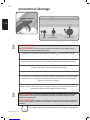
WARNING!
WARNING!
THIS APPLIANCE IS HOT WHEN OPERATING AND CAN CAUSE SEVERE BURNS IF CONTACTED.
• Do not operate appliance before reading and understanding operang instrucons. Failure to operate
appliance according to operang instrucons could cause re or injury.
• Risk of burns. The appliance should be turned o and cooled before servicing.
• Do not install damaged, incomplete or substute components.
• Ensure you have incorporated adequate safety measures to protect infants/toddlers from touching
hot surfaces.
• Under no circumstances should this appliance be modied.
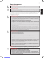
• Keep the packaging material out of reach of children and dispose of the material in a safe manner. As
with all plasc bags, these are not toys and should be kept away from children and infants.
• Do not leave appliance unaended when in use.
• For Outdoor use only.
• This appliance must not be used for cooking.
• This unit is not for use with solid fuel.
• Improper installaon, adjustment, alteraon, service, or maintenance can cause injury or property
damage. Read the installaon, operang and maintenance instrucons thoroughly before installing or
servicing this equipment.
• This appliance shall be used ONLY outdoors in a well-venlated space and shall NOT be used inside a
building, garage, or any other enclosed area.
• Cylinders must be stored outdoors in a well-venlated area out of reach of children. Disconnected
cylinders must have threaded valve plugs ghtly installed and must not be stored in a building, garage
or any other enclosed area.
• Storage of this appliance indoors is permissible only if it has been disconnected from its fuel supply
(natural gas line or LP gas cylinder).
• If it is evident there is excessive abrasion or wear, or the hose is cut, it must be replaced prior to the
appliance being put into operaon.
• Inspect the fuel supply connecon for signs of leakage (including the hose for LP models) before each
use of the appliance.
• The pressure regulator and hose assembly supplied with LP models must be used. Replacement
pressure regulators and hose assemblies must be those specied in this manual.
• The LP gas supply cylinder used with LP models must be constructed and marked in accordance with
the specicaons for LP-gas cylinders as required by the U.S. Department of Transportaon (DOT) or
the Canadian Transport Commission (CTC).
• The LP gas cylinder supply system must be arranged for vapour withdrawal.
• The LP-gas cylinder used must include a collar to protect the cylinder valve.
• When an LP model is not in use, the LP-gas must be turned o at the supply cylinder.
• To extend the life of your appliance, protect and cover it from the elements when not in use.
• This product must be installed by a licensed plumber or gas er when installed within the
commonwealth of Massachuses.

www.napoleongrills.com
4
EN
INPUT
MODEL FUEL ORIFICE SIZE MAX. INPUT Btu/Hr GAS INLET PRESSURES
GSS48 Natural Gas #25 55, 000 7.0” W.C.
GSS48 Propane Gas #43 55, 000 11.0” W.C.
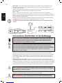
Geng Started
1. Remove all of the parts from the carton. Use the parts list to ensure all necessary parts are included.
2. Do not destroy packaging unl the appliance has been installed and operates to your sasfacon.
3. Choose a locaon that meets the clearance to combusbles as outlined in this manual. Take into consideraon
the need for clear and easy access to the on/o valve AFTER the appliance is installed and connected to the gas
supply in order to safely turn o the burner.
4.
5. Read and follow all instrucons in this manual before installing or servicing this gas appliance.
WARNING!
CAUTION!
This gas appliance was tested and listed to Canadian and American Naonal Standards, ANSI Z21.97-2012/
CSA 2.41-2012 “Standard for Outdoor Decorave Gas Appliance” and CGA 2.17-M91 (R2009) “Gas-Fired
Appliance for use at High Altude” by OMNI-Test Laboratories. When an appliance is for connecon to a
xed piping system, the installaon must conform with local codes, or in the absence of local codes, with
the Naonal Fuel Gas Code, ANSI Z223.1/NFPA 54, Internaonal Fuel Gas Code, Natural Gas and Propane
Installaon Code, CSA B149.1, or Propane Storage and Handling Code, B149.2, as applicable.
The appliance, when installed, must be electrically grounded in accordance with local codes, or in the
absence of local codes, with the Naonal Electrical Code, ANSI/NFPA 70 or the Canadian Electrical Code,
CSA C22.1.
This appliance should be installed and serviced by a qualied installer to conform with local codes.
Installaon pracces vary from region to region and it is important to know the specics that apply to your
area, for example: in Massachuses State:
• The appliance o valve must be a “T” handle gas cock.
• The exible connector must not be longer than 36 inches.
The appliance and its individual shut o valve must be disconnected from the gas supply piping system
during any pressure tesng of the system at test pressures in excess of 1/2 psig (3.5kPa).
This appliance must be isolated from the gas supply piping system by closing its individual manual shut o
valve during any pressure tesng of the gas supply piping system at test pressures equal to or less than
1/2 psig (3.5kPa).
• Always keep the appliance area clear and free
from combusble materials, gasoline, and
other ammable vapours and liquids.
• Do not locate appliance where it can get
excessively wet.
• Do not use this appliance if any part has been
under water. Immediately call a qualied
service technician to inspect the unit and to
replace any part of the control system and any
gas control, which has been underwater.

www.napoleongrills.com
5
EN
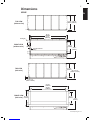
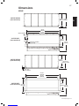
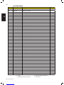
TOP VIEW
TOP VIEW
GSS48
FRONT VIEW
FRONT VIEW

www.napoleongrills.com
6
EN
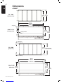
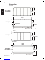
GSS48ST
FRONT VIEW
FRONT VIEW
TOP VIEW
TOP VIEW

www.napoleongrills.com
7
EN
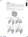
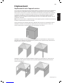
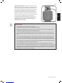
Locang Your Outdoor Appliance
It is important when selecng a locaon for your appliance to ensure clearances to adjacent combusbles
are met. This appliance is intended for installaon on an outdoor pao or in your yard. It is highly
recommended that this appliance be installed in a sheltered area (following the guidelines outlined
below). Direct wind will cause an errac ame and possible pilot or main burner outage. An errac
ame could also lead to excessive carboning (black soot), this condion is not a safety issue but is visually
undesirable.
: When choosing a locaon for your appliance, care must be taken to avoid areas where excessive
moisture or running water may be a problem.
Any enclosure (shelter) in which the appliance is used must comply with one of the following:
With walls on all sides, but at least one permanent opening at ground level and no overhead cover.
Within a paral enclosure which includes an overhead cover and no more than two sidewalls. These
sidewalls may be parallel, as in a breezeway, or at right angles to each other.
Within a paral enclosure which includes an overhead cover and three sidewalls, as long as 30 percent or
more of the horizontal periphery of the enclosure is permanently open.

www.napoleongrills.com
8
EN
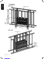
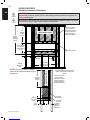
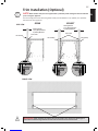
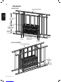
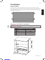
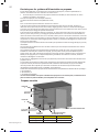
FRONT VIEW
REAR VIEW
2 X 4 STEEL STUDS
36” (914 mm)
minimum
2 X 6 STEEL STUD
1/2” (13 mm) CEMENT BOARD
2 X 4 STEEL STUDS
2 X 6 STEEL STUD
1/2” (13 mm) CEMENT BOARD

www.napoleongrills.com
9
EN
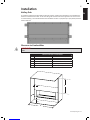
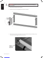
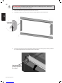
Nailing Tabs
To install the appliance face ush with the nished surface, posion the framework to accommodate the
thickness of the nished surface. Screw the nailing tabs to either side of the appliance and secure to the
2 x 4 steel framing. The tabs will facilitate the installaon of either a 1/2"(13mm) or 3/4”(19mm) nished
surface thickness.
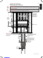
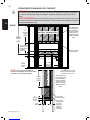
Clearance to Combusbles
WARNING!
Minimum Clearance To Combustibles
Clearance Dimension
A From Ground or other surface 6” (152mm)
B From Sides 6” (152mm)
C From Ceiling 36” (915mm)
D Alcove Width 60” (1524mm) Minimum
E Alcove Depth 24” (610mm) Maximum
A
BC
D
E

www.napoleongrills.com
10
EN
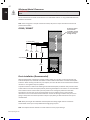
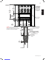
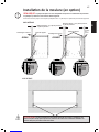
Minimum Enclosure Clearances
WARNING!
WARNING!
GSS48 (ONE SIDED)
NON COMBUSTIBLE
NOTE!
NON COMBUSTIBLE

www.napoleongrills.com
11
EN
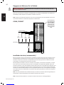
NON COMBUSTIBLE
Minimum Enclosure Clearances
WARNING!
WARNING!
GSS48ST (SEE THROUGH)
NOTE!
NON COMBUSTIBLE

www.napoleongrills.com
12
EN
Minimum Mantel Clearances
WARNING!
We recommend that all mantels are made from non-combusble material. If using combusble materials,
follow the chart below.
: When using paint or lacquer to nish the mantel, the paint or lacquer must be heat resistant to
prevent discolouraon.
GSS48 / GSS48ST
NON COMBUSTIBLE
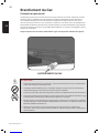
Drain Installaon (Recommended)
Although this replace is designed to operate outdoors safely, rain and other sources of moisture may
enter the replace area, which will cause water to collect inside the base of the unit within the replace
enclosure. When choosing a locaon for your replace, care must be taken to avoid areas where excessive
moisture or running water may be a problem.
To prevent moisture or water from collecng underneath the replace, the builder must provide a means
to drain water from under the replace, before posioning the replace in its locaon. It is recommended
that a sealed corrosion resistant drain pan with provisions for drainage be posioned underneath
the replace. The drain pan can be constructed from corrosion resistant metal, or other suitable
materials such as an ice and water shield membrane. A means of drainage out of the drain pan such as
piping or weep holes must also be provided. A slope of 1/4” (6mm) per foot towards the drain port is
recommended.
: When planning for the installaon of the replace the framing height must be increased to
accommodate a drain pan and any addional drainage piping required.
: The replace must be installed on a level surface to ensure proper drainage.

www.napoleongrills.com
13
EN
NOTE!
The trim is designed to work with facing material that protrude between 1 1/2” (38mm) to 4” (102mm)
from the front of the appliance.
GSS48 GSS48ST
SIDE VIEW
FRONT VIEW
WARNING!

www.napoleongrills.com
14
EN
CAUTION!
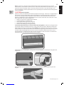
1. Peel protecve coang from front trim pieces.
2. Assemble the trim pieces using (8) #8-32 x 3/8” screws as illustrated.
3. Open the front access door on the appliance and loosen the thumb screws (do not remove). Li up
on the thumb screws and ghten in posion at top of slot.

www.napoleongrills.com
15
EN
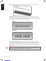
4. Line up the brackets on the trim with the slots on the side of the base and insert as illustrated pushing
unl trim sits ush against front surface. The brackets have been designed with mulple slots (1/4” (6mm)
increments to accommodate dierent nishing materials.
5. Loosen the thumb screw and lower unl it stops. Reghten thumb screw, and close the access door.

www.napoleongrills.com
16
EN
Natural Gas Hook-Up
The gas appliance is designed to operate with natural gas at an inlet pressure of 7 inches water column.
The piping up to the appliance is the responsibility of the installer. A exible metal connector is included
to simplify the installaon of the appliance. Ensure that the connector does not pass through a wall, oor,
ceiling or paron, and is protected from damage. Do not use a hose to connect the appliance. The gas
supply pipe must be suciently sized to supply the BTU/h specied on the rang plate, based on the
length of the piping run.
WARNING!
• Risk of re, explosion or asphyxiaon, ensure there are no ignion sources such as sparks or open
ames.
• The installaon must be performed by a licensed gas er, and all connecons must be leak tested
before operang the appliance.
• All gas connecons must be contained within the appliance when complete.
• High pressure will damage the valve, disconnect gas supply piping before tesng gas line at test
pressures above 1/2 psig.
• Connect the gas supply in accordance to local codes. In the absence of local codes, install to the
current CAN/CSA B149.1 Installaon Code in Canada or to the current Naonal Fuel Gas Code, ANSI
Z223.1/NFPA 54 in the United States
• Leak test all the connecons by brushing on a soap and water soluon. These connecons can be
accessed by removing the burner. (See burner removal instrucons.)
GAS CONNECTION

www.napoleongrills.com
17
EN
Conversion to LP (Propane) Gas
WARNING!
WARNING!
WARNING!
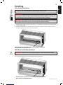
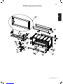
1. Remove the glass embers from the tray.
2. Remove the glass tray from the replace by removing the (8) screws that hold the tray in place.
3. Carefully li the glass tray from the replace and set aside. Take care not to damage or kink the
thermocouple wire.
4. Disconnect the stainless steel ex connector from the orice using (2) wrenches.
5. Unscrew the natural gas orice from the inside of the burner as illustrated.
6. Replace the natural gas orice with the LP (Propane) orice supplied.
: The air shuer has been factory set and does not need to be adjusted.

www.napoleongrills.com
18
EN
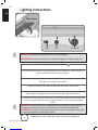
7. Reconnect the stainless steel ex connector to the orice and ghten using (2) wrenches.
8. Place the glass tray over the burner and fasten to the repace with the screws removed in step 2.
9. Fill out the conversion label included with your replace and apply it to the inside of the control panel
access door.
10. A leak test must be performed according to the leak tesng instrucons found in the manual.
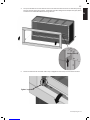
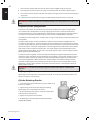
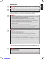
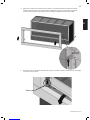
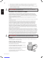
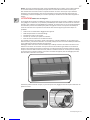
Cylinder Retaining Bracket
1. Fasten the bracket to the boom of the propane bole using
bolt and nut supplied.
2. Tighten the lag screw into the mounng surface leaving
approximately 1/4” of thread above the surface.
3. Slide propane bole into posion so that the bracket slides
under the head of the lag screw.
4. Tighten the lag screw onto the bracket.
5. For fastening to a concrete surface a concrete anchor will be
required. (Not supplied)
WARNING!
Propane Cylinder Specicaons
A dented or rusty cylinder may be hazardous and should be checked by your propane supplier. Never
use a cylinder with a damaged valve. The LP-gas supply cylinder must be constructed and marked in
accordance with the U.S. D.O.T. Specicaons for LP-Gas Cylinders or the Standard for Cylinders, Spheres
and Tubes for Transportaon of Dangerous Good and Commission, CAN/CSA-B339, as applicable.
This appliance has been designed for use with a 20 lb. (9.1 kg) or 30 lb (13.6 kg) size propane cylinder only
(not supplied).
The LP-gas supply cylinder must be provided with a cylinder-connecon device compable with the
connecon for the appliance. The propane cylinder must be provided with a shut-o valve terminang in
a propane cylinder valve type QCC1, and a safety relief device having direct communicaon with the vapor
space of the cylinder. The cylinder supply system must be arranged for vapor withdrawal and the cylinder
shall include a collar to protect the cylinder valve. The LP-gas cylinder must be provided with a listed
overll protecon device (OPD). Do not store a spare LP-gas cylinder under or near this appliance. Never
ll the cylinder beyond 80 percent full.
Use only the pressure regulator and hose assembly provided with this appliance. Replacement pressure
regulators and hose assemblies must be specied by the manufacturer. The regulator supplies a pressure
of 11 inches. water column to the appliance and has a QCC1 type ng. Cylinders to be used with this
unit must be supplied with a QCC1 cylinder valve. A QCC1 cylinder has a posive seang connecon,
which will not allow gas ow unl a posive seal has been achieved. It is also equipped with an excess
ow device. In order to aain full ow to the appliance, the valve must be in the o posion when the
cylinder valve is turned on.
WARNING!
LP (Propane) Gas
Aach cylinder retaining bracket to the base of the cylinder. Then secure to the surface to which it sits.
Cylinder should be on a level surface.

www.napoleongrills.com
19
EN
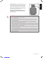
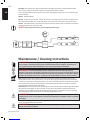
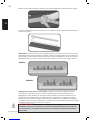
: Ensure the gas regulator hose is kink
free. Remove the cap or plug from the cylinder fuel valve.
Insert the black
QCC1 regulator nipple onto the QCC1 fuel
valve. Hand ghten clock
wise. Do not use tools. Leak test
all joints prior to using the appliance. A leak test must be
performed annually and each me a cylinder is hooked up
or if a part of the gas system is replaced.
CAUTION!
• Make sure cylinder valve is in its full o posion.
(Turn clockwise to stop).
• Check cylinder valve features to ensure it has proper external mang threads. (Cylinder Valve
Marked: USE WITH TYPE 1)
• Inspect hose shipped with the unit for damage. Never aempt to use damaged or plugged
equipment. See your local LP Gas Dealer for repairs.
• When connecng regulator assembly to the cylinder valve, hand ghten black QCC1 nut clockwise
to a posive stop. DO NOT use a wrench to ghten. Use of a wrench may damage the quick closing
coupling nut and result in a hazardous condion.
• Locate the hose out of pathways where people may trip over it or in areas where the hose may be
subject to accidental damage.
• Open cylinder valve fully (counter-clockwise). Turn the on/o valve at the unit slowly to the on posion
and use a soapy water soluon to check all connecons for leaks as indicated in the diagrams before
aempng to light the appliance. If a leak is found, turn tank valve o and do not use the appliance
unl repairs can be made.

www.napoleongrills.com
20
EN
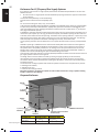
CYLINDER SIZE OPENING A AREA OPENING B AREA
20 lb (9.1kg) 20in2 (130cm2) 10in2 (65cm2)
30 lb (13.6kg) 30in2 (195cm2) 15in2 (100cm2)
MAXIMUM
MAXIMUM
OPENING
A
OPENING
B
MINIMUM
PARTITION TO ISOLATE CYLINDER
FROM APPLIANCE
RECOMMENDED
MAXIMUM
NON LOCKING DOOR
Propane Enclosure
Enclosures For LP (Propane) Gas Supply Systems
If you build an enclosure for an LP gas cylinder, follow these recommended specicaons. You must also
follow local codes.
• An enclosure for an LP-gas cylinder shall be venlated by openings at both the upper and lower levels
of the enclosure.
This shall be accomplished by one of the following:
One side of the enclosure shall be completely open;
OR
For an enclosure having four sides, a top, and a boom:
a) At least two venlaon openings shall be provided in the sidewalls of the enclosure, located within
5 in (127 mm) of the top of the enclosure, equally sized, spaced at a minimum of 90 degrees (1.57
rad), and unobstructed. The opening(s) shall have a total free area of not less than 1 in2 per lb (14.2
cm2 / kg) of stored fuel capacity.
b) Venlaon opening(s) shall be provided at oor level of the enclosure and shall have a total free area of
not less than 1/2 in2 per lb (7.1 cm2 / kg) of stored fuel capacity. If venlaon openings at oor level are in
a side wall, there shall be at least two openings. The boom of the openings shall be 1 in (25.4 mm) or less
from the oor level and the upper edge no more than 5 in (127 mm) above the oor level. The openings
shall be equally sized, spaced at a minimum of 90 degrees (1.57 rad), and unobstructed.
c) Every opening shall have minimum dimensions so as to permit the entrance of a 1/8 inch (3.2mm) diameter
rod.
Venlaon openings in sidewalls shall not communicate directly with other enclosures of the appliance.
Cylinder valves shall be readily accessible for hand operaon. A door on the enclosure to gain access to
the cylinder valve is acceptable, provided it is non-locking and can be opened without the use of tools.
Designs using a cover to gain access to the cylinder and cylinder valve shall be provided with handles or
equivalent at a minimum of 180 degrees apart to facilitate liing of the cover.
There shall be a minimum clearance of 2 inches (50.8mm) between the lower surface of the oor of the LP
gas supply cylinder enclosure and the ground.
The design of the enclosure shall be such that (1) the LP gas supply cylinder(s) can be connected,
disconnected and the connecons inspected and tested outside the cylinder enclosure; and (2) those
connecons which could be disturbed when installing the cylinder(s) in the enclosure can be leak tested
inside the enclosure.
The enclosure for the LP-gas cylinder shall isolate the cylinder from the burner compartment to provide:
a. Shielding from radiaon;
b. A ame barrier; and
c. Protecon from foreign material.
La page est en cours de chargement...
La page est en cours de chargement...
La page est en cours de chargement...
La page est en cours de chargement...
La page est en cours de chargement...
La page est en cours de chargement...
La page est en cours de chargement...
La page est en cours de chargement...
La page est en cours de chargement...
La page est en cours de chargement...
La page est en cours de chargement...
La page est en cours de chargement...
La page est en cours de chargement...
La page est en cours de chargement...
La page est en cours de chargement...
La page est en cours de chargement...
La page est en cours de chargement...
La page est en cours de chargement...
La page est en cours de chargement...
La page est en cours de chargement...
La page est en cours de chargement...
La page est en cours de chargement...
La page est en cours de chargement...
La page est en cours de chargement...
La page est en cours de chargement...
La page est en cours de chargement...
La page est en cours de chargement...
La page est en cours de chargement...
La page est en cours de chargement...
La page est en cours de chargement...
La page est en cours de chargement...
La page est en cours de chargement...
La page est en cours de chargement...
La page est en cours de chargement...
La page est en cours de chargement...
La page est en cours de chargement...
La page est en cours de chargement...
La page est en cours de chargement...
La page est en cours de chargement...
La page est en cours de chargement...
La page est en cours de chargement...
La page est en cours de chargement...
La page est en cours de chargement...
La page est en cours de chargement...
La page est en cours de chargement...
La page est en cours de chargement...
La page est en cours de chargement...
La page est en cours de chargement...
-
 1
1
-
 2
2
-
 3
3
-
 4
4
-
 5
5
-
 6
6
-
 7
7
-
 8
8
-
 9
9
-
 10
10
-
 11
11
-
 12
12
-
 13
13
-
 14
14
-
 15
15
-
 16
16
-
 17
17
-
 18
18
-
 19
19
-
 20
20
-
 21
21
-
 22
22
-
 23
23
-
 24
24
-
 25
25
-
 26
26
-
 27
27
-
 28
28
-
 29
29
-
 30
30
-
 31
31
-
 32
32
-
 33
33
-
 34
34
-
 35
35
-
 36
36
-
 37
37
-
 38
38
-
 39
39
-
 40
40
-
 41
41
-
 42
42
-
 43
43
-
 44
44
-
 45
45
-
 46
46
-
 47
47
-
 48
48
-
 49
49
-
 50
50
-
 51
51
-
 52
52
-
 53
53
-
 54
54
-
 55
55
-
 56
56
-
 57
57
-
 58
58
-
 59
59
-
 60
60
-
 61
61
-
 62
62
-
 63
63
-
 64
64
-
 65
65
-
 66
66
-
 67
67
-
 68
68


NAPOLEON GSS48 Manuel utilisateur
- Catégorie
- Cheminées
- Taper
- Manuel utilisateur
dans d''autres langues
- English: NAPOLEON GSS48 User manual
Documents connexes
-
NAPOLEON GSS48 Le manuel du propriétaire
-
-
-
-
-
-
-