
Sicherheitsschaltgerät
Serien UE 43-6 MF
1.3 Bestimmungsgemäße Verwendung
Bei jeder anderen Verwendung sowie bei
Veränderungen am Gerät oder beim Öffnen
des Gerätes – auch im Rahmen der Monta-
ge und Installation – verfällt jeglicher
Gewährleistungsanspruch gegenüber der
SICK AG.
1.4 Umweltgerechte Entsorgung
Unbrauchbare und irreparable Geräte immer
gemäß den jeweils gültigen landesspezifi-
schen Abfallbeseitigungsvorschriften entsor-
gen. SICK ist gerne bei der Entsorgung der
Geräte behilflich.
2 Produktbeschreibung
2.1 Aufbau und Arbeitsweise des Geräts
Die Eingänge des Sicherheitsschaltgeräts
UE 43-6 MF sind für den Anschluss der un-
ter dem Abschnitt Verwendungsbereiche
des Geräts aufgeführten Befehlsgeber oder
Sicherheitssensoren vorbereitet. Die 6 Frei-
gabestrompfade dienen als sichere Ausgän-
ge. Die Meldestrompfade sind nicht
sicherheitsrelevante Ausgänge.
2.2 Gerätefunktionen
Grundsätzlich verhalten sich Freigabestrom-
pfade (Sicherheitsausgänge) und Meldestrom-
pfade entgegengesetzt: Schließen die
Freigabestrompfade, so öffnen die Melde-
strompfade – und umgekehrt.
Das Betätigen des Sensors bewirkt ein Öff-
nen der Freigabestrompfade. Der manuelle
oder automatische Reset sowie die Schütz-
kontrolle sind je nach Anforderung mittels
externer Beschaltung zu realisieren (siehe
4.2.3 Rücksetzung und 4.2.4 Schütz-
kontrolle).
Querschlusserkennung der Eingänge: Ein
Querschluss wird nur bei zweikanaliger
Beschaltung der Eingangskreise erkannt,
wenn diese mit unterschiedlicher Polarität
beschaltet werden.
Synchronzeitüberwachung: Wenn Ein-
gangskreis 2 spätestens 0,5 s nach Ein-
gangskreis 1 schließt, schließen die
Freigabestrompfade. Schließt Eingangskreis
2 vor Eingangskreis 1, wird keine Synchron-
zeit überwacht und die Freigabestrompfade
schließen (Meldestrompfad öffnet). Diese ist
nur bei automatischem Reset wirksam.
1 Sicherheit
Die Sicherheitsschaltgeräte UE 43-6 MF er-
füllen die sicherheitsspezifischen Anforderun-
gen bis Sicherheitskategorie 4 (EN 954) und
die Anforderungen der Stopp-Kategorie 0
(EN 60 204).
Der angeschlossene Befehlsgeber oder Si-
cherheitssensor und die nachfolgende
Steuerung sowie Verdrahtung und Verlegung
müssen der Steuerungskategorie entspre-
chen.
1.1 Sicherheitsvorschriften
● Die Montage und der elektrische
Anschluss dürfen nur von sachkundigen
Personen ausgeführt werden.
● Für die Verwendung und Installation der
Sicherheitsschaltgeräte sowie für die In-
betriebnahme und wiederkehrende tech-
nische Überprüfung gelten die nationalen
und internationalen Rechtsvorschriften,
insbesondere
- die Maschinenrichtline 98/37/EG
- die Arbeitsmittelbenutzungsrichtlinie
89/655/EWG
- die Niederspannungsrichtlinie
73/23/EWG
- EMV Richtlinie 98/336/EG
- die Sicherheitsvorschriften sowie
- die Unfallverhütungsvorschriften und
Sicherheitsregeln
● Hersteller und Benutzer der Maschine, an
der Schutzeinrichtungen verwendet wer-
den, sind dafür verantwortlich, alle gelten-
den Sicherheitsvorschriften und -regeln
mit der für sie zuständigen Behörde in
eigener Verantwortung abzustimmen und
einzuhalten.
● Die Betriebsanleitung ist unbedingt zu
beachten und aufzubewahren.
● Die Prüfungen sind von Sachkundigen
bzw. von eigens hierzu befugten und be-
auftragten Personen durchzuführen und
in jederzeit nachvollziehbarer Weise zu
dokumentieren.
● Die Betriebsanleitung ist dem Benutzer
der Maschine, an der das Sicherheits-
schaltgerät verwendet wird, zur Verfügung
zu stellen. Der Benutzer der Maschine ist
durch Sachkundige einzuweisen.
1.2 Verwendungsbereich des Geräts
Das Sicherheitsschaltgerät UE 43-6 MF
dient zum Gebrauch an:
● Not-Aus-Schalter (EN 418): ein- oder
zweikanalig
● Sicherheitsverriegelungen (EN 1088):
ein- oder zweikanalig, wie z. B. Schutz-
türen
● Sicherheitsstromkreise nach EN 60 204-1,
wie z. B. bei beweglichen Abdeckungen
SICK AG • Industrial Safety Systems
Sebastian-Kneipp-Str. 1
79183 Waldkirch • www.sick.com
8 009 954/01-12-03 KW/KE
GA-0101
Printed in Germany (01.04)
Alle Rechte und Änderungen vorbehalten
Angegebene Produkteigenschaften und tech-
nische Daten stellen keine Garantieerklärun-
gen dar
Technischen Daten beachten.
Hinweise
● Die Verdrahtung der Schützkontrolle
(EDM) ist im gleichen Schaltschrank mit
dem Sicherheitsschaltgerät auszuführen.
● Um das Verschweißen der Kontakte der
eingebauten Relais zu verhindern, ist
eine Überstromschutzeinrichtung, Kurz-
schlussschutz (Betriebsklasse gG) nach
der entsprechenden Gebrauchskategorie
zu wählen und in die Freigabestrompfade
einzubinden (siehe Technische Daten
und Abb. 2, Sicherung F 2 / F 3 / F 4 / F
5 / F 6 / F 7).
● Bei Anschluss von kapazitiver oder induk-
tiver Last an den Freigabestrompfaden ist
eine Schutzbeschaltung (Funkenlöschung)
vorzusehen. Hierbei ist zu beachten, dass
sich die Ansprechzeiten je nach Art der
Schutzbeschaltung verlängern.
● Die Leitungen der Ein- und Ausgangs-
signale sind außerhalb des Schalt-
schranks entsprechend der anzuwenden-
den Sicherheitskategorie zu verlegen
(EN 954). Z. B. geschützte Verlegung,
Einzelmantelleitung mit Schirm etc.
● Die Angaben in Technischen Daten sind
unbedingt zu beachten.
4.1 Anschlussbelegung
Der Reset ist überwacht. Bei Not-Aus-Anwen-
dung ist manuelle Rücksetzung zu verwen-
den.
Automatische Rücksetzung
Zwischen S 12 - S 34 ist eine Drahtbrücke
anzuschließen. Keine Verbindung zwischen
Y 1 - Y 37.
4.2.4 Schützkontrolle (EDM)
Die Schützkontrolle wird nur beim Rück-
setzen wirksam.
Das Verbinden der Öffnerkontakte der ange-
steuerten Schaltglieder (K
A
bis K
F
) an Y 1 -
Y 2 dient als Schützkontrolle.
Ist keine Schützkontrolle gewünscht, ist zwi-
schen Y 1 und Y 2 eine Brücke zu legen.
4.2.5 Eingangskreise (CH 1, CH 2)
Bevor ein Reset erfolgen kann, müssen die
Eingangskreise geschlossen sein; als Ein-
richtungshilfe melden die LEDs CH 1 und
CH 2 den Status der zugehörigen Eingangs-
kreise. Leuchtet z. B. vor dem manuellen
Reset nur die LED CH 2, ist der Eingangs-
kreis 1 (bei zweikanaligem Anschluss: S 11 -
S 12) zu überprüfen.
5 Inbetriebnahme
Gefahrbereich kontrollieren!
Vor der Inbetriebnahme muss sichergestellt
sein, dass sich niemand im Gefahrbereich
aufhält. Die Sicherheitsvorschriften und Prüf-
hinweise, wie oben beschrieben, sind zu be-
achten.
Folgende Funktionstests sind bei der Inbe-
triebnahme durchzuführen, dabei ist auch die
Funktion der Schützkontrolle zu überprüfen:
5.1 Funktionstest mit manueller
Rücksetzung
Nach Anlegen der Versorgungsspannung (LED
SUPPLY leuchtet) sind die Freigabestrom-
pfade geöffnet (Meldestrompfade geschlos-
sen). Ist der angeschlossene Sensor nicht
betätigt (d. h. Eingangskeise geschlossen,
LEDs CH 1 und CH 2 leuchten), schließen
die Freigabestrompfade bzw. öffnen die
Meldestrompfade nach Betätigen der Rück-
setztaste (LEDs K 1 und K 2 leuchten). Wäh-
rend des Betätigens der Reset-Taste
leuchtet die LED K 3 RESET.
Das Betätigen des Sensors (Öffnen eines
oder beider Eingangkreise) bewirkt ein Öffnen
der Freigabestrompfade und Schließen der
Meldestrompfade (LEDs CH 1, CH 2, K 1,
K 2 aus).
5.2 Funktionstest mit automatischer
Rücksetzung
Nach Anlegen der Versorgungsspannung
(LED SUPPLY leuchtet) bleiben die Freigabe-
strompfade geöffnet (Meldestrompfade ge-
schlossen), bis der Sensor die Eingangs-
kreise schließt (LEDs CH 1 und CH 2 leuch-
ten und K 3 signalisiert ein erfolgreiches
Autoreset mit einem kurzen Aufblinken),
dann schließen die Freigabestrompfade und
die Meldestrompfade öffnen (LEDs K 1 und
K 2 leuchten).
Das Betätigen des Sensors (Öffnen eines
oder beider Eingangskreise) öffnet die
Freigabestrompfade und schließen die
Meldestrompfade (LEDs K 1 und K 2 aus).
Tipp: Die Meldestrompfade 71/72 und 81/
82 sind dem Relais K 1, die Pfade 91/92
und 01/02 dem Relais K 2 zugeordnet. Da-
durch ist eine Fehlerauswertung mit exter-
nen Geräten möglich.
K
E
K
F
S21 S11 S33 Y3
S22 S12
K
D
S37
Y1
Y2
K
B
K
C
K
A
CH2
CH1
Y1
S34
RESET
++–
EDM
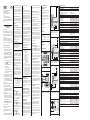
Abb. 3: Beispiel für 1-kanaligen Not-Aus mit ma-
nueller Rücksetzung, Schützkontrolle (EDM)
S21 S11 S33
S22 S12
S37
Y1
Y2
K
E
K
F
K
D
K
B
K
C
K
A
CH2
CH1
Y1
S34
Y3
RESET
EDM
++–
Abb. 4: Beispiel für 2-kanaligen Not-Aus mit manu-
eller Rücksetzung, Schützkontrolle (EDM)
K
E
K
F
S 21 S 11 S33
S34S22 S12
K
D
S37
Y1
Y2
K
B
K
C
K
A
CH2
CH1
Y1
Y3
EDM
+
+–
RESET
Abb. 5: Beispiel für 2-kanalige Schütztür mit Quer-
schlussüberwachung der Eingänge, Schützkontrolle
(EDM)
5.3 Regelmäßige Prüfung der
Schutzeinrichtung durch
Sachkundige
● Anlage entsprechend den national gülti-
gen Vorschriften innerhalb der geforder-
ten Frist prüfen!
● Nach Änderungen an der Maschine oder
Schutzeinrichtung ist die Anlage gemäß
der oben aufgeführten Vorschrift zur Inbe-
triebnahme zu prüfen.
6 Wartung
Die Sicherheitsschaltgeräte UE 43-6 MF ar-
beiten wartungsfrei.
7 Technische Daten
siehe Tabelle
8 Bestelldaten
D
Bezeichnung Farbe Funktion
SUPPLY grün Versorgungspannung aktiv
CH 1 grün Eingangskreis 1 geschlossen
CH 2 grün Eingangskreis 2 geschlossen
K 1 grün Relais K 1 aktiv
K 2 grün Relais K 2 aktiv
K 3 grün Reset-Vorgang
2.3 Anzeigeelemente
3 Montage
Betrieb nur im Schaltschrank!
Das Sicherheitsschaltgerät UE 43-6 MF ist
nur für die Montage im Schaltschrank mit
mindestens der Schutzart IP 54 geeignet.
Die Montage der Geräte erfolgt durch Auf-
schnappen auf eine Tragschiene.
4 Elektroinstallation
Anlage spannungsfrei schalten!
Um bei der Elektroinstallation ein unbeab-
sichtigtes Starten der Anlage bzw. eine elek-
trische Gefährdung auszuschließen, ist die
Anlage spannungsfrei zu schalten.
Berührungsschutz gemäß
EN 50 178 herstellen!
Um einen Berührungsschutz gemäß
EN 50 178 sicherzustellen, Hinweise in
4.2 Betriebsarten
4.2.1 Einkanaliger Betrieb
Das potentialfreie Schaltelement des Sicher-
heitssensors wird zwischen S 11 und S 12
angeschlossen. Zwischen S 12 - Y 3 und
S 21 - S 22 sind Drahtbrücken anzuschlie-
ßen (siehe Abb. 3).
4.2.2 Zweikanaliger Betrieb mit
Querschlusserkennung der Eingänge
Die zwei potentialfreien Schaltelemente des
Sicherheitssensors sind zwischen S 11 -
S 12 bzw. S 21 - S 22 anzuschließen. Zwi-
schen S 33 - Y 3 ist eine Drahtbrücke anzu-
schließen (siehe Abb. 4 und 5).
4.2.3 Rücksetzung
Manuelle Rücksetzung
Für manuelle Rücksetzung ist eine Rücksetz-
taste mit Schließerkontakt zwischen Kon-
takten S 12 und S 34 anzuschließen und
ein Brücke zwischen Y 1 - S 37 zu legen.
Die Rücksetztaste ist außerhalb des Gefahr-
bereichs so zu installieren, dass sie nicht
aus dem Gefahrbereich heraus betätigt wer-
den kann. Außerdem muss der Benutzer
den Gefahrbereich beim Betätigen vollstän-
dig überblicken können.
90
52,5
75
3,8
120,5
107
für Hutschiene EN 50 022
Ausführung Typ Bestell-Nr.
mit Schraubklemmen
24 V DC UE 43-6 MF 2 D 3 6 024 902
120 V AC UE 43-6 MF 2 A 2 6 024 905
230 V AC UE 43-6 MF 2 A 3 6 024 906
A 1 Spannungsversorgung
(DC-Version: + 24 V)
A 2 Spannungsversorgung
(DC-Version: 0 V)
S 11, S 33 + 24 V DC (Steuerspannung)
S 12 + Eingangskreis 1 (K 1)
Y 3 + Eingangskreis 2 (K 2)
S 22 – Eingangskreis 2 (K 2)
S 21 0 V DC (Steuerspannung)
Y 1 - Y 2 Schützkontrolle (EDM)
Y 1 - Y 37 Einstellung der Rücksetzung
gebrückt: manuell
ungebrückt: automatisch
S 12 - S 34 Rücksetzung
13 - 14 Freigabestrompfad 1 (sicherheitsrelevant)
23 - 24 Freigabestrompfad 2 (sicherheitsrelevant)
33 - 34 Freigabestrompfad 3 (sicherheitsrelevant)
43 - 44 Freigabestrompfad 4 (sicherheitsrelevant)
53 - 54 Freigabestrompfad 5 (sicherheitsrelevant)
63 - 64 Freigabestrompfad 6 (sicherheitsrelevant)
71 - 72 Meldestrompfad 1 (nicht sicherheitsrelevant)
81 - 82 Meldestrompfad 2 (nicht sicherheitsrelevant)
91 - 92 Meldestrompfad 3 (nicht sicherheitsrelevant)
01 - 02 Meldestrompfad 4 (nicht sicherheitsrelevant)
9 Anhang
9.1 Zulassungen
BG,
GS,
C
UL
US
9.2 Schaltungsbeispiele
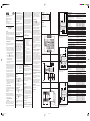
Abb. 2: Basisbeschaltung: Spannungversorgung,
6-kanaliger Ausgangskreis (siehe Technische Da-
ten)
A1 S11 S33 S34 S35 13 23 43
A2 S2 S12 S31 S22 14 24 44
F 2
F 3
S34 Y1 Y2
S22 S12 Y3
UE 43-6 MF
33
34
F 4
F 5
F 6
F 7
53
63
54
64
S33
S11S21
F 1
K
B
K
F
K
E
K
D
K
C
K
A
CH2
CH1
S37
Y1
Abb. 1: Innenbeschaltung UE 43-6 MF
14
13
24
23
34
33
44
43
54
53
64
63
72
71
82
81
92
91
02
01
EDM
RESET
CONTROL-
LOGIC
K 1
K 2
A1
A2
S34
Y1 S37
S12
S11
+
S21
Y2Y1 S22 Y3
A1 S11
S12
S21
S22 S33
S34
Y1 Y2 Y3
13 23
33 43
53 63
71 81 91
01
14 24
3444
54 64
72 82 92 02
Y1
S37
A2
CH 2
CH 1
S33
–
+
Maße in mm
Technische Daten UE 43-6 MF
min. typ. max.
Allgemeine Systemdaten
Spannungsversorgung an A 1 / A 2 bei DC-Geräten
Ausgangsstrompfad > 25 V AC / 60 V DC PELV
Ausgangsstrompfad < 25 V AC / 60 V DC PELV oder SELV
Spannungsversorgung an A 1 / A 2 bei AC-Geräten Schutzleiterklemme verwenden
Sicherheitskategorie EN 954-1 4
Stopp-Kategorie gemäß EN 60 204 0
Versorgungsspannung U
V
(A 1 / A 2)
UE 43-6 MF 2 D 3 19,2 V DC 24 V DC 26,4 V DC
UE 43-6 MF 2 A 2 96 V AC 120 V AC 132,0 V AC
UE 43-6 MF 2 A 3 184 V AC 230 V AC 253,0 V AC
Leistungsaufnahme AC 5,8 W / 5,9 VA
Leistungsaufnahme DC 2,7 W
Restwelligkeit bei DC-Gerät
(innerhalb der Grenzen von U
V
) 2,4 V
SS
Nennfrequenz bei AC-Betrieb 50 Hz 60 Hz
Steuerspannung S 11 und S 33
Steuerspannung 40 V
Sicherung
AC-Geräte kurzschlussfester Transformator
DC-Gerät PTC-Widerstand
Ansprechzeit bei Querschluss (DC-Gerät) 0,5 s
Einschaltzeit nach Querschlusserkennung (DC-Gerät) 2 s
Galvanische Trennung
zwischen A 1 / A 2 und Y 11 - Y 21 - PE nur bei AC-Geräten
Eingangskreise (S 11 - S 12 und Y 3 - S 21, S 22)
Eingangsstrom 100 mA
Rücksetzzeit
manueller Reset 450 ms
automatischer Reset 550 ms
Synchronzeitüberwachung 500 ms
Betätigungsdauer Rücksetztaste 100 ms
Leitungswiderstand am Eingangskreis 30 Ohm
Einschaltzeit nach Anlegen der
Versorgungsspannung (AC-Geräte) 100 ms
Mindestabschaltzeit 500 ms
Ausgangsstrompfade
(13 - 14, 23 - 24, 33 - 34, 43 - 44, 53 - 54, 63 - 64, 71 - 72, 81 - 82, 91 - 92, 01 - 02)
Rückfallverzögerungszeit (K 1 / K 2) 60 ms
Relaiskontakte 6 Freigabestrompfade (Schließer), sicherheitsrelevant
4 Meldestrompfade (Öffner), nicht sicherheitsrelevant
Kontaktart zwangsgeführt
Kontaktwerkstoff Ag-Legierung; vergoldet
Kontaktbelastbarkeit
Schaltspannung 10 V AC/DC 230 V AC / 30 V DC
Schaltstrom 10 mA 6 A
Summenstrom 24 A
Gebrauchskategorie nach EN 60 947-5-1 AC-15 Ue 230 V AC, I
e
3 A (3600 Sch/h)
DC-13 Ue 24 V DC, I
e
2 A (3600 Sch/h)
Zulässige Schalthäufigkeit 3600 Sch/h
Lebensdauer, mech. (Schaltspiele) 1 × 10
7
Elektrische Lebensdauer (abhängig von der Belastung) 1 × 10
5
Betriebsdaten
Bemessungsstoßspannung (U
Imp.
)4 kV
Überspannungskategorie III
Verschmutzungsgrad des Gerätes (EN 50 178)
außen 3
innen 2
Bemessungsspannung 300 V AC
Prüfspannung U
eff
(50 Hz) EN 60 439-1 2,0 kV
Schutzart
Gehäuse IP 40
Klemmen IP 20
Störaussendung EN 60 947-1 02/99
Störfestigkeit EN 60 947-1 02/99
Betriebsumgebungstemperatur – 25 °C +55 °C
Lagertemperatur – 25 °C +75 °C
Anschlussquerschnitte
Eindraht (2 x, gleicher Querschnitt) 0,75 mm
2
2,5 mm
2
Eindraht (1 x) 0,75 mm
2
2,5 mm
2
feindrahtig mit Aderendhülsen (2 x, gleicher Querschnitt) 0,5 mm
2
1,5 mm
2
feindrahtig mit Aderendhülsen (1 x) 0,5 mm
2
1,5 mm
2
Masse 0,8 kg

UE 43-6 MF Series
Safety Relay
AG shall become null and void.
1.4 Environmentally correct disposal
Unusable and irreparable units should al-
ways be disposed of in accordance with the
applicable waste disposal regulations speci-
fic to the country concerned. SICK will be
pleased to assist in disposing of units.
2 Product description
2.1 Construction and operation of the
unit
The Inputs of the UE 43-6 MF Safety Relay
have been designed for connection to the
respective safety sensors mentioned in the
Section entitled “Areas of application”. The
normally open output circuits serve as
safety relevant outputs. The signal circuits
are non safety relevant output circuits.
2.2 Functions of the units
Safety outputs and signal outputs have
opposite logic. When the safety outputs close,
the signal output opens.
Actuating the sensor causes the safety
outputs to open. Manual or automatic Reset
and EDM are implemented by means of
external switching, depending on application
(see 4.2.3 Reset and 4.2.4 EDM).
Short circuit detection of the input
circuits: A short circuit can be detected
using dual-channel switching of the input
circuits when these are switched with
opposing polarities (Fig. 4 and 5).
Monitoring of synchronisation: Upon
activating the input circuits, synchronisation
is monitored. Only if input 2 closes by no
later than 0,5 sec after input 1 do the
output circuits close. If input 2 closes before
input 1, the monitoring of synchronisation
will not be effected, and the safety output
circuits will close (the signal circuits are thus
opened). This is only active in automatic
reset.
1 Safety
The UE 43-6 MF Safety Relays meet safety-
related requirements up to Safety Category
4 (EN 954) and including Stop Category 0
(EN 60 204).
The wires for the input and output signals
shall be routed outside the control cabinet,
according to the safety category to be used.
1.1 Safety regulations
● Assembly and electrical connection must
only be carried out by competent per-
sons.
● The national and international legal provi-
sions apply to the use and installation of
safety relays as well as to commissioning
and routine technical checks, in particular
- the Machinery Directive 98/37/EEC
- the Provision and Use of Work
Equipment Regulation 89/655/EEC
- the Low Voltage Directive 73/23/EEC
- the EMC Directive 98/336/EEC
- the Safety Regulations, plus
- the Accident Prevention Regulations
and Safety Rules
● Manufacturers and users of the machine,
on which the safety devices are used, are
responsible for agreeing all current safety
regulations and rules with their compe-
tent authority, and for observing them.
● The operating instructions are to be hee-
ded and kept for future reference.
● The tests shall be carried out by compe-
tent persons or by persons specifically
authorised and instructed, and they shall
be documented so as they are traceable
at any time.
● The operating instructions shall be made
available to the user of the machine on
which the safety relay is used. The user
of the machine shall be instructed by
competent persons.
1.2 Areas of application
The UE 43-6 MF Safety Relay is intended
for use on safety sensors with potential free
contacts, such as:
● Emergency Stops (EN 418): single- or
dual-channel
● Safety interlocks (EN 1088): single- or
dual-channel, such as safety doors.
● Safety circuits as per EN 60 204-1, such
as with movable guards.
1.3 Use in accordance with the
regulations
For any other use, and in the event of modi-
fications to the unit, or if the unit has been
opened, even as part of assembly and in-
stallation, any warranty claims against SICK
SICK AG • Industrial Safety Systems
Sebastian-Kneipp-Str. 1
79183 Waldkirch • www.sick.com
8 009 954/01-12-03 KW/KE
GA-0101
Printed in Germany (01.04)
All rights reserved
Subject to change without prior notice
protection device (short-circuit protection
(Operating Class gG)) should be selected
according to the appropriate utilisation
category and incorporated into the output
paths (see Technical Data and fig. 2,
fuse F 2 / F 3 F 4 / F 5 / F 6 / F 7).
● If capacitive or inductive loads are con-
nected to the output circuits, a protective
circuit (spark suppression) shall be pro-
vided. In doing so, it shall be observed
that the response times increase
depending on the type of protection.
● The wires for the input and output signals
shall be routed outside the control
cabinet, according to the safety category
to be used (EN 954). For example,
protected routing, shielded cabling etc.
● The details given in Technical Data must
be observed.
4.1 Wiring of connections
Connecting the normally closed contacts of
the external relays with Y 1 - Y 2 ensures
static monitoring of the contactors.
When no external device monitoring is
wanted a jumper is to be made between
Y 1 - Y 2.
5 Commissioning
Monitor the danger zone!
Prior to commissioning, it must be ensured
that nobody is in the danger zone. The
safety regulations and test instructions as
described above are to be heeded.
The following functional tests/checks are to
be carried out during commissioning:
5.1 Manual reset, functional testing
After applying the supply voltage (LED
SUPPLY illuminates), the normally open
outputs are opened. If the connected sensor
is not activated (i. e. the input circuits are
closed), the LEDs CH 1 and CH 2 illuminate.
The safety outputs close, and the signal
circuits open after the reset button is
activated (LED K 1 and K 2 illuminate).
While the rest button is being pressed, LED
K 3 illuminates.
Activation of the sensor (opening of one or
both input circuits) initiates the opening of
the six safety outputs and the closing of the
signal circuits (LEDs CH 1, CH 2, K 1 and
K 2 extinguished).
5.2 Automatic reset, functional testing
After applying the supply voltage (LED
SUPPLY illuminates), the safety outputs
remain open until the sensor closes the
input circuits (LEDs CH 1 and CH 2
illuminate and K 3 signalises a successful
Auto Reset with a short blinking). The safety
output circuits then close and the signal
circuit opens (LED K 1 and K 2 illuminate).
Activation of the sensor (opening of one or
both input circuits) opens the six safety
output circuits and closes the signal circuits
(LED K 1 and K 2 extinguished).
Tip: The signal circuit 71/72 is related to K
1 and 81/82 is related to K 2. These
outputs can be used to gauge the correct
working function of the unit.
5.3 Regular inspection / testing of the
safety equipment by trained technical
personnel
● Test the system within the specified
period in accordance with current natio-
nal regulations!
● Following modifications to the machine or
the safety device, the system shall be
examined in accordance with the
commissioning specification given above.
6 Maintenance
In operation, the UE 43-6 MF Safety Relay
is maintenance-free.
7 Technical data
see Table
Description Colour Function
SUPPLY Green Supply voltage present
CH 1 Green Input Circuit 1 closed
CH 2 Green Input Circuit 2 closed
K 1 Green Relay K 1 energised
K 2 Green Relay K 2 energised
K 3 Green Resetting
GB
A 1 Voltage supply (DC-version: + 24 V)
A 2 Voltage supply (DC-version: 0 V)
S 11, S 33 + 24 V DC (control voltage)
S 12 + Input circuit 1 (K 1)
Y 3 + Input circuit 2 (K 2)
S 22 – Input circuit 2 (K 2)
S 21 0 V DC (control voltage)
Y 1 - Y 2 External Device Monitoring (EDM)
Y 1 - Y 37 Reset
Jumpered: manual
Not jumpered: automatic
S 12 - S 34 Reset
13 - 14 Output circuit 1 (safety relevant)
23 - 24 Output circuit 2 (safety relevant)
33 - 34 Output circuit 3 (safety relevant)
43 - 44 Output circuit 4 (safety relevant)
53 - 54 Output circuit 5 (safety relevant)
63 - 64 Output circuit 6 (safety relevant)
71 - 72 Signal circuit 1 (non safety relevant)
81 - 82 Signal circuit 2 (non safety relevant)
91 - 92 Signal circuit 3 (non safety relevant)
01 - 02 Signal circuit 4 (non safety relevant)
4.2 Operating modes
4.2.1 Single-channel operation
The safety sensor is connected between
S 11 and S 12. S 12 - Y 3 and S 21 - S 22
must be jumpered (see fig. 3).
4.2.2 Dual-channel operation with short
circuit detection of the input
circuits
The potential free outputs of the safety
sensor are to be connected between S 11 -
S 12 and S 21 - S 22. S 33 - Y 3 must be
jumpered(see fig. 4 and 5).
4.2.3 Reset
Manual reset
For manual reset a reset button having a
normally open contact is wired between
contacts S 12 and S 34. Y 1 - S 37 must be
jumpered.
The reset button is to be installed outside
the danger zone in such a manner that it
cannot be activated from within the danger
zone. In addition, the operator must have
full visual command of the danger zone.
This Reset is monitored.
Where Emergency Stop is activated, manual
Reset must be used.
Automatic reset
S 12 - S 34 must be jumpered. No jumper
between Y 1 - Y 37.
4.2.4 External device monitoring (EDM)
This is only effective during Reset.
Version Type Order No.
With screw terminals
24 V DC UE 43-6 MF 2 D 3 6 024 902
120 V AC UE 43-6 MF 2 A 2 6 024 905
230 V AC UE 43-6 MF 2 A 3 6 024 906
Fig. 3: Example connection of a UE 43-6 MF with
single-channel emergency stop with manual reset,
external device monitoring
Fig. 4: Example connection of a UE 43-6 MF with
dual-channel emergency stop, manual reset,
external device monitoring
K
E
K
F
S 21 S 11 S33
S34S22 S12
K
D
S37
Y1
Y2
K
B
K
C
K
A
CH2
CH1
Y1
Y3
EDM
+
+–
RESET
Fig. 5: Example connection of a UE 43-6 MF with
dual-channel safety door with short circuit detection
of the input circuits, external device monitoring
Fig. 2: Basic wiring: voltage supply, 6 output circuits (see Technical Data)
A1 S11 S33 S34 S35 13 23 43
A2 S2 S12 S31 S22 14 24 44
F 2
F 3
S34 Y1 Y2
S22 S12 Y3
UE 43-6 MF
33
34
F 4
F 5
F 6
F 7
53
63
54
64
S33
S11S21
F 1
K
B
K
F
K
E
K
D
K
C
K
A
CH2
CH1
S37
Y1
2.3 Indicators
3 Assembly
Control cabinet installation only!
The UE 43-6 MF Safety Relay is only
suitable for installation into control cabinets
having a minimum protective type of
enclosure to Class IP 54.
Installation of the units is made by snap-
clipping on to a mounting rail.
4 Electrical installation
Isolate the system!
The system shall be isolated, to prevent any
inadvertent system startup or electrical
hazard.
Contact protection to EN 50 178
To ensure contact protection to EN 50 178,
observe notes in Technical Data.
Instructions
● Wiring of the external device monitoring
(EDM) shall be performed in the same
control cabinet.
● To prevent the contacts of the final
switching relays welding, an overcurrent
Fig. 1: Internal wiring UE 43-6 MF
14
13
24
23
34
33
44
43
54
53
64
63
72
71
82
81
92
91
02
01
EDM
RESET
CONTROL-
LOGIC
K 1
K 2
A1
A2
S34
Y1 S37
S12
S11
+
S21
Y2Y1
S22 Y3
A1 S11
S12
S
21
S22 S33
S34
Y
1
Y
2
Y
3
13 23
33 43
53 63
71 81 91
01
14 24
3444
54 64
72 82 92 02
Y1
S37
A
2
CH 2
CH 1
S33
–
+
90
52.5
75
3,8
120.5
107
for mounting rail EN 50 022
K
E
K
F
S21 S11 S33 Y3
S22 S12
K
D
S37
Y1
Y2
K
B
K
C
K
A
CH2
CH1
Y1
S34
RESET
++–
EDM
S21 S11 S33
S22 S12
S37
Y1
Y2
K
E
K
F
K
D
K
B
K
C
K
A
CH2
CH1
Y1
S34
Y3
RESET
EDM
++–
Dimensions in mm
Technical Data UE 43-6 MF
min. typ. max.
General System Data
Voltage supply to A 1 / A 2 with DC-units
Output circuit > 25 V AC / 60 V DC PELV to A 1 / A 2
Output circuit < 25 V AC / 60 V DC PELV or SELV to A 1 / A 2
Voltage supply to A 1 / A 2 with AC units Use terminal for non-fused earth conductor
Safety category EN 954-1 4
Stop category EN 60 204-1 0
Supply voltage V
S
(A 1 / A 2)
UE 43-6 MF 2 D 3 19.2 V DC 24 V DC 26.4 V DC
UE 43-6 MF 2 A 2 96 V AC 120 V AC 132.0 V AC
UE 43-6 MF 2 A 3 184 V AC 230 V AC 253.0 V AC
Power consumption (AC units) 5.8 W / 5.9 VA
Power consumption (DC unit) 2.7 W
AC Ripple during DC operation
(within the limits of V
S
)2,4 V
PP
Nominal frequency during AC operation 50 Hz 60 Hz
Control voltage for S 11 and S 33
Control voltage 40 V
Fuses
AC units short-circuit proof transformer
DC units PTC resistance
Response time for short circuit 0,5 s
Activation time upon detection of
short circuit (DC unit) 2 s
Electrical separation
between A 1 / A 2 and S 11 - S 21 - PE AC units only
Input circuits (S 11 - S 12 and Y 3 - S 21, S 22)
Input current 100 mA
Reset time
Manual Reset 450 ms
Automatic Reset 550 ms
Synchronisation time (Concurrence Monitoring) 500 ms
Activation period for reset button 100 ms
Line resistance at inputs 30 Ohm
Activation time after application of
supply voltage (AC units) 100 ms
Minimum switch-off time 500 ms
Output circuits
(13 - 14, 23 - 24, 33 - 34, 43 - 44, 53 - 54, 63 - 64, 71 - 72, 81 - 82, 91 - 92, 01 - 02)
Response time 60 ms
Relay contacts 6 Output circuits (NO), safety relevant
4 Signal circuits (NC), non safety relevant
Contact type positively guided
Contact material Silver alloy, gold-plated
Load capability of contacts
Switching voltage 10 V AC/DC 230 V AC / 30 V DC
Switching current 10 mA 6 A
Total switching current 24 A
Application category to EN 60 947-5-1 AC-15 Ue 230 V AC, I
e
3 A (3600 c/h)
DC-13 Ue 24 V DC, I
e
2 A (3600 c/h)
Permitted switching frequency 3600 c/h
Service life, mechanical (switch cycles) 1 × 10
7
Electrical service life (depending on the load) 1 × 10
5
Operational data
Measured transient/surge voltage (V
Imp.
)4 kV
Overload voltage category III
Contamination rating of the unit (EN 50 178)
external 3
internal 2
Measured voltage 300 V AC
Test voltage V
eff
(50 Hz) EN 60 439-1 2.0 kV
Type of protective enclosure
Housing IP 40
Terminals IP 20
Interference emission to EN 60 947-1 02/99
Noise attenuation to EN 60 947-1 02/99
Ambient operating temperature – 25 °C +55 °C
Storage temperature – 25 °C +75 °C
Cross-sections of connections
Solid core wire (2 x, identical cross section) 0.75 mm
2
2.5 mm
2
Solid core wire (1 x) 0.75 mm
2
2.5 mm
2
Fine multi-stranded flex with terminal sleeves
(2 x identical cross section) 0.5 mm
2
1.5 mm
2
Fine multi-stranded flex with terminal sleeves (1 x) 0.5 mm
2
1.5 mm
2
Weight 0.8 kg
8 Ordering data
9 Appendix
9.1 Approvals
BG,
C
UL
US
, GS
9.2 Examples of circuits
UE43_6_M_GB_5.p65 12.02.04, 13:421

Relais de sécurité
Série UE 43-6 MF
1.3 Utilisation conforme aux
dispositions légales
SICK AG ne peut garantir le fonctionnement
dans les spécifications pour tout autre
utilisation ainsi que dans le cas de
modification ou ouverture de l’appareil, y
compris dans le cadre du montage et de
l’installation.
1.4 Mise au rebut dans le respect de
l’environnement
Les appareils inutilisables ou irréparables
doivent être éliminés dans le respect des
prescriptions de mise en décharge légales
en vigueur dans le pays d’utilisation. SICK
donne touts les conseils et informations
utiles pour la mise au rebut de l’appareil.
2 Description du produit
2.1 Construction et Mode de
fonctionnement de l'appareil
Les entrées des relais de sécurité
UE 43-6 MF sont destinées à être
raccordées aux capteurs de sécurité décrits
au paragraphe Domaine d’utilisation de
l’appareil. Deux circuits d’entrée séparés
commandent les relais internes. Les
contacts de commande sont des sorties de
sécurité. Les contacts d’état ne constitue
pas des sorties de sécurité.
2.2 Fonctionnalités
Les contacts de commande ont un fonctionnement
inverse de celui des contacts d’état. Les contacts
de commande se ferment tandis que les contacts
d’état et de retour s’ouvrent.
L'activation du capteur entraîne l'ouverture
des contacts de commande. Si l'application
l'exige, la réinitialisation manuelle ou
automatique ainsi que le contrôle des
contacteurs commandés sont réalisés de
façon externe (cf. 4.2.3 Réarmement et
4.2.4 Contrôle des contacteurs
commandés).
Détection des courts-circuits des entrées :
Un court-circuit peut être détecté en mode
d'entrée à deux voies à condition que la
commande se fasse en polarité inversée (cf.
fig. 4 et 5).
Surveillance de synchronisation : Au
moment de l’activation du circuit d’entrée,
une temporisation est déclenchée. Le se-
cond circuit d’entrée dispose de 0,5
secondes au plus pour se déclencher à son
tour et entraîner la fermeture des contacts
de commande. Si le circuit d’entrée 2 se
ferme avant le circuit d’entrée 1, il n’y a pas
de surveillance de synchronisation et les
contacts de commande se ferment (le
contact d'état s’ouvre). Seulement avec
réarmement automatique.
2.3 Témoins d’état
1 Sécurité
Les relais de sécurité UE 43-6 MF sont con-
formes aux exigences de sécurité de la ca-
tégorie 4 (EN 954) et pour l'arrêt de
catégorie 0 (EN 60 204).
La commande de réarmement raccordée et
la commande aval ainsi que le câblage du
point de vue schéma comme du point de
vue réalisation doivent être conformes à la
catégorie de la commande.
1.1 Prescriptions de sécurité
● Le montage et le raccordement électrique
doivent être effectués par un personnel
habilité.
● Les réglementations de sécurité nationa-
les et internationales sont applicables
pour la mise en service et l’utilisation et
les contrôles périodiques des relais de
sécurité, en particulier :
- la directive machine 98/37 CE
- la directive d’utilisation des outils de
travail 89/655 CEE
- la directive basse tension
73/23 CEE
- la directive CEM 98/336/EEC
- les consignes de sécurité
- les prescriptions de prévention des
accidents et les règles de sécurité
● Le fabricant et l’exploitant de la machine
pourvue d’équipements de protection
sont responsables avec l’Autorité
compétente du respect et de la mise en
oeuvre des prescriptions et des règles de
sécurité en vigueur.
● Cette notice d'instructions doit impérati-
vement être observée et conservée en
vue de son utilisation ultérieure.
● Les contrôles doivent être effectués par
un personnel habilité ou un personnel
spécialement autorisé et mandaté à cet
effet et doivent être systématiquement
documentés de manière compréhensible.
● La notice d’instructions de l’équipement
de protection doit être mise à la disposi-
tion de l’opérateur de la machine sur
laquelle il est monté. L’opérateur de la
machine doit être formé par le personnel
compétent.
1.2 Domaine d’utilisation de l’appareil
Le relais de sécurité UE 43-6 MF est utilisé
exclusivement avec des sorties sans poten-
tiel de capteurs de sécurité par ex. :
● Commutateur d’arrêt d’urgence (EN 418) :
une ou deux voies
● Relais de sécurité à verrouillage (EN
1088) : une ou deux voies par ex. une
protection d’accès
● Circuit d’interverrouillage de sécurité
selon EN 60 204-1, par ex. protecteurs
mobiles
SICK AG • Industrial Safety Systems
Sebastian-Kneipp-Str. 1
D-79183 Waldkirch • www.sick.com
8 009 954/01-12-03 KW/KE
GA-0101
Imprimé en Allemagne (01.04)
Tous droits rérservés, modifications sans
préavis
4 Installation électrique
Effectuer de câblage hors tension
Pour éviter le démarrage inopiné involon-
taire de l’installation et éliminer le risque
d’électrocution, le câblage doit être effectué
hors tension.
Protection contre les manipulations EN
50 178
Pour garantir une protection contre les
manipulations selon EN 50 178, observer
les conseils donnés dans les caractéris-
tiques techniques.
Conseil
● Le câblage des contacteurs commandés
(EDM) doit être effectué dans la même
enceinte que le relais de sécurité.
● Pour prévenir le collage par soudure
électrique des contacts du relais, prévoir
en série avec chaque contact de
commande le montage d’une protection
contre les surintensités, les courts-circuits
(de classe gG, voir aussi les caractéris-
tiques techniques et cf. fig. 2, fusibles F
2 / F 3 / F 4 / F 5 / F 6 / F 7).
● Pour le raccordement d’une charge
capacitive ou inductive sur les contacts
de commande, il est nécessaire de
prévoir un antiparasitage. Observer que
ces équipements selon leur nature
augmentent plus ou moins le temps de
réponse.
● Les câbles de liaison des signaux
d’entrée et de sortie se trouvant en
dehors du boîtier de montage doivent
être posés en conformité avec la
catégorie du risque (EN 954) concerné.
P. ex. câblage protégé, isolation simple
avec blindage, etc.
● Les données des caractéristiques
techniques doivent impérativement être
respectées.
4.1 Câblage des liaisons
4.2.3 Réarmement
Réarmement manuel
Câbler le poussoir de réarmement avec
contact normalement ouvert entre les
bornes S 12 et S 34.
Câbler un cavalier entre les bornes Y 1 &
S 37.
Le poussoir de réarmement doit être installé
à l’extérieur de la zone dangereuse de
manière qu’il soit impossible de l’actionner
depuis la zone dangereuse. L’opérateur doit
voir la zone dangereuse toute entière lors-
qu’il actionne le poussoir de réarmement.
L'entrée de réarmement est surveillée.
Pour une application en arrêt d'urgence, le
réarmement doit être manuel.
Réarmement automatique :
Câbler un cavalier entre les bornes S 12 &
S 34. Ne pas relier Y1 avec Y 37.
4.2.4 Contrôle des contacteurs
commandés
Le contrôle des contacteurs commandés est
activé uniquement au moment du réarme-
ment.
Pour le contrôle du contacteur commandé,
relier le contact NC de l’élément de contact
commandé avec Y 1 - Y 2.
Pour ne pas exploiter le contrôle des
contateurs commandés, relier Y 1 avec Y 2.
5 Mise en service
Danger : Contrôler la zone dangereuse
Avant la mise en service, il doit être établi
que personne ne séjourne à l’intérieur de la
zone dangereuse. Observer les prescriptions
de sécurité et conseils de contrôles décrits
ci-dessus.
La mise en service doit comporter les tests
fonctionnels ci-après, et également une
vérification du fonctionnement des contac-
teurs commandés :
5.1 Test fonctionnel en réarmement
manuel
Après avoir mis l’appareil sous tension, la
LED d’alimentation est allumée, les contacts
de commande sont ouverts (le contact
d’état est fermé). Si le capteur raccordé ne
fonctionne pas (c.-à-d. si les circuits d’entrée
sont fermés) LED CH 1 et CH 2 s’allument.
Les contacts de commande se ferment et
les contacts d’état s’ouvrent lorsque l’on
agit sur le poussoir de réarmement ; les LED
K 1 et K 2 s’allument. Pendant que le
poussoir de réarmement est actionné, la
LED K 3 RESET s’allume.
Une action sur le capteur (ouverture de l’un
ou des deux circuits d’entrée) entraîne
l’ouverture des contacts de commande et la
fermeture des contacts d’état ; les LED CH
1, CH 2, K 1 et K 2 s’éteignent.
5.2 Test fonctionnel en réarmement
automatique
Après avoir mis l’appareil sous tension, la
LED d’alimentation est allumée, les deux
contacts de commande restent ouverts
jusqu’à ce que le capteur raccordé ferme les
circuits d’entrée (LED CH 1 et CH 2
s'allument, les contacts de commande se
ferment et les contacts d’état s’ouvrent ; les
LED K 1 et K 2 s’allument.
Une action sur le capteur (ouverture de l’un
ou des deux circuits d’entrée) entraîne
l’ouverture des contacts de commande et la
fermeture des contacts d’état ; les LED K 1
et K 2 s’éteignent.
K
E
K
F
S21 S11 S33 Y3
S22 S12
K
D
S37
Y1
Y2
K
B
K
C
K
A
CH2
CH1
Y1
S34
RESET
++–
EDM
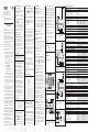
Fig. 3 : Arrêt d’urgence monovoie avec réarmement
manuel et contrôle des contacteurs commandés
S21 S11 S33
S22 S12
S37
Y1
Y2
K
E
K
F
K
D
K
B
K
C
K
A
CH2
CH1
Y1
S34
Y3
RESET
EDM
++–
Fig. 4 : Arrêt d’urgence redondant (2 voies), avec
réarmement manuel et contrôle des contacteurs
commandés
K
E
K
F
S 21 S 11 S33
S34S22 S12
K
D
S37
Y1
Y2
K
B
K
C
K
A
CH2
CH1
Y1
Y3
EDM
+
+–
RESET
Fig. 5 : Protection d’accès redondante (2 voies), avec
surveillance des courts-circuits des entrées et
contrôle des contacteurs commandés
Conseil : le circuit d’état 71/72 est atribué
au relais K 1, le circuit 91/92 au relais K 2.
Une erreur de prise en compte des signaux
d’un appareil externe est donc possible.
5.3 Contrôle régulier de l’équipement de
protection par le personnel habilité
● Un contrôle périodique doit être effectué
dans les temps prescrits par les
réglementations nationales.
● En cas de modification de la machine ou
de l’équipement de protection,
l’installation doit être recontrôlée selon
les prescriptions applicables à la mise en
service.
6 Maintenance
Les relais de sécurité UE 43-6 MF ne
nécessitent aucune maintenance.
7 Caractéristiques techniques
Voir le tableau
8 Références
F
Description Couleur Fonction
SUPPLY vert L’appareil est sous tension
CH 1 vert Circuit d'entrée 1 fermé
CH 2 vert Circuit d'entrée 2 fermé
K 1 vert Relais K 1 activé
K 2 vert Relais K 2 activé
K 3 vert Relais K 3 activé
3 Montage
Danger : Utilisation uniquement en
armoire électrique
Les relais de sécurité UE 43-3 MF sont
destinés au montage dans les armoires
électriques dont l’indice de protection est au
moins de IP 54.
Le montage des appareils se fait par clip-
sage sur un rail profilé de support TS 35
(EN 50 022).
4.2 Modes de fonctionnement
4.2.1 Fonctionnement monovoie
Câbler le capteur de sécurité entre les
bornes S 11 et S 12. Câbler un cavalier
entre les bornes S 12 & Y 3 et S 21 &
S 22 (cf. fig. 3).
4.2.2 Fonctionnement redondant (2
voies) avec détection des courts-circuits
des entrées
Les deux éléments de commutation (libres
de potentiel) du capteur de sécurité doivent
être respectivement raccordés sur S 11 &
S 12 et S 21 & S 22. Câbler un cavalier
entre les bornes S 33 & Y 3 (cf. fig. 4 et 5).
90
52,5
75
3,8
120,5
107
pour rail profilé EN 50 022
Fig. 1 : Schéma interne UE 43-6 MF
14
13
24
23
34
33
44
43
54
53
64
63
72
71
82
81
92
91
02
01
EDM
RESET
CONTROL-
LOGIC
K 1
K 2
A1
A2
S34
Y1 S37
S12
S11
+
S21Y2Y1
S22 Y3
A1 S11
S12
S
21
S22 S33
S34
Y
1
Y
2
Y
3
13 23
33 43
53 63
71 81 91
01
14 24
3444
54 64
72 82 92 02
Y1
S37
A
2
CH 2
CH 1
S33
–
+
Fig. 2 : Schéma de base : alimentation, circuit de
sortie à 6 voies redondantes (cf. caractéristiques
techniques)
A1 S11 S33 S34 S35 13 23 43
A2 S2 S12 S31 S22 14 24 44
F 2
F 3
S34 Y1 Y2
S22 S12 Y3
UE 43-6 MF
33
34
F 4
F 5
F 6
F 7
53
63
54
64
S33
S11S21
F 1
K
B
K
F
K
E
K
D
K
C
K
A
CH2
CH1
S37
Y1
Version Type Référence
avec bornes à vis
24 V CC UE 43-6 MF 2 D 3 6 024 902
120 V CA UE 43-6 MF 2 A 2 6 024 905
230 V CA UE 43-6 MF 2 A 3 6 024 906
9 Annexe
9.1 Homologations
BG,
C
UL
US
, GS
9.2 Exemples de câblage
A 1 Tension d’alimentation (appareil CC : + 24 V)
A 2 Tension d’alimentation (appareil CC : 0 V)
S 11, S 33 + 24 V CC (tension de commande)
S 12 + circuit d’entrée 1 (K 1)
Y 3 + circuit d’entrée 2 (K 2)
S 22 – circuit d’entrée 2 (K 2)
S 21 0 V CC (tension de commande)
Y 1 - Y 2 Contrôle des contacteurs commandés
Y 1 - Y 37 Réarmement
bornes reliées: manuel
bornes non reliées: automatique
S 12 - S 34 Réarmement
13 - 14 Contact de commande 1 (contact de sécurité)
23 - 24 Contact de commande 2 (contact de sécurité)
33 - 34 Contact de commande 3 (contact de sécurité)
43 - 44 Contact de commande 4 (contact de sécurité)
53 - 54 Contact de commande 5 (contact de sécurité)
63 - 64 Contact de commande 6 (contact de sécurité)
71 - 72 Contact d’état 1 (n’est pas un contact de sécurité)
81 - 82 Contact d’état 2 (n’est pas un contact de sécurité)
91 - 92 Contact d’état 3 (n’est pas un contact de sécurité)
01 - 02 Contact d’état 4 (n’est pas un contact de sécurité)
Caractéristiques techniques UE 43-6 MF
min. typ. max.
Caractéristiques communes
Alimentation sur A 1 / A 2 av. appareils CC
circuit de sortie > 25 V CA / 60 V CC PELV
circuit de sortie < 25 V CA / 60 V CC PELV ou SELV
Alimentation sur A 1 / A 2 av. appareils CA utiliser la borne de terre de protection
Catégorie de risque selon EN 954-1 4
Catégorie d'arrêt selon EN 60 204-1 0
Tension d'alimentation U
V
(A 1 / A 2)
UE 43-6 MF 2 D 3 19,2 V CC 24 V CC 26,4 V CC
UE 43-6 MF 2 A 2 96 V CA 120 V CA 132,0 V CA
UE 43-6 MF 2 A 3 184 V CA 230 V CA 253,0 V CA
Consommation CA 5,8 W / 5,9 VA
Consommation CC 2,7 W
Ondulation résiduelle (fonctionnement en CC,
en respectant les limites pour U
V
) 2,4 V
c-à-c
Fréquence nominale (fonctionnement en CA) 50 Hz 60 Hz
Tension de commande S 11 et S 33
Tension de commande 40 V
Protection électrique
appareils CA transformateur protégé contre les courts-circuits
appareils CC résistance CTP
Temps de réponse au court-circuit (appareils CC) 0,5 s
Temps d'enclencht. apr. détection d'un court-circuit
(appareils CC) 2 s
Séparation galvanique entre A 1 / 2 et S 11 - S 21 - PE seulement pour appareils CA
Circuit d'entrée (S 11 - S 12 et Y 3 - S 21, S 22)
Courant d'entrée 100 mA
Temps de réarmement
manuel 450 ms
automatique 550 ms
Temps de synchronisation 500 ms
Durée d'action sur le poussoir de réarmement 100 ms
Résistance du circuit d'entrée 30 Ohm
Temps de mise en marche ap. la mise sous tension
(appareils CA) 100 ms
Délai de le redémarrage 500 ms
Circuits de sortie
(13 - 14, 23 - 24, 33 - 34, 43 - 44, 53 - 54, 63 - 64, 71 - 72, 81 - 82, 91 - 92, 01 - 02)
Délai de retombée des contacts (K 1 / K 2) 60 ms
Contacts de relais 6 contacts de commande (NO), contact de sécurité
4 contacts d'état (NF), n’est pas un contact de sécurité
Type des contacts guidés
Matériau de contact alliage Ag ; doré
Charge admissible par les contacts
tension de commutation 10 V CA/CC 230 V CA / 30 V CC
courant de commutation 10 mA 6 A
courant total 24 A
Catégorie d'utilisation selon EN 60 947-5-1 CA-15 Ue 230 V CA, I
e
3 A (3600 commutations/h)
CC-13 Ue 24 V CC, I
e
2 A (3600 commutations/h)
Fréquence de commutation admissible 3600 commutations/h
Durée de vie mécanique (manoeuvres) 1 × 10
7
Durée de vie électrique (dépend de la charge) 1 × 10
5
Caractéristiques de service
Tension impulsionnelle de mesure (U
Imp.
)4 kV
Catégorie de surtension III
Degré de salissure de l'appareil (EN 50 178)
extérieur 3
intérieur 2
Tension de mesure 300 V CA
Tension d'essai U
eff
(50 Hz) EN 50 439-1 2,0 kV
Indice d'étanchéité
boîtier IP 40
bornier de connexion IP 20
Perturbations émises EN 60 947-1 02/99
Immunité aux perturbations EN 60 947-1 02/99
Température ambiante de fonctionnement –25 °C +55 °C
Température en stockage –25 °C +75 °C
Section des fils de raccordement
Fil rigide (2 x) 0,75 mm
2
2,5 mm
2
Fil rigide (1 x) 0,75 mm
2
2,5 mm
2
multibrin avec manchons (2 x) 0,5 mm
2
1,5 mm
2
multibrin avec manchons (1 x) 0,5 mm
2
1,5 mm
2
Masse 0,8 kg
-
 1
1
-
 2
2
-
 3
3


