
SERVICING SHOULD ONLY BE PERFORMED BY A QUALIFIED SERVICE TECHNICIAN
Kit Instructions
COMMON VENT KIT (PVC AND DURAVENT)
100280793_2000539084
PRINTED 0317
Contents
INTRODUCTION ............................................................2
Models Covered ........................................................ 2
Additional Information ................................................ 3
PVC COMMON VENT KIT INSTRUCTIONS
(100227396 OR 100223775) ..........................................4
PVC Parts List ........................................................... 4
Instructions ................................................................ 6
Assembly ................................................................... 9
POLYPROPYLENE COMMON VENT KIT
INSTRUCTIONS
(100227395 OR 100223774) ....................................... 11
Polypropylene Parts List ........................................... 11
Instructions ............................................................... 14
Assembly .................................................................. 15

2
INTRODUCTION
These instructions cover how to install the 120, 150 to 250 models or 300 to 500 models of water heaters in a
common direct vent kit. You may not combine water heaters from different groups. This kit may be used as part of a
common vent installation of up to three 120 models or up to three of any combination of the models in the 150 to 250
group or the 300 to 500 group listed in Models Covered (page 2) in a direct vent conguration.
Check local code requirements regarding common venting of plastic pipe. In Canada, all plastic pipe must be listed to
ULC S636.
MODELS COVERED
120 MODELS, SERIES 200/201/300/301
• A. O. SMITH MODELS: BTH 120(A)
• American Models: (A)HCG3 60T120 3 (N),(P)
• State Models: SUF 60120(N,P)E(A)
150 TO 250 MODELS, SERIES 200/201/300/301
• A. O. SMITH MODELS:
∙ BTH 150(A)
∙ BTH 199(A)
∙ BTH 250(A)
• American Models:
∙ (A)HCG3100T 150
∙ (A)HCG3100T 199
∙ (A)HCG3100T 250
∙
• State Models:
∙ SUF 100150(N,P)E(A)
∙ SUF 100199(N,P)E(A)
∙ SUF 100250(N,P)E(A)
• Reliance Models:
∙ RUF 100199(N,P)E

3
300 TO 500 MODELS, SERIES 200/201/300/301
• A. O. SMITH MODELS:
∙ BTH 300(A)
∙ BTH 400(A)
∙ BTH 500(A)
• American Models:
∙ (A)HCG3119T 300
∙ (A)HCG3119T 400
∙ (A)HCG3119T 500
• State Models:
∙ SUF 119300(N,P)E(A)
∙ SUF 119400(N,P)E(A)
∙ SUF 119500(N,P)E(A)
NOTE: These instructions are included with a kit that connects one water heater to a common vent system. Study this
instruction to determine how many kits you may need for your installation.
ADDITIONAL INFORMATION
This kit instruction is a supplement to the Instruction Manual that is supplied with the water heater. The multiple
heater installation must satisfy all the requirements of the Instruction Manual as well as the requirements of this kit
instruction. The installer may also consult with installation instructions from the vent manufacturer. In the event of any
conict between the documents, these instructions take precedence.
Installations must comply with applicable national, state, and local codes. Check local code requirements regarding
the use of PVC pipe. In Canada, all plastic pipe must be listed to ULC S636.
NOTE: The use of cellular core PVC (ASTM F891), cellular core CPVC, or Radel® (polyphenolsulfone) in non-metallic
venting system is prohibited. Covering non-metallic vent pipe and ttings with thermal insulation is prohibited.

4
PVC COMMON VENT KIT INSTRUCTIONS
(100227396 OR 100223775)
PVC PARTS LIST
Each kit contains the adapters needed to connect the vent and air intake system to one heater. Additional parts are
needed to create the connectors, common sections and vent terminations. A list of additional parts is included below
for your convenience.
For example, to install a common vent for two heaters requires two common vent kits (see Table 1 and Table 2), the
additional parts listed in Table 3 or Table 4, and the necessary PVC parts selected to t the installation.
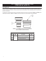
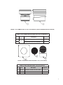
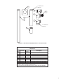
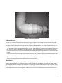
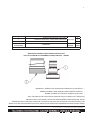
FIGURE 1. PVC COMMON VENT KIT (120 TO 250 MODELS)
(ONE KIT NEEDED FOR EACH HEATER)
TABLE 1. PVC COMMON VENT KIT PARTS LIST (120 TO 250 MODELS)
Item
No.
Kit
No.
Description
Kit
Supplied
1
100227396
VENT
ADAPTER,OUTLET,6”,PP,DURAVENT
1
2 VENT ADAPTER,PP/
PVC,STAINLESS,DURAVENT
1
3 INSTRUCTION,COMMON VENT KIT 1

5
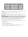
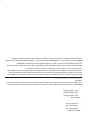
FIGURE 2. PVC COMMON VENT KIT (300 TO 500 MODELS) (ONE KIT NEEDED FOR EACH HEATER)
TABLE 2. PVC COMMON VENT KIT PARTS LIST (300 TO 500 MODELS)
Item
No.
Kit
No.
Description
Kit
Supplied
1
100223775
BACKFLOW PREVENTER, 300-500, DURAVENT 1
2 VENT ADAPTER, 300-500, SS, DURAVENT 1
1
2
3
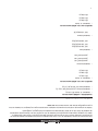
FIGURE 3. ADDITIONAL PARTS REQUIRED - PVC ( FOR US ONLY)
TABLE 3. FIELD SUPPLIED PARTS - PVC (FOR US ONLY)
Item
No.
Kit
No.
Description
Additional
Required
1 100110441 PLATE,WALL COVER,0.052”,GALV,STEEL 4
2 100226846 VENT SCREEN COUPLING ASSEMBLY,6” 1
3 100078784 AIR INTAKE TERMINAL 1

6
TABLE 4. FIELD SUPPLIED PARTS - ULC S636 PVC (FOR CANADA)
Kit
No.
Description
Additional
Required
100110441 PLATE,WALL COVER,0.052”,GALV,STEEL 4
IPEX 196142 (PVC) or
IPEX 197141 (CPVC)
COUPLING FOR VENT OUTLET 1
IPEX 196140 (PVC) or
IPEX 197203 (CPVC)
ELBOW FOR AIR INLET 1
100041999 SCREEN 2
SUPPORTS
You will need enough supports so that you can install one every 3 feet of horizontal run and every 5 feet of vertical run
for both the inlet and vent pipe. Supports may be eld supplied metal strapping or equivalent.
CONDENSATE DRAIN
Each water heater must have a separate condensate drain line running to an open drain. Follow the directions in the
water heater’s instruction manual. Do not use a common condensate drain line for multiple heaters.
INSTRUCTIONS
PHYSICAL LAYOUT - GENERAL
This kit may be used as part of a common vent installation of up to 3 120 models or up to 3 of any combination of
the models in the 150 to 250 group or the 300 to 500 group listed in Models Covered (page 2) in a direct vent
conguration. You may not mix water heaters from the different groups. Check local code requirements regarding
common venting of plastic pipe. In Canada, all plastic pipe must be listed to ULC S636.
NOTE: Do not use these parts to combine these water heaters with any other heater or gas appliance.
This kit is meant to common vent water heaters that are physically close to each other and facing the same direction.
Additional limits of this kit are:
• All heaters are on the same oor.
• Through the wall vent and air inlet terminations.
• All heaters are in the same room (pressure zone).
• No change to the system layout, as shown in Figure 4 (page 7), except as explained in these instructions.
• The adapters shown in Figure 1 (page 4) and Figure 2 (page 5) must not be modied.

7
The system layout must be planned to minimize the linear length and number of ttings in the system. The kit is
meant to accommodate heaters that maintain the recommended 24” clearance between the water heaters, (52” on
center for the 120 to 250 models and 57” on center for the 300 to 500 models). Consult the water heater’s installation
instructions for proper clearances for service. Consult the water heater’s instruction manual and see Figure 6 (page
9) for requirements for locating the air intake and vent terminals.
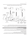
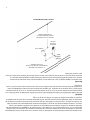
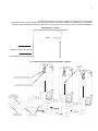
The common vent is the section of the vent and air inlet piping where the gases from all of the heaters ow together,
See Figure 4. The maximum equivalent length straight pipe and elbows of the common sections is 50 feet. The
minimum equivalent length of the common sections is 3 feet. Each 90° elbow is equal to 5 feet and a 45° elbow is
equal to 2½ feet. The maximum number of elbows is three. The air intake terminal (90° elbow) is not included in the
equivalent length.
MAXIMUM EQUIVALENT LENGTHS
The maximum equivalent lengths of the system are:
• Common section: 50 feet
• Connector height: 110”
• Heater spacing: 24” clearance (see above)
If it is necessary to modify the connectors or heater spacing, the equivalent length of additional vent connector, heater
spacing or elbows must be deducted from the 50 equivalent feet of the common vent or common air intake sections.
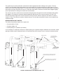
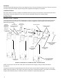
COMMON VENTING
AIR INTAKE TERMINAL
(FIELD SUPPLIED PARTS,
SEE TABLE 3 OR 4)
6"Ø VENT SCREEN
COUPLING ASSEMBLY
(FIELD SUPPLIED PAR
TS,
SEE TABLE 3 OR 4)
VENT ADAPTER PP/PVC, STAINLESS DURAVENT
(KIT SUPPLIED PARTS) (REFER TO TABLES 1 & 2)
VENT ADAPTER, OUTLET 6", PP, DURAVENT
(KIT SUPPLIED PARTS) (SEE TABLES 1 & 2)
INDIVIDUAL VENT
CONNECTOR
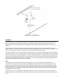
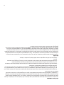
FIGURE 4. DEFINITION OF SYSTEM SECTIONS - PVC

8
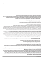
FIGURE 5. SANITARY TEE
Figure 4 shows the system constructed with straight tees. However, you can use also use sanitary tees, shown in
Figure 5, as an acceptable substitute, provided they are arranged so that the ows are in the directions indicated in
Figure 5.
The individual vent connectors attach the heaters to the common vent. The exhaust vent connectors are attached
to the water heater with the parts in the kit. The air inlet connectors are attached with PVC reducing ttings to the
heater’s PVC coupling. As shown in Figure 4, the individual vent connectors consist of vertical and horizontal sections
that connect the heater outlets to the common vent. Using different lengths of pipes, the height of the horizontal
sections may be adjusted to be from 80” to 110” from the bottom of the heater to the center-line of the horizontal
section. The combustion air and exhaust vent sides of the system may be different heights, but each must meet the
80” to 110” height requirement.
SUPPORT
DO NOT SUPPORT WEIGHT OF VENT SYSTEM ON THE HEATER. Supports must be installed every 3 feet of
horizontal run and 5 feet of vertical run for both the inlet and vent pipe. Supports may be made of eld supplied metal
strapping or equivalent. The common vent outlet piping must be sloped upwards toward the vent terminal at least 1/4”
per foot.
TERMINATIONS
See Figure 6 (page 9) for location requirements of horizontal vent and intake terminations. You must use the
terminations found in the additional required parts list. The air inlet terminal is a 90° elbow pointing down and the vent
outlet is the end of a straight pipe section, facing horizontally.
Vent Gas Direction
Combustion Air Direction

9
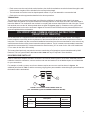
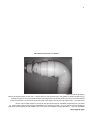
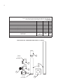
AIR INTAKE
A =
24” MINIMUM INCREASE
,
TO 40” INCHES IN COLD CLIMATES
6” MAX
VENT IN
LEFT
POSITION
12” ABOVE GRADE
OR MAXIMUM EXPECTED
SNOW LEVEL
FIGURE 6. WALL TERMINATIONS
ASSEMBLY
All joints that are PVC to PVC should be attached using approved solvent glue. See the water heater’s Instruction
Manual for additional details. Start the assembly at the wall termination and proceed towards the middle of the
common system. Next, start assembly at the appliances. This will allow small adjustments near the tees over the
heaters.
Wall Penetration - The general instructions for penetrating the side wall are found in the Side Wall Terminations
section of the water heater’s instruction manual. The common vent system may not be used with the concentric or low
prole vent terminals as described in the instruction manual supplied with the water heater.
For each penetration, cut a 7” diameter hole through the structure. First, attach the nal terminations for the exhaust
outlet and air intake to their nal, straight pipes. Outside the building, insert the last straight pipe sections through the
wall plates and then, through the penetration. Run a bead of eld-supplied silicone sealant around the wall plate and
press it in place. Inside the building, place a second wall plate over each of the pipes and seal the plates to the wall
with silicone sealant. After the vent system is completely set up, nish the penetrations by sealing the gap between
the pipe and wall plates with a bead of silicone sealant.
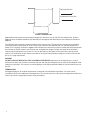
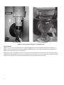
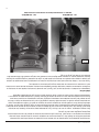
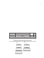
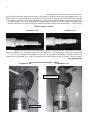
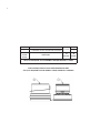
VENT
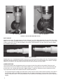
The exhaust vent is connected to the heater by two adapters. The vent outlet adapter/ backow preventer is
connected to the aluminum exhaust vent elbow by inserting the male end of the vent outlet adapter into the outlet
and securing it with the rubber boot and hose clamps (supplied with the water heater as shown in Figure 7). Next,
the Polypropylene/ PVC adapter is inserted into the outlet of the backow preventer and secured with the attached
locking ring. After that, the remainder of the exhaust vent side of the common system is composed of eld-supplied
Schedule-40 PVC pipe and ttings.
Straight pipe to tee - Use eld-supplied straight pipe sections to reach the horizontal part of the system that runs
above the heaters. The total height from the bottom of the heater to the center line of the horizontal must be from 80”
to 110”.

10
Locking Ring
120 - 250 MODELS 300 - 500 MODELS
FIGURE 7. OUTLET VENT ADAPTER TO PVC
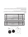
INLET AIR SIDE
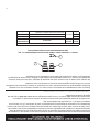
Attaching to the inlet - The water heater’s air inlet is either a 3” or 4” PVC tting (Figure 8). For the 120 to 250 models,
attach a 3” to 4” reducing adapter and then, a 4” to 6” reducing adapter to begin the 6” vent connector. The 300 to 500
models require only a 4” to 6” reducing adapter. A 90° elbow is then attached to turn the connector vertical, towards
the remainder of the system.
FIGURE 8. PVC AIR INLET
Straight pipe to tee - A straight pipe section is used to run from the elbow to the bottom of the tee. The length may be
adjusted so that the height to the center line of the horizontal run is 80” to 110” from the base of the heater. A straight
section is not required – you may insert the base of the tee into the female end of the elbow.
COMMON SECTIONS
The common sections are the pipes that carry the vent gas or intake air to and from the outside. Each pipe must
extend from the tee over the heaters to the outside/ outdoors etc. It is preferred to run the air and vent sections next
to each other, over a similar path as shown in Figure 4 (page 7). However, differences may be needed in the eld.
The requirements for both the air intake and vent common sections are:
• The equivalent length of straight pipe and elbows of each common section will be limited to between 3 feet and 50
feet. Each 90° elbow is equivalent to 5 feet pipe and a 45° elbow is equivalent to 2½ feet of pipe. The maximum
number of elbows is three. The terminal elbows are not considered in calculating maximum or minimum equivalent
lengths;
120 - 250 MODELS 300 - 500 MODELS
LOCKING
RING

11
• Each common section may include vertical sections, but the nal terminations must be horizontal through the wall.
Vertical section lengths must be included in the total equivalent length.
• The horizontal vent section must be sloped upward at least 1/4” per foot towards the vent terminal and
• Each section must be supported as detailed in the above procedure.
TERMINATIONS
The placement of the vent and air terminals must follow the guidelines for terminal location found in the water
heater’s Instruction Manual. All required clearances to building features are the same as found in the water heater’s
Instruction Manual. The combustion vent terminal is a coupling with a screen that nishes the end of the pipe. The air
inlet terminal must use the 90° elbow pointed down as shown in Figure 6 (page 9). Clearances to the ground and
to anticipated snow level must be as shown in Figure 6. The ends of both terminals must be protected with the bird
screens supplied with the terminations.
POLYPROPYLENE COMMON VENT KIT INSTRUCTIONS
(100227395 OR 100223774)
This kit instruction is a supplement to the Instruction Manual that is supplied with the water heater. The multiple
heater installation must satisfy all the requirements of the Instruction Manual as well as the requirements of this kit
instruction. The installer may also consult with installation instructions from the vent manufacturer. In the event of any
conict between the documents, these instructions take precedence. The kit is meant to accommodate heaters that
maintain the recommended 24” clearance between the water heaters, (52” on center for the 120 to 250 models and
57” on center for the 300 to 500 models).
The heaters listed previously may also be common vented using a Polypropylene system manufactured by M&G
Duravent. This is a system listed to UL 1738 and ULC S636 and may be required in some localities.
POLYPROPYLENE PARTS LIST
Each kit contains the adapters needed to connect the vent and air intake system to one heater. Additional parts are
needed to create the connectors, common sections and vent terminations. A list of additional parts is included below
for your convenience.
For example, to install a common vent for two heaters requires two common vent kits shown in Figure 9, the
additional parts listed in Table 7, and the necessary polypropylene parts needed to extend the pipe systems between
the heaters and the terminations.
2
1
3
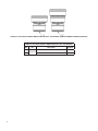
FIGURE 9. POLYPROPYLENE COMMON VENT KIT
(120 - 250 MODELS) (ONE KIT NEEDED FOR EACH HEATER)
TABLE 5. POLYPROPYLENE COMMON VENT KIT (120 - 250 MODELS)
Item
No.
Part
No.
Description
Kit
Supplied
1
100227395
VENT ADAPTER,OUTLET,6”,PP,DURAVENT 1
2 VENT ADAPTER,INLET,6”,PP,DURAVENT 1
3 VENT ADAPTER CONNECTOR,DURAVENT 1

12
FIGURE 10. POLYPROPYLENE COMMON VENT KIT (300 - 500 MODELS) (ONE KIT NEEDED FOR EACH HEATER)
TABLE 6. POLYPROPYLENE COMMON VENT KIT (300 -500 MODELS)
Item
No.
Part
No.
Description
Kit
Supplied
1
100223774
BACKFLOW PREVENTER, 300-500, DURAVENT 1
2 APPLIANCE-INCREASER, 300-500, DURAVENT 1

13
1
2
4
5
7
3
UV RESISTANT
(BLACK)
UV RESISTANT
(BLACK)
8
6
FIGURE 11. ADDITIONAL REQUIRED PARTS - POLYPROPYLENE
TABLE 7. ADDITIONAL REQUIRED PARTS - POLYPROPYLENE
PARTS LIST
Item
No.
Part No.
Duravent
Stock No.
Description
1
N/A 810009776
VENT PIPE,6”,72”,PP,DURAVENT
2 N/A 810009774 VENT PIPE,6”,36”,PP,UV,DURAVENT
3 N/A 810009772 VENT PIPE,6”,12”,PP,DURAVENT
4 N/A 810009787 VENT TEE W/CAP,90,6”,PP,DURAVENT
5 N/A 810009783 ELBOW,90,6”,PP,UV,DURAVENT
6 N/A 810004276 BIRD SCREEN,6”,DURAVENT
7 N/A 810009782 ELBOW,90,6”,PP,DURAVENT
8 100110441 N/A PLATE,WALL COVER,0.052”,GALV,STEEL
Notes:
1. ITEMS 1 THRU 7 ARE FIELD SUPPLIED ONLY
2. LOCKING RINGS ARE PREINSTALLED ON PIPES, TEES, AND ELBOWS

14
SUPPORTS
You will need enough supports so that you can install one every 3 feet of horizontal run and every 5 feet of vertical run
for both the inlet and vent pipe. Supports may be eld supplied metal strapping or equivalent.
CONDENSATE DRAIN
Each water heater must have a separate condensate drain line running to an open drain. Follow the directions in the
water heater’s Instruction Manual. Do not use a common condensate drain line for multiple heaters.
INSTRUCTIONS
PHYSICAL LAYOUT - GENERAL
The requirements for the layout of the Polypropylene common vent system, required lengths and terminal locations
are the same as for the PVC vent. The overall layout is shown in Figure 12. Consult the previous instructions for
additional requirements.
INDIVIDUAL VENT
CONNECTOR
6"Ø ELBOW
(FIELD SUPPLIED
PARTS)
INLET
VENT ADAPTER
(KIT SUPPLIED PARTS)
(SEE TABLES 4 & 5)
ADAPTER
CONNECTOR
(KIT SUPPLIED
PARTS, SEE
TABLES 4 & 5)
6 "Ø PIPE/ 12”
(FIELD SUPPLIED
PARTS)
6"Ø ELBOW UV RESISTANT
+
6"Ø BIRD SCREEN
(FIELD SUPPLIED
PARTS)
6"Ø BIRD SCREEN
(FIELD SUPPLIED
PARTS)
6"Ø PIPE
36" UV RESISTANT
(FIELD SUPPLIED
PARTS)
TERMINAL SECTIONS
(UV RESISTANT)
COMMON VENTING
OUTLET VENT ADAPTER
(KIT SUPPLIED PARTS)
(SEE TABLES 4 & 5)
FIGURE 12. DEFINITION OF SYSTEM SECTIONS - POLYPROPYLENE
NOTE: In both the air inlet and vent outlet sides, the female end of the pipe or tting is always towards the
terminations.
The general instructions for penetrating the side wall are found in the Side Wall Terminations sections of the water
heater’s Instruction Manual. The common vent system may not be used with concentric or low prole vent terminals.
All pipe and terminations that are outside the structure should be UV protected (black) parts.

15
SUPPORT
DO NOT SUPPORT WEIGHT OF VENT SYSTEM ON THE HEATER. Supports must be installed every 3 feet of
horizontal run and 5 feet of vertical run for both the inlet and vent pipe. Supports may be made of eld supplied metal
strapping or equivalent. The common vent outlet piping must be sloped upwards toward the vent terminal at least 1/4”
per foot.
TERMINATIONS
See Figure 6 (page 9) for location requirements of horizontal vent and intake terminations. You must use the
terminations found in the additional required parts list. The air inlet terminal is a 90° elbow pointing down and the vent
outlet is the end of a straight pipe section, facing horizontally.
ASSEMBLY
For each penetration, cut a 7” diameter hole through the structure. First, attach the nal termination for the air intake
to its nal straight pipe. Outside the building, insert the male end of the last straight pipe section through the wall plate
and then, through the penetration. This last section should be the UV protected pipe. Run a bead of eld-supplied
silicone sealant around the wall plate and press it in place. Inside the building, place a second wall plate over the
male end and seal the plate to the wall with silicone sealant. After the vent system is completely set up, nish the
penetration by sealing the gap between the pipe and wall plates with a bead of silicone sealant. Remove the rubber
gasket at the end of the inlet and outlet and insert the bird screen into the groove that is now available.
VENT
The vent adapter and back-ow preventer (Figure 13) is connected to the aluminum heater outlet and condensate
trap by inserting the male end of the vent outlet adapter into the outlet and securing it with the rubber boot and hose
clamps (supplied with the water heater).
Straight pipe to tee - Use eld-supplied straight vent sections to reach the horizontal part of the system that runs
above the heaters Note that the ow in a polypropylene vent pipe is always out of the female end. The total height
from the bottom of the heater to the center line of the horizontal must be from 80” to 110”.

16
LOCKING RING
120 - 250 MODELS 300 - 500 MODELS
FIGURE 13. OUTLET VENT ADAPTER TO POLYPROPYLENE
INLET AIR SIDE
Adapter to inlet - The male end of the air inlet adapter (Figure 14) is inserted into the water heater air inlet (a PVC
tting). It is held in place with the connector adapter supplied in this kit. A 90° elbow is inserted into the female end
adapter to turn the system in a vertical direction.
Straight pipe to tee - A straight pipe section is used to run from the elbow to the bottom of the tee. The length may be
adjusted so that the height to the center line of the horizontal run is 80” to 110” from the base of the heater. A straight
section is not required – you may insert the base of the tee into the female end of the elbow.

17
FIGURE 14. AIR INLET ADAPTER
COMMON SECTIONS
The common sections are the pipes that carry the vent gas or intake air from multiple units to and from the outside.
Each pipe must extend from the tee over the heaters to the outside/ outdoors etc. It is preferred to run the air and
vent sections next to each other, over a similar path as shown in Figure 12 (page 14). However, differences may be
needed in the eld. The requirements for both the air intake and vent common sections are:
• The equivalent length of straight pipe and elbows of each common section will be limited to between 3 feet and 50
feet. Each 90° elbow is equivalent to 5 feet pipe and a 45° elbow is equivalent to 2½ feet of pipe. The maximum
number of elbows is three. The terminal elbows are not considered in calculating maximum or minimum equivalent
lengths.
• Each common section may include vertical sections, but the nal terminations must be horizontal through the wall.
Vertical section lengths must be included in the total equivalent length.
• The horizontal vent section must be sloped upward at least 1/4” per foot towards the vent terminal.
• Each section must be supported as detailed in the above procedure.
TERMINATIONS
The placement of the vent and air terminals must follow the guidelines for terminal location found in the water
heater’s Instruction Manual. All required clearances to building features are the same as found in the water heater’s
Instruction Manual. The combustion vent terminal is a coupling with a screen that nishes the end of the pipe. The air
inlet terminal must use the 90° elbow pointed down as shown in Figure 6 (page 9). Clearances to the ground and
to anticipated snow level must be as shown in Figure 6. The ends of both terminals must be protected with the bird
screens supplied with the terminations.

18
NOTES

19
NOTES

20
For additional information contact:
1-800-527-1953
www.hotwater.com
La page charge ...
La page charge ...
La page charge ...
La page charge ...
La page charge ...
La page charge ...
La page charge ...
La page charge ...
La page charge ...
La page charge ...
La page charge ...
La page charge ...
La page charge ...
La page charge ...
La page charge ...
La page charge ...
La page charge ...
La page charge ...
La page charge ...
La page charge ...
-
 1
1
-
 2
2
-
 3
3
-
 4
4
-
 5
5
-
 6
6
-
 7
7
-
 8
8
-
 9
9
-
 10
10
-
 11
11
-
 12
12
-
 13
13
-
 14
14
-
 15
15
-
 16
16
-
 17
17
-
 18
18
-
 19
19
-
 20
20
-
 21
21
-
 22
22
-
 23
23
-
 24
24
-
 25
25
-
 26
26
-
 27
27
-
 28
28
-
 29
29
-
 30
30
-
 31
31
-
 32
32
-
 33
33
-
 34
34
-
 35
35
-
 36
36
-
 37
37
-
 38
38
-
 39
39
-
 40
40


State 100280793 Manuel utilisateur
- Taper
- Manuel utilisateur
- Ce manuel convient également à
dans d''autres langues
- English: State 100280793 User manual
Autres documents
-
Rinnai RUR98EN Guide d'installation
-
Rheem ECOH180XELP-1 Manuel utilisateur
-
NAPOLEON WSX060T3AA-N Le manuel du propriétaire
-
Rinnai Circ-Logic RU80e Mode d'emploi
-
-
-
-
Hayward H150FDP Le manuel du propriétaire
-
Rinnai RUS65EP Manuel utilisateur
-
Rinnai REU-KCM2025W-US-N Guide d'installation