Detail K2 Folding Trailer Kit Le manuel du propriétaire
- Taper
- Le manuel du propriétaire

MFT4X8 man v.200615
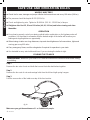
STOP!
Questions, problems, missing parts? Do not return to your retailer.
Please call our customer service department at: 1(888) 277-6960. Our customer service staff are ready to provide assistance.
If a part is damaged or missing, replacement parts can be shipped from our facility. For immediate help with assembly, or for
additional product information, call our North American toll-free number: 1(888) 277-6960.
Save this manual
You will need this manual for safety instructions, operating procedures, and warranty.
Put it and the original sales invoice in a safe, dry place for future reference.
ARRÊTEZ!
Vous avez des questions, des problèmes, ou des pièces manquent? Ne retournez pas chez votre détaillant.
Veuillez appeler notre service à la clientèle au: 1-888-277-6960. Notre personnel du service à la clientèle est prêt à
vous fournir une assistance.
Si une pièce est endommagée ou manquante, une pièce de remplacement peut vous être expédiée rapidement de nos
installations. Pour une aide immédiate à l’assemblage ou pour plus d’informations sur le produit, veuillez communiquer avec
notre numéro sans frais 1-888-277-6960.
Conservez ce manuel
Ce manuel vous offre des instructions sur la sécurité, des procédures opérationnelles et votre garantie.
Gardez-le ainsi que votre facture originale dans un endroit sec et sécurisé pour référence future.
DETAIL K2 INC.
1080 Clay Ave., Unit #2
Burlington Ont. L7L 0A1
1-888-277-6960
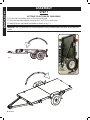
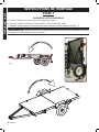
4 ft. x 8 ft. Folding Trailer
4 ft. x 8 ft. Folding Trailer
Owner’s Manual
Owner’s Manual
Model MFT4X8
Model MFT4X8
8 ft. (244 cm)
Utility
Trailer

2 MFT4X8 man
ENGLISHENGLISH
WARNING! Please read through these instructions completely BEFORE you begin to assemble
and install your DK2 trailer. Failure to follow the instructions closely could cause serious personal
injury or property damage.
Thank for very much for choosing a DK2 product! For further reference, please complete the owner’s
records below:
Model: _______________ Purchase Date: _______________
Save the receipt, warranty and these instructions. It is important that you read the entire
manual to become familiar with this product before you begin using it.
This trailer is designed for certain applications only. The distributor cannot be responsible for issues
arising from modication. We strongly recommend this trailer not be modied and/or used for any
application other than that for which it was designed. If you have any questions relative to a particular
application, DO NOT use the trailer until you have rst contacted the distributor to determine if it can
or should be performed on it.
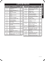
TABLE OF CONTENTS
TABLE OF CONTENTS
Important safe operating practices ...........................................................................................................3
General warnings .....................................................................................................................................4
Specic operation warnings......................................................................................................................4
Contents ...................................................................................................................................................5
Technical specications ............................................................................................................................5
General warnings .....................................................................................................................................5
Bed assembly ...........................................................................................................................................7
Drawbar assembly ................................................................................................................................... 8
Spring hanger assembly ........................................................................................................................... 9
Fender kit assembly .................................................................................................................................10
Spring and axle assembly .......................................................................................................................11
Tire assembly ...........................................................................................................................................12
Getting your trailer tow ready ...................................................................................................................14
Lighting kit installation .............................................................................................................................15
Wiring the trailer ......................................................................................................................................16
Attaching the coupler ................................................................................................................................ 19
Safe use and operation rules....................................................................................................................21
Towing vehicle ..........................................................................................................................................21
Hitch, ball, coupler ....................................................................................................................................21
Safety chains ............................................................................................................................................21
Loading ..................................................................................................................................................... 21
Lighting .....................................................................................................................................................21
Wheels and tires ....................................................................................................................................... 22
Operation .................................................................................................................................................. 22
Folding the trailer ...................................................................................................................................... 22
Maintenance .............................................................................................................................................23
Canadian trailer licensing notice ..............................................................................................................24
U.S.A trailer licensing notice ....................................................................................................................24
Licensing ..................................................................................................................................................24
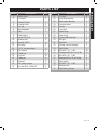
Parts List...................................................................................................................................................25
Schematic diagram ................................................................................................................................... 26

v.200615 3
ENGLISHENGLISH
IMPORTANT SAFE OPERATING PRACTICES
IMPORTANT SAFE OPERATING PRACTICES
IMPORTANT: Read safety rules and instructions carefully before using this equipment.
Read and follow instructions carefully. Save owner’s manual for future reference or parts
information. Be certain any future user of this carrier is aware of correct attachment and use.
CAUTION: Safety First — Read this manual carefully before attaching and using your trailer.
We recommend that you read this manual completely so that you are fully aware of all important
safety recommendations. Record your serial number.
DANGER: This equipment was built to be operated according to the rules for safe operation
in this manual. As with any type of equipment, carelessness or error on the part of the operator can
result in serious injury or property damage.
zTo use this equipment properly, you must observe the safety regulations, the assembly instructions
and the operating instructions to be found in this manual.
zAll persons who use and service the trailer must be informed about potential hazards and must be
well acquainted with this manual.
IMPORTANT WARNING: It is critical that your DK2 Trailer is properly secured to the
vehicle.
zAttaching it improperly could result in a vehicular accident, causing serious bodily harm, injuries,
or death to you or to others.
zSecuring trailers and accessories to your vehicle is your legal responsibility. Check the trailer prior
to use, and inspect the components for adjustment, wear, and damage periodically.
zYou must read and understand all of the instructions and cautions before you install or use the
trailer.
zIf you do not understand all of the instructions and cautions, or if your mechanical experience
precludes following them, have the trailer installed by a professional.
WARNING: You are responsible to ensure the trailer attaches safely and securely to the
vehicle.
zThis trailer is designed for use on passenger cars, trucks, and SUVs that have the trailer hitch
and weight capacity.
zInappropriate use and fastening of the trailer to the vehicle may lead to damage to cargo, the
trailer, and/or your vehicle. It may also inict damage on other vehicles behind and elsewhere on
the road with you.
zDo not take the trailer through an automatic car wash.

4 MFT4X8 man
ENGLISHENGLISH
GENERAL WARNINGS
GENERAL WARNINGS
WARNING: Read and understand all instructions. Failure to follow all instructions listed
below may result in electric shock, re and/or serious injury.
WARNING: The warnings, cautions, and instructions discussed in this instruction manual
cannot cover all possible conditions or situations that could occur. It must be understood by the
operator that common sense and caution are factors that cannot be built into this product, but must
be supplied by the operator.
1. KEEP THE WORK AREA CLEAN AND DRY. Damp or wet work areas can result in injury.
2. KEEP CHILDREN AWAY FROM WORK AREA. Do not allow children to handle this product.
3. ALWAYS WEAR ANSI-APPROVED SAFETY GLASSES AND HEAVY-DUTY WORK GLOVES during
assembly and use. Do not wear loose clothing or jewelry which can get caught in moving parts.
4. READ YOUR OWNER’S MANUAL CAREFULLY. Get to know your trailer and familiarize yourself with its
applications and limitations.
5. USE THE TRAILER ACCORDING TO THE GUIDELINES IN THIS MANUAL. Do not abuse it or force it to
do a job for which it was not designed.
6. USE ONLY ORIGINAL EQUIPMENT PARTS AND ACCESSORIES. Consult this owner’s manual. The use
of incorrect accessories may produce unforeseen hazards.
7. STORE IDLE EQUIPMENT. When not in use, tools and equipment should be stored in a dry location to
inhibit rust. Always lock up tools and equipment, and keep out of reach of children.
8. USE THE RIGHT TOOL FOR THE JOB. Do not attempt to force small equipment to do the work of
larger industrial equipment. There are certain applications for which this equipment was designed.
It will do the job better and more safely at the capacity for which it was intended. Do not modify this
equipment, and do not use this equipment for a purpose for which it was not intended.
9. CHECK FOR DAMAGED PARTS. Before using this product, carefully check that it will operate properly
and perform its intended function. Check for damaged parts and any other conditions that may
affect the operation of this product. Replace damaged or worn parts immediately.
10. DO NOT OVERREACH. Keep proper footing and balance at all times to prevent tripping falling, back
injury, etc.
11. DO NOT USE THIS TRAILER WHEN TIRED OR DISTRACTED.
12. INDUSTRIAL APPLICATIONS MUST FOLLOW OSHA REQUIREMENTS.
SPECIFIC OPERATION WARNINGS
SPECIFIC OPERATION WARNINGS
1. BEFORE EACH USE, ALWAYS EXAMINE THE TRAILER for proper tire (13) condition and air pressure,
damaged Tail Lights (30L, 30R), damaged Side Running Lights (38), loose bolts and nuts,
structural cracks, bends and any other condition that may affect its safe operation. Do not use the
Trailer even if minor damage appears.
2. BEFORE EACH USE, ALWAYS ATTACH THE SAFETY CHAINS (1) of the trailer to the towing vehicle.
Make sure the Safety Chains are attached to the towing vehicle with an equal length at each side.
Do not allow the Safety Chains to drag on the ground.
3. ALWAYS CHECK TO MAKE SURE THE PAYLOAD BEING TRANSPORTED IS PROPERLY AND SAFELY
SECURED IN THE TRAILER. Load the trailer evenly from side to side with 60% of the load weight
forward of the Axle (7).
4. MAKE SURE THE TOWING VEHICLE IS CAPABLE OF TOWING THIS TRAILER AND ITS PAYLOAD. Make
sure the hitch on the towing vehicle is capable of towing the trailer and its payload. The towing

v.200615 5
ENGLISHENGLISH
capacity of the hitch is typically stamped on the hitch drawbar.
5. MAKE SURE the hitch coupler (7) and the vehicle’s Ball Hitch (not included) are of equal mating size
(2”) and are rated equal to or greater than the weight of the trailer and its payload.
6. DO NOT EXCEED 45 MILES PER HOUR (72 km/h) when towing the trailer. Excess speed is a major
cause of vehicle-trailer accidents.
7. DO NOT ATTEMPT TO POWER THE TRAILER LIGHTS WITH ANY OTHER THAN THE CORRECT TYPE OR
VOLTAGE ELECTRICAL CURRENT. The LED tail lights supplied with this trailer are for a 12 volt DC
electrical system only.
8. PARK THE TRAILERS ON A FLAT, LEVEL, PAVED SURFACE AND CHOCK BOTH TIRES whenever
possible, to keep the trailer from accidently moving.
9. BEFORE ATTEMPTING TO FOLD UP THE TRAILER, make sure it is on a at, level, solid surface and
chock both Tires (13).
10. NEVER ATTEMPT TO FOLD UP THE TRAILER WITHOUT THE HELP of one or two able assistants.
11. DO NOT EXCEED THE 1450 POUND WEIGHT CAPACITY.
12. DO NOT ALLOW ANYONE TO RIDE in a towed vehicle or on the trailer.
13. DO NOT TRANSPORT PASSENGERS OR HEAVY CARGO INSIDE A VEHICLE that is being towed.
14. THE COUPLER MUST BE PROPERLY SECURED TO THE HITCH BALL. After assembly and attachment,
pull up and down on the hitch coupler to make sure the hitch ball is snug in the hitch coupler. If the
coupler is not secured properly, it could come loose while the trailer is in motion, causing property
damage, serious personal injury or even death.
15. MAKE WIDE TURNS when towing a loaded trailer, avoiding both sharp turns and U-turns. Turning
too sharply can cause damage to the trailer and/or the tow vehicle.
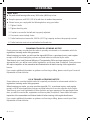
UNPACKING
UNPACKING
zWhen unpacking, check to make sure all the parts shown on the Parts List (see p. ) are included.
zIf any parts are missing or broken, please contact with us.
TECHNICAL SPECIFICATIONS
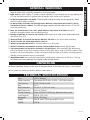
TECHNICAL SPECIFICATIONS
Tires 5.30-12 tubeless
Wheel Lug Nuts 5 per wheel: 85-90 ft-lb. (115.24 - 122.02 Nm) torque
Tire Pressure 80 PSI (552 kPa) cold
Rim 12 x 5
Bed Dimensions 4 ft. x 8 ft. (1.22 m x 2.44 m)
Ball/Coupler size 2 Inch (≈ 50 mm)
Coupler capacity Class II; 3500 lb. (1587.6 kg), Maximum Gross Load
Load Capacity 1450 lb. (657.7 kg)
Net weight 262 lb. (118.8 kg)
GAWR 1980 lb. with 5.30-12 tires at 80 PSI cold
GVWR 1720 lb.
GENERAL WARNINGS
GENERAL WARNINGS

6 MFT4X8 man6 MFT4X8 man
ENGLISHENGLISH
ASSEMBLYASSEMBLY
Read the following instructions step by step. Refer also to the complete parts and hardware list.
Average assembly time is 1 hour.
You will need the following tools to assemble your trailer:
NOTE:
zThe trailer parts are called out by standing at the rear of the trailer looking toward the hitch. The
trailer frame parts are labeled.
zDo not tighten any nuts and bolts until the entire trailer is assembled.
zPeriodically check all the nuts and bolts for tightness.
zTighten the wheel lug nuts to 85-90 ft-lb. (115.24 - 122.02 Nm) of torque after assembling the
trailer, after the rst 20, 50 and 100 miles (30, 80, and 160 kilometres) of driving and before each
tow thereafter.
16 mm wrench or socket
17 mm wrench or socket
18 mm wrench or socket
19 mm wrench or socket
20 mm wrench or socket
21 mm wrench or socket
Pliers
Phillips screwdriver
Rubber mallet

v.200615 7
ENGLISHENGLISH
ASSEMBLYASSEMBLY
STEP 1
STEP 1
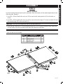
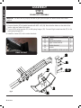
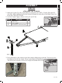
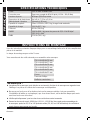
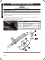
BED ASSEMBLY
Lay the front bed (26) and rear bed (21) as shown. Note the location of the marker lights holes in the
front side rails. See g.1
1. Use M10 x 20 hex head bolts and nuts (34) to mount the 8 stake pockets (40) to the trailer as
shown.
2. Use M10 x 20 hex head bolts and nuts (34) to mount the inside hinge (27) to the front bed (26) and
the outside hinge (28) to the rear bed (31);
NOTE: Do not join the hinges from front to rear bed halves yet.
3. Keep the two center M10 x 20 hex head bolts and nuts (34) to connect the bed halves aside until
you are ready to join the bed halves and make the trailer one solid deck.
NOTE: Do not join the bed halves until later in the assembly process, set the rear bed half
aside for later in the assembly.
Item No. Description Qty.
34 Hex M10 x 20 & nut (set) 28
40 Stake pocket 8
28 Outside hinge 2
27 Inside hinge 2
34
40
40
40
34
28
27
40
27
28
34
34
34
�ig.1

8 MFT4X8 man8 MFT4X8 man
ENGLISHENGLISH
ASSEMBLYASSEMBLY
STEP 2
STEP 2
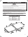
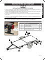
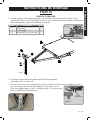
DRAWBAR ASSEMBLY
1. Flip the front bed half over so it is upside down.
2. Position drawbar (5L, 5R) to the trailer front bed (26), tting the bars into the U slots on the front
cross member.
3. Use L latch (37) to go through the U bracket and lock with R clip after then.
4. Use M10 x 30 (36), M12 x 25 (39) to connect the drawbar end to trailer side rails. Do not tighten the
bolts until all bolts in position.
5. Connecting drawbar T plate (3), drawbar coupler base (4) as shown with M10 x 20 (34)
Item No. Description Qty.
3Tow bar T-plate 1
4 Coupler base 1
5 Tow bar 2
34 Hex M10 x 20 bolt & nut (set) 12
Item No. Description Qty.
36 Hex bolt M10 x 30 & nut (set) 2
37 Hitch pin Ø12 x 75 & R clip
(set) 2
39 Hex bolt M12 x 25 & nut (set) 2
�ig.2

v.200615 9
ENGLISHENGLISH
ASSEMBLYASSEMBLY
STEP 3
STEP 3
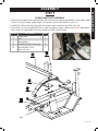
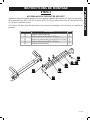
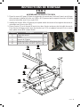
SPRING HANGER ASSEMBLY
Install the Left spring hanger (19) and Right spring hanger (shown, 41, g.3) to trailer sides with M10
x 20 (34) at front, M10 x 30 (36) in the middle and M10 x 25 carriage bolts (35) for rear end.
(35) insert nger tight for later in the assembly process, this will secure your bed halves
Item No. Description Qty.
19 Left spring hanger 1
34 Hex bolt M10 x 20 & nut (set) 4
35 Carriage bolt M10 x 25 & nut (set) 4
36 Hex M10 x 30 bolt & nut (set) 2
41 Right spring hanger 1
�ig.3

10 MFT4X8 man10 MFT4X8 man
ENGLISHENGLISH
ASSEMBLYASSEMBLY
STEP 4
STEP 4
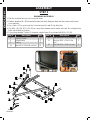
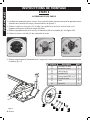
FENDER KIT ASSEMBLY
NOTE: You will have to prop up the bed to give yourself space to attach fender and caster
bracket.
1. Connect the fender bracket (24) to spring hangers (19,41) with M10 x 20 bolts and nuts (34).
2. Connect fender (25) to fender bracket with M10 x 20 (34). Note that the holes on the side of the
fender edge are toward the trailer.
3. Connect left caster bracket (22) to left spring hanger (19). Connect Right caster bracket (23) to the
right spring hanger(41).
4. Install the caster (21) to the caster brackets.
Item No. Description Qty.
21 Caster 4
22 Left caster bracket 1
23 Right caster bracket 1
24 Fender bracket 2
25 Fender 2
34 Hex bolt M10 x 20 & nut (set) 12
�ig.4
FINAL RESULT

v.200615 11
ENGLISHENGLISH
ASSEMBLYASSEMBLY
STEP 5
STEP 5
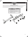
SPRING AND AXLE ASSEMBLY
1. Place 3 leaf spring (8) into spring hanger with eye forward, towards the drawbar of the trailer. Install
M14 x 85 (9) go through spring hanger, and spring eye and lock with M14 nyloc nut.
2. Install M14 x 85 go through spring tail and spring hangers and lock with M14 nyloc nut.
3. Place Axle (7) onto spring (8) with hole in axle over peg on spring. Fasten Axle to each spring with
two U bolts (9), spring plate (6) and lock with four M10 nuts as shown.
Item No. Description Qty.
6 Spring plate 2
7 Axle 1
8 3-leaf spring 2
9 U-bolt M10 x 85 & nuts (set) 4
20 Hex bolt M14 x 85 &
nyloc nut (set) 4
�ig.5

12 MFT4X8 man12 MFT4X8 man
ENGLISHENGLISH
ASSEMBLYASSEMBLY
STEP 6
STEP 6
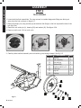
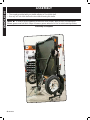
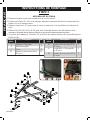
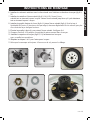
TIRE ASSEMBLY
1. Locate both tire/hub assemblies. For easy access, be certain thatgrease ttings are facing out
away from the hub as shown in gure 6-1.
2. Remove hubcap (21) using a small pry bar between the ange on the hub cap and the face of the
hub (g.6-2a).
3. Remove 4 mm cotter pin (L), bearing (20) and washer (N). See gure 6-2b.
4. Remove castle nuts (H) from axle ends.
5. Carefully slide tire/hub assembly onto axle with lug nuts facing outward. See g. 6-3
Item No. Description Qty.
11 Bearing 2
12 Hub assembly 2
13 Tire and rim 2
14 Washer M22 2
15 Castle nut M22 x 1.5 2
16 Cotter pin 2
17 Lug nut 10
18 Dustcap 2 .
�ig.6-1
21
�ig.6-2a
�ig.6-2b
�ig.6-3

v.200615 13
ENGLISHENGLISH
ASSEMBLYASSEMBLY
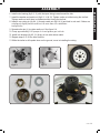
6. Install outer bearing (g.6-3, 11) with the taper facing inward toward the hub.
7. Install the washer and castle nut (g.6-3, 14 & 15). Tighten castle nut while turning the tire/hub.
Tighten castle nut until there is resistance while turning the tire/hub.
8. Install 4 mm cotter pin (g.6-4, L) through castle nut (g.6-4, H) and hole in axle end. If holes are
not aligned, slightly loosen castle nut -no more than one castellation-
to align holes.
9. Spread cotter pin (L) to retain castle nut. See gure 6-4.
10. Pump approximately 8-10 pumps of a hand grease gun into hub.
11. Install hub dustcap (g.6-5, 21) rmly on hub with rubber mallet.
12. Repeat steps 2-11 for the other tire/hub.
13. While the trailer is still upside down on the ground, move to installing the wiring.
�ig.6-4
�ig.6-5

14 MFT4X8 man14 MFT4X8 man
ENGLISHENGLISH
ASSEMBLYASSEMBLY
STEP 7
STEP 7
GETTING YOUR TRAILER TOW READY
1. Lay the rear bed upside down on the front trailer bed
2. Fasten the brackets together using the M10 x 20 (34) on both sides
3. Carefully ip the rear trailer bed down as shown in g. 7-1
NOTE: two (35) and two (34) can be inserted to join your bed halves and have your trailer tow
ready.
�ig.7-1
�ig.6

v.200615 15
ENGLISHENGLISH
ASSEMBLYASSEMBLY
STEP 8
STEP 8
LIGHTING KIT INSTALLATION
1. Attach the Light Brackets (33) to the Rear Left Side Rail and Rear Right Side Rail by using four
sets of M10 x 20 Bolts and M10 Nuts (44).
2. Attach the License Plate Bracket (29) with the Left Tail Light (30L) to the Light Bracket on the Rear
Left Side Rail, using M10 Nuts.
3. Attach the Right Tail Light (30R) to the Light Bracket on the Rear Right Side Rail, using M10 Nuts.
4. Attach the Side Running Light to the Front Left Side Rail, using 4 mm Self-Tapping Screws from the
light package.
NOTE: The trailer should be, at this point, upside down. Fig.7 shows the position of the lighting
components on a right-side up trailer for clarity.
�ig.7
Item No.Description Qty.
29 Licence holder 1
30 Rear light 2
33 Light bracket 2
34 Hex bolt M10 x 20 & nut
(set) 4
38 Side marker 2

16 MFT4X8 man16 MFT4X8 man
ENGLISHENGLISH
ASSEMBLYASSEMBLY
STEP 9
STEP 9
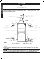
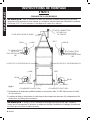
WIRING THE TRAILER
NOTE: Only a qualied technician should perform the electrical service that may be needed to
enable your particular make/model vehicle to power the Trailer’s 12 volt DC lighting system. This is
beyond the scope of this manual.
�ig.8-1
WHITE GROUND WIRE
BROWN
BROWN
BROWN BROWN
BROWN
BROWN
YELLOW
YELLOW
YELLOW
LEFT TAIL LIGHT (30L)
RIGHT TAIL LIGHT (30R)
GREEN
GREEN
GREEN
WIRE HARNESS
CONNECTOR PLUG
LEAVE EXCESS WIRE HERE
LEAVE EXCESS WIRE HERE
WIRE LEAD
FROM
SIDE RUNNING LIGHT
(38)
WIRE LEAD
FROM
SIDE RUNNING LIGHT
(38)
1. Have a qualied service technician install a 4-wire, 12 VDC connector in the trunk area of your
vehicle.
2. Locate the vehicle’s connector plug near the Trailer’s Coupler (2) and lay out the Trailer’s wiring
harness wires.
NOTE: g.8-1 and 8-2 show the trailer right side up. Keep in mind, the trailer is actually upside
down at this point to make wiring installation easier, so the left and right sides appear reversed.

v.200615 17
ENGLISHENGLISH
ASSEMBLYASSEMBLY
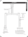
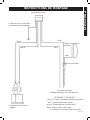
�ig.8-2
White ground wire
to trailer tongue
4-pin connector
Brown Brown
Yellow Green
Brown
Brown
Yellow
Left light (Yellow lead)
Right light (Green lead)
Side marker lights
Black
Wire clip
Brown tail lamp wires
Wired same as left side
KEY / COLOR CODES
Brown: Tail and side marker lights
Green: Right directional and stop light
Yellow: Left directional and stop light
White: Ground to trailer frame
O Indicates wire nut connection

18 MFT4X8 man18 MFT4X8 man
ENGLISHENGLISH
ASSEMBLYASSEMBLY
3. Connect the brown wire to the vehicle’s left tail light by stripping, wrapping, and taping the
connector plug.
4. Connect the yellow wire to the vehicle’s left signal and stop light wire.
5. Connect the green wire to the vehicle’s right signal and stop light wire.
6. Attach the white ground wire at the plug end of the wiring harness to the small mounting hole in the
Tow Bar (5) with a 1/4” (6 mm) tapping screw (not included).
See J, g.8-3.
7. Run the yellow/brown wires along the inside of the Front Cross Member (39) to the Side Running
Light (38) on the Front Left Side Rail (26).
8. Run the green/brown wires along the inside of the Front Right Side Rail to the other Side Running
Light.
9. Connect the wire lead from the two Side Running Lights to the brown wire on each side of the
trailer, using wire connectors. Then insert wire clips along the entire length of the side rails of the
Trailer to hold down the wiring harness.
10. Run the yellow/brown wires to the Left Tail Light (30L), leaving some excess wire where the frame
folds.
11. Strip approximately 3/4” (19 mm) of insulation off the ends of the wires.
12. Connect the yellow wire to the yellow wire of the Left Tail Light.
13. Connect the brown wire to the brown wire of the Left Tail Light.
14. Run the green/brown wires to the Right Tail Light (30R), leaving some excess wire where the
frame folds.
15. Strip approximately 3/4” (19 mm) of insulation off the ends of the wires.
16. Connect the green wire to the green wire of the Right Tail Light.
17. Connect the brown wire to the brown wire of the Right Tail Light.
NOTE: Use dielectric grease on each connector for corrosion prevention
18. Turn over the whole trailer assembly so the tires touch the ground.
CAUTION! Make sure you get the assistance of 1 or 2 additional people. Do not try this on
your own.
19. Even though the wheels were already mounted to the hubs, you must tighten all the lug nuts (I) to
85-90 lb/ft of torque.
�ig.8-3

v.200615 19
ENGLISHENGLISH
ASSEMBLYASSEMBLY
STEP 10
STEP 10
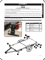
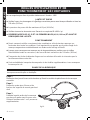
ATTACHING THE COUPLER
1. Attach the Coupler (2) to the Coupler Base (4), using two sets of M12 x 75 bolts (20b) and M12
nuts (20n). When installing the front bolt, thread it through the center link of the Safety Chain (1) to
secure the Chain to the Coupler.
2. Lock the Coupler Trigger, using its Locking Pin and R-Clip.
3. Pull up and down on the coupler to see if the coupler is tting snug on the ball. There must not be
play between the ball and coupler. If there is play, tighten the adjustment
nut until no play is present. If the nut is too tight, the handle will not lock.
�ig.9-1
b
n
fig.9-2 Safety Pin
R Clip Latch Trigger
�ig.9-3
Adjustment Nut
Item No. Description Qty.
1 Safety chain 1
2 2 inch coupler 1
20 Hex bolt M12 x 80 & nut (set) 2

20 MFT4X8 man20 MFT4X8 man
ENGLISHENGLISH
ASSEMBLYASSEMBLY
WARNING! Risk of trailer uncoupling.
• The coupler provided with your trailer requires a 2 inch hitch ball.
• Use only a 2 inch hitch ball on the tow vehicle towing this trailer
NOTE: To reduce friction between the ball hitch and coupler, apply a layer of multipurpose
lithium grease over ball hitch. Wipe off excess grease when not in use to avoid staining clothes.
Assembly is complete
La page est en cours de chargement...
La page est en cours de chargement...
La page est en cours de chargement...
La page est en cours de chargement...
La page est en cours de chargement...
La page est en cours de chargement...
La page est en cours de chargement...
La page est en cours de chargement...
La page est en cours de chargement...
La page est en cours de chargement...
La page est en cours de chargement...
La page est en cours de chargement...
La page est en cours de chargement...
La page est en cours de chargement...
La page est en cours de chargement...
La page est en cours de chargement...
La page est en cours de chargement...
La page est en cours de chargement...
La page est en cours de chargement...
La page est en cours de chargement...
La page est en cours de chargement...
La page est en cours de chargement...
La page est en cours de chargement...
La page est en cours de chargement...
La page est en cours de chargement...
La page est en cours de chargement...
La page est en cours de chargement...
La page est en cours de chargement...
La page est en cours de chargement...
La page est en cours de chargement...
La page est en cours de chargement...
La page est en cours de chargement...
La page est en cours de chargement...
La page est en cours de chargement...
-
 1
1
-
 2
2
-
 3
3
-
 4
4
-
 5
5
-
 6
6
-
 7
7
-
 8
8
-
 9
9
-
 10
10
-
 11
11
-
 12
12
-
 13
13
-
 14
14
-
 15
15
-
 16
16
-
 17
17
-
 18
18
-
 19
19
-
 20
20
-
 21
21
-
 22
22
-
 23
23
-
 24
24
-
 25
25
-
 26
26
-
 27
27
-
 28
28
-
 29
29
-
 30
30
-
 31
31
-
 32
32
-
 33
33
-
 34
34
-
 35
35
-
 36
36
-
 37
37
-
 38
38
-
 39
39
-
 40
40
-
 41
41
-
 42
42
-
 43
43
-
 44
44
-
 45
45
-
 46
46
-
 47
47
-
 48
48
-
 49
49
-
 50
50
-
 51
51
-
 52
52
-
 53
53
-
 54
54


Detail K2 Folding Trailer Kit Le manuel du propriétaire
- Taper
- Le manuel du propriétaire
dans d''autres langues
Documents connexes
Autres documents
-
Powerfist 8157323 Le manuel du propriétaire
-
-
-
-
-
-
-
DK2 MMT5X7 Guide d'installation
-
-
Generac MLT3080 Manuel utilisateur