
1
Smart Video Intercom S
INSTALLATION MANUAL
Model CAPXS

2
To reduce the risk of SEVERE INJURY or DEATH:
• Disconnect power at the fuse box BEFORE proceeding.
• To AVOID damaging gas, power or other underground utility
lines, contact underground utility locating companies BEFORE
digging.
• ALL electrical connections MUST be made by a qualified
individual.
• ALL power and control wiring MUST be run in separate
conduit.
• All power wiring should be on a dedicated circuit and well
protected. The location of the power disconnect should be
visible and clearly labeled.
• The CAPXS shall be installed in accordance with the National
Electrical Code and all local codes.
To protect against fire and electrocution:
• Disconnect power BEFORE installing or servicing CAPXS.
• NEVER connect a keypad/reader or lock to doors without first
consulting the applicable fire code.
• You MUST consult with, and get approval from, local fire
officials BEFORE installing locks or devices on ANY doors that
may be fire exits.
• Use of egress push buttons may not be legal. Single action
exits may be required.
• ALWAYS obtain proper permits and approvals in writing
BEFORE installing equipment.
DO NOT INSTALL THE SYSTEM IN THE FAIL SECURE MODE
UNLESS PERMITTED BY THE LOCAL AUTHORITY HAVING
JURISDICTION. Doing so may cause interference with the
operation of panic hardware.
Safety
Safety Symbol and Signal Word Review
When you see these Safety Symbols and Signal Words on
the following pages, they will alert you to the possibility of
serious injury or death if you do not comply with the warnings
that accompany them. The hazard may come from something
mechanical or from electric shock. Read the warnings carefully.
When you see this Signal Word on the following pages, it will alert
you to the possibility of damage to your property or product if you
do not comply with the cautionary statements that accompany it.
Read them carefully.
MECHANICAL
ELECTRICAL
WARNING: This product can expose you to chemicals
including lead, which are known to the State of California to
cause cancer or birth defects or other reproductive harm.
For more information go to www.P65Warnings.ca.gov.

3
ACCOUNT SETUP NETWORK/MOUNTINGPOWER ACCESS CONTROLINTRODUCTION
INTRODUCTION ACCOUNT SETUP NETWORK/MOUNTINGPOWER ACCESS CONTROL
INTRODUCTION ACCOUNT SETUP NETWORK/MOUNTINGPOWER ACCESS CONTROL
INTRODUCTION ACCOUNT SETUP NETWORK/MOUNTINGPOWER ACCESS CONTROL
INTRODUCTION ACCOUNT SETUP NETWORK/MOUNTINGPOWER ACCESS CONTROL
INTRODUCTION
CAPXS Overview ........................................................... 4
Connections Overview ................................................... 5
Carton Inventory ........................................................... 6
Tools Needed ................................................................ 6
Preparation for Installation ............................................ 6
Dimensions ................................................................... 7
System Specifications ................................................... 7
Wire Specifications ....................................................... 8
Internet Requirements................................................... 9
myQ® COMMUNITY ACCOUNT SETUP
1
Setup a myQ® Community Account ............................ 10
Setup myQ® Community Services ............................... 10
POWER
2
Install Mounting Bracket ............................................. 11
Connect Power ............................................................ 12
NETWORK/MOUNTING
3
Connect Internet .......................................................... 13
Setup CAPXS............................................................... 14
Mounting CAPXS......................................................... 14
ACCESS CONTROL
4
Door Access ................................................................ 15
Gate Access (Wired).................................................... 16
Reset Button ............................................................... 17
Repair Parts ................................................................ 18
Accessories ................................................................. 18
Configuration Sheet..................................................... 19
Legal Disclaimers ........................................................ 20
Warranty ..................................................................... 21

4
ACCOUNT SETUP NETWORK/MOUNTINGPOWER ACCESS CONTROLINTRODUCTION
INTRODUCTION ACCOUNT SETUP NETWORK/MOUNTINGPOWER ACCESS CONTROL
INTRODUCTION ACCOUNT SETUP NETWORK/MOUNTINGPOWER ACCESS CONTROL
INTRODUCTION ACCOUNT SETUP NETWORK/MOUNTINGPOWER ACCESS CONTROL
INTRODUCTION ACCOUNT SETUP NETWORK/MOUNTINGPOWER ACCESS CONTROL
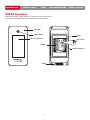
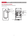
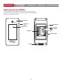
CAPXS Overview
Smart Video Intercom S (Model CAPXS) is a cloud based access control solution
that includes an integrated video camera enabling advanced video features.
DISPLAY (TOUCHSCREEN)
MICROPHONE
TERMINALS
SPEAKER
POWER
RESET BUTTON
ETHERNET CONNECTION
CAMERA WINDOW
POSTAL LOCK
SWITCH
N. O.
COM
WIEGAND
BLACK
GND
GREEN
DATA 0
WHITE
DATA 1
REX
GND
SUP
PRI. RLY.
N. O.
COM
N. C.
AUX. RLY.
N. O.
COM
N. C.
RESETPOWER ETHERNET

5
ACCOUNT SETUP NETWORK/MOUNTINGPOWER ACCESS CONTROLINTRODUCTION
INTRODUCTION ACCOUNT SETUP NETWORK/MOUNTINGPOWER ACCESS CONTROL
INTRODUCTION ACCOUNT SETUP NETWORK/MOUNTINGPOWER ACCESS CONTROL
INTRODUCTION ACCOUNT SETUP NETWORK/MOUNTINGPOWER ACCESS CONTROL
INTRODUCTION ACCOUNT SETUP NETWORK/MOUNTINGPOWER ACCESS CONTROL
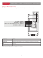
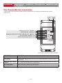
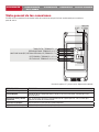
Connections Overview
The CAPXS has a combination of access control inputs/outputs that work in conjunction to control one access point.
INPUT/OUTPUT USED FOR
Postal Lock Input External post lock input.
Wiegand Input Standard 26-bit, 30-bit Wiegand, HID 37-bit with Facility Code, Transcore 37-bit, 32-bit MiFare.
Request to Exit & Supervised
Input REX: Used to request activation/release of door for exit purposes. SUP: Used to monitor door/gate
closed state.
Primary Relay Output Primary relay for door/gate release.
Auxiliary Relay Output Auxiliary relay for door/gate release.
NOTE: Only the 26-bit Wiegand protocol is compatible in UL installations.
PRIMARY RELAY - TERMINAL 9,10,11
POSTAL LOCK - TERMINAL 1,2
16 VDC
(+) Red GROUND
AUXILIARY RELAY TERMINAL 12,13,14
WIEGAND INPUT - TERMINAL 3,4,5
REQUEST TO EXIT (REX) & SUPERVISED INPUT (SUP) - TERMINAL 6,7,8
ETHERNET
(–) Black
See pages 15-16 for wiring diagrams.

6
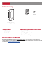
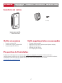
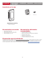
Tools Needed
• PH2 Phillips Screwdriver
• 1/8" Flat or PH0 Phillips Screwdriver
• T20 Torx Driver/Bit
PROVIDED (NOT SHOWN)
• Installation Manual
Carton Inventory
ACCOUNT SETUP NETWORK/MOUNTINGPOWER ACCESS CONTROLINTRODUCTION
INTRODUCTION ACCOUNT SETUP NETWORK/MOUNTINGPOWER ACCESS CONTROL
INTRODUCTION ACCOUNT SETUP NETWORK/MOUNTINGPOWER ACCESS CONTROL
INTRODUCTION ACCOUNT SETUP NETWORK/MOUNTINGPOWER ACCESS CONTROL
INTRODUCTION ACCOUNT SETUP NETWORK/MOUNTINGPOWER ACCESS CONTROL
CAPXL/CAPXLV
Power Supply
Goose-neck Gasket
PK625 Keys (2)
Ferrite Core
S10K30MOV
(Metal Oxide Varistor)(4)
1N4005 Diode Kit (4)
Torx Screw (2)
Radio Antenna (Security+ 2.0®)
and Cable
Wi-Fi® Antenna and Cable
Additional Tools Recommended
• Network LAN Cable Tester
• Wi-Fi Analyzer App (smartphone app)
• Network Analyzer software
• Computer with Ethernet port
• Flat Head Screws for Mounting
Preparation for Installation
Be prepared by downloading and completing our Installation Readiness Survey. Assess current internet connection details of the
community site prior to new unit or upgrade of an installation, and identify action items needed to proceed. You can find this helpful tool
at the following link: https://p.widencdn.net/oyeejd/114a4574.

7
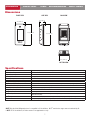
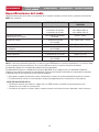
CAPXS Capacity Resident Capacity 500 / Local Event History 3,000
CAPXS Input Voltage 16 VDC +/-10%
Plug-in Supply Voltage 120 VAC, 60 Hz, 1 AMP, Class 2 output, Level VI efficiency
Operating Current 0.5A (typical) at 16VDC
CAPXS Operating Temperature Range - 20°C to 50°C (-4°F to 122°F)
Enclosure Polycarbonate
Storage and Shipping Temperature Range -40°C to 85°C (-40°F to 185°F)
Wiegand Input (1) 26-bit, *30-bit, *32-bit Mifare, *37-bit with and without facility code, and ASCII (for keypads)
1 Primary and 1 Auxiliary Relay Outputs SPDT, Rated Load 12 VDC, 10 AMP (each)
Accessory Compatibility Refer to the accessory page for compatible accessories
Network Compatibility 10/100 Ethernet
Wi-Fi® Compatibility 802.11b/g/n
Wi-Fi® Security CAPXS is compatible with routers using the following security protocols: WPA3 Personal and
WPA2 Personal (AES).
Wi-Fi® Range Up to 250 feet (76.2 m), Open Air/Line-of-Sight to front of panel (range will vary depending on obstructions)
CAPXS Video Camera** 1080p, Viewing angle - 135 degree diagonal, Up to 1,000 30-second temporary video events stored locally
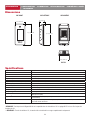
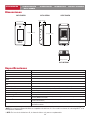
Dimensions
Specifications
FRONT VIEW SIDE VIEW BACK VIEW
BOTTOM VIEW
ACCOUNT SETUP NETWORK/MOUNTINGPOWER ACCESS CONTROLINTRODUCTION
INTRODUCTION ACCOUNT SETUP NETWORK/MOUNTINGPOWER ACCESS CONTROL
INTRODUCTION ACCOUNT SETUP NETWORK/MOUNTINGPOWER ACCESS CONTROL
INTRODUCTION ACCOUNT SETUP NETWORK/MOUNTINGPOWER ACCESS CONTROL
INTRODUCTION ACCOUNT SETUP NETWORK/MOUNTINGPOWER ACCESS CONTROL
*NOTE: Only the 26-bit Wiegand protocol is compatible in UL installations. Wi-Fi® and wireless ranges were not evaluated by UL.
**NOTE: For UL installations, the video camera is for supplement use only.
4 in (10.16 cm)
2 in (5.08 cm)
8 in (20.32 cm) 8 in (20.32 cm)
4 in (10.16 cm)
POSTAL LOCK
SWITCH
N. O.
COM
WIEGAND
BLACK
GND
GREEN
DATA0
WHITE
DATA1
REX
GND
SUP
PRI. RLY.
N. O.
COM
N. C.
AUX. RLY.
N. O.
COM
N. C.
RESETPOWER ETHERNET

8
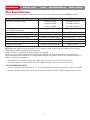
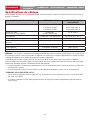
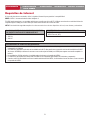
Wire Specifications
Use this chart to pull wires in preparation of your installation. Check the national and local building codes BEFORE installation.
DESCRIPTION OF WIRE RUN WIRE SPECIFICATION MAXIMUM RUN DISTANCE
Power Wire, secondary DC output 2-Conductor 14 AWG
2-Conductor 16 AWG
2-Conductor 18 AWG
Up to 300 feet (91.4 m)
Up to 200 feet (60.9 m)
Up to 100 feet (30.4 m)
Local Area Network (LAN)
CAT 5e or better Network Cable.
8-Conductor, 24 AWG Twisted pair 328 feet* (100 m)
Door Strike 2-Conductor 18-22 AWG Shielded 100 - 250 feet (30.5 - 76.2 m)
Magnetic Lock 2-Conductor 18-22 AWG 50 - 125 feet (15.2 - 38.1 m)
Dry Contact Closure (Most Gate Operators) 2-Conductor 18-24 AWG Shielded 500 - 2500 feet (152.4 - 762 m)
Exit Request (REX) 2-Conductor 18-24 AWG 500 feet (152.4 m)
Supervised Input 2-Conductor 18-24 AWG 500 feet (152.4 m)
Wiegand/Proximity Readers 3-Conductor 18-22 AWG Shielded 500 feet (152.4 m)
NOTE: Main power supply and control wiring MUST be run in separate conduits. Conduits must be UL approved for low and high
voltage. Refer to the NEC for additional wiring requirements.
Category 5e cabling is the minimum performance category recommended.
Wiring shall be in accordance with the National Electrical Code (ANSI/NFPA 70), local codes and authorities having jurisdiction.
Always provide power from a dedicated source. Plug provided transformer into an outlet wired to its own 10 Amp minimum circuit
breaker. This will prevent two problems:
• Other equipment cannot introduce spikes, noise, surges or dips into the power circuit that will affect the system.
• The system’s operation will not be affected if any other equipment develops a short circuit across the power line.
* CAT 5/6 NETWORK CABLE NOTES:
• For outdoor distances exceeding 140 feet (42.7 m), a UL497 compliant primary surge protector MUST be installed at the CAPXS.
• Distances exceeding 328 feet (100 m) may be accommodated with additional hardware (available through third-party sources).
ACCOUNT SETUP NETWORK/MOUNTINGPOWER ACCESS CONTROLINTRODUCTION
INTRODUCTION ACCOUNT SETUP NETWORK/MOUNTINGPOWER ACCESS CONTROL
INTRODUCTION ACCOUNT SETUP NETWORK/MOUNTINGPOWER ACCESS CONTROL
INTRODUCTION ACCOUNT SETUP NETWORK/MOUNTINGPOWER ACCESS CONTROL
INTRODUCTION ACCOUNT SETUP NETWORK/MOUNTINGPOWER ACCESS CONTROL

9
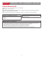
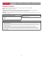
Internet Requirements
When selecting a router, use the information below to ensure compatibility.
MODEL: CAPXS - Smart Video Intercom S
CAPXS can be connected to a router via a wired connection or Wi-Fi. LiftMaster recommends a minimum upload/download speed of
5Mbps for each CAPXS supporting video camera feeds.
NOTE: This upload speed should be met when considering usage of other devices on the network like cameras and computers.
ACCOUNT SETUP NETWORK/MOUNTINGPOWER ACCESS CONTROLINTRODUCTION
INTRODUCTION ACCOUNT SETUP NETWORK/MOUNTINGPOWER ACCESS CONTROL
INTRODUCTION ACCOUNT SETUP NETWORK/MOUNTINGPOWER ACCESS CONTROL
INTRODUCTION ACCOUNT SETUP NETWORK/MOUNTINGPOWER ACCESS CONTROL
INTRODUCTION ACCOUNT SETUP NETWORK/MOUNTINGPOWER ACCESS CONTROL
CAPXS WI-FI SECURITY COMPATIBILITY
• WPA3 Personal
• WPA2 Personal (AES)
ADDITIONAL COMPATIBILITY CONSIDERATIONS:
• DO NOT use Wi-Fi extender devices. These may introduce latency in the connection leading to choppy or loss of reliable video transmission.
• If using a Wi-Fi signal strength tool or app, a continuous Wi-Fi signal strength connection of at least -65 DBM (numbers closer to zero are
stronger strength) at the CAPXS must be guaranteed to ensure an acceptable connection to the local network.
• Hidden network SSIDs are not supported. The network must be selectable from the CAPXS display.
• Wi-Fi networks requiring secondary authentication are not supported (E.g. Hotels and airport Wi-Fi).
• When checking signal strength in CAPXS admin mode, we recommend at least two bars, as shown on the CAPXS screen.
CAPXS IS COMPATIBLE WITH ROUTERS USING THE
FOLLOWING Wi-Fi COMMUNICATION PROTOCOLS:
• 802.11b
• 802.11g
• 802.11n

10
ACCOUNT SETUP NETWORK/MOUNTINGPOWER ACCESS CONTROLINTRODUCTION
INTRODUCTION ACCOUNT SETUP NETWORK/MOUNTINGPOWER ACCESS CONTROL
INTRODUCTION ACCOUNT SETUP NETWORK/MOUNTINGPOWER ACCESS CONTROL
INTRODUCTION ACCOUNT SETUP NETWORK/MOUNTINGPOWER ACCESS CONTROL
INTRODUCTION ACCOUNT SETUP NETWORK/MOUNTINGPOWER ACCESS CONTROL
Setup a myQ® Community Account
NOTE: If you have an existing myQ® account, your myQ® Community account will have the same
password. Go to: account.myQ.com and login.
If you do not have a myQ® Community account:
Method 1
1. Call LiftMaster Customer Care at 800.323.2276 to create a myQ® Community account.
2. You will get a welcome email from LiftMaster. Accept the invitation and register or login to your
account.
3. Setup the facility, select a subscription plan, add residents, and credentials (refer to the available
Help in myQ® Community).
4. Continue with the installation of the CAPXS in this manual.
Method 2
1. Navigate to https://www.myqbusiness.com/.
2. Click the Sign Up button.
3. Follow on screen steps to set-up a facility, select Community Manager, or Dealer, select subscription plan, add residents, and
credentials.
4. Continue with the installation of the CAPXS in this manual.
The following services are required for CAPXS to fully function
For Support, call 877.247.6764 or visit https://support.partner.liftmaster.com/s/community-access-support
NOTE: VoIP service is required for calling function. LiftMaster partners exclusively with Phone.com to provide the best integrated
solution for voice and video calling. Other VoIP providers are not compatible with our CAPXS.
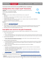
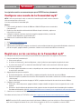
Signing up for myQ® Community Services
Service subscriptions are required for CAPXS to fully function. To sign up for services:
1. Set up a myQ Community account
a. Go to: account.myQ.com
b. If you don’t have a myQ® account, choose Sign Up and follow the prompts to complete account signup.
c. If you have an existing myQ® account, your myQ® Community account will have the same password. Choose Log In.
2. Create a new community
a. If you don’t have any communities in your account, you will be prompted to create a new community. Follow the prompts to
complete community creation.
3. Add devices/subscription plan
a. Under Device Management, select CAPXS and any other LiftMaster access control devices.
b. Subscription plan is pre-selected based on selected devices. Select any add-on services and check out.
c. Follow the prompts to finish adding CAPXS and any other LiftMaster acess control devices.
4. Configure the community
a. Under People—People Management, add residents. Also make sure to assign at least one access group to each resident.
b. Under People—Mobile App License Management, assign myQ Community App licenses to residents.
c. For more, visit https://support.partner.liftmaster.com/s/community-access-support/admins-and-community-managers.
5. Continue with the installation of the CAPXS in this manual.

11
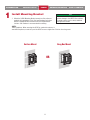
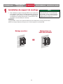
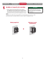
1. Mount the CAPXS Mounting Bracket securely to a flat surface or
pedestal with appropriate (1/4 in.) flat head hardware for Surface
Mount or appropriate #6 Flat Head screw for Gang Box Mount.
Stainless steel hardware is recommended for mounting.
NOTES:
-ADA Compliance: When mounting the CAPXS at a pedestrian entrance, to
meet ADA compliance, mount the top of the CAPXS screen no higher than 54 inches from the ground.
Install Mounting Bracket
1DO
Make sure the CAPXS is properly sealed to
prevent damage to the CAPXS from moisture.
For rough surfaces such as brick, additional
sealing will be needed.
ACCOUNT SETUP NETWORK/MOUNTINGPOWER ACCESS CONTROLINTRODUCTION
INTRODUCTION ACCOUNT SETUP NETWORK/MOUNTINGPOWER ACCESS CONTROL
INTRODUCTION ACCOUNT SETUP NETWORK/MOUNTINGPOWER ACCESS CONTROL
INTRODUCTION ACCOUNT SETUP NETWORK/MOUNTINGPOWER ACCESS CONTROL
INTRODUCTION ACCOUNT SETUP NETWORK/MOUNTINGPOWER ACCESS CONTROL
Surface Mount Gang Box Mount
OR

12
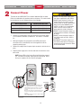
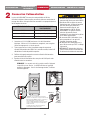
Connect Power
2• DO NOT use ANY power supply other
than those supplied with your CAPXS.
• DO NOT power electronic strikes and
latches with the same power supply
used to power the access control panel;
doing so will cause DAMAGE to the
CAPXS. Use ONLY a UL listed burglar
alarm or access control system to
power electronic strikes and latches.
• DO NOT connect the power supply to a
switched outlet or otherwise controlled
AC outlet.
• DO NOT connect the power supply to
the 120 Vac outlet until ALL wiring is
completed.
• DISCONNECT the power supply from
the 120 Vac outlet prior to inserting or
removing wires from the terminal block
to the Control Board.
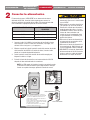
The outlet for the CAPXS MUST be an external dedicated 120 Vac outlet.
Refer to the table below for maximum wire run distances. This outlet should
be wired back to its own 10 Amp minimum circuit breaker.
1. Connect 14-18 AWG wire to the screw terminals on the power supply.
Use 2 conductor, Red/Black, jacketed wire. Use Red for + and Black
for -.
2. While pushing down the orange tab on the CAPXS power input
connector on the Control Board, insert the stripped wire into the
respective polarity input.
3. Release the orange tab on the power input connector to lock the wire in
place.
4. Plug the power supply into a 120 Vac outlet after all connections have
been made.
NOTE: Green LEDs on the Control Board will light when powered
up. The CAPXS will display a MyQ logo while booting up. When
boot up is complete, the user interface will appear.
ACCOUNT SETUP NETWORK/MOUNTINGPOWER ACCESS CONTROLINTRODUCTION
INTRODUCTION ACCOUNT SETUP NETWORK/MOUNTINGPOWER ACCESS CONTROL
INTRODUCTION ACCOUNT SETUP NETWORK/MOUNTINGPOWER ACCESS CONTROL
INTRODUCTION ACCOUNT SETUP NETWORK/MOUNTINGPOWER ACCESS CONTROL
INTRODUCTION ACCOUNT SETUP NETWORK/MOUNTINGPOWER ACCESS CONTROL
Dedicated 10 Amp Minimum Circuit
120 Vac
Dedicated Outlet
Power Supply
NOTE: If the power supply is installed outdoors, the
power supply must have its own approved NEMA 4
Rated weatherproof electrical enclosure. Use conduit
from the power supply enclosure to the controller
enclosure.
When the power supply (low voltage) wiring leaves the
enclosure, the wire must be rated for wet and damp
locations.
High voltage wiring must be run in a separate conduit
from low voltage wiring.
+ 16 VDC –
+ 16 VDC –
WIRE SPECIFICATION MAXIMUM RUN DISTANCE
14 AWG Up to 300 feet (91.4 m)
16 AWG Up to 200 feet (60.9 m)
18 AWG Up to 100 feet (30.4 m)

13
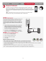
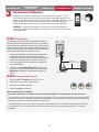
3Connect Internet
The CAPXS can connect to the Internet with a wired connection or with Wi-Fi® (wireless). See
page 9 for Internet requirements. If you are not in Admin Mode, press the 3 dots in the upper
right corner of the CAPXS display and enter the Admin Code, press the Network tab on the CAPXS
display, and press the “Change Network Settings” button. Follow the instructions according to your
application.
NOTE: The default Admin Code can be found in your myQ Business account. When you add a
CAPXS device to a facility, you will be prompted to create a new Admin Code.
ACCOUNT SETUP NETWORK/MOUNTINGPOWER ACCESS CONTROLINTRODUCTION
INTRODUCTION ACCOUNT SETUP NETWORK/MOUNTINGPOWER ACCESS CONTROL
INTRODUCTION ACCOUNT SETUP NETWORK/MOUNTINGPOWER ACCESS CONTROL
INTRODUCTION ACCOUNT SETUP NETWORK/MOUNTINGPOWER ACCESS CONTROL
INTRODUCTION ACCOUNT SETUP NETWORK/MOUNTINGPOWER ACCESS CONTROL
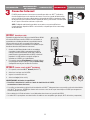
OPTION 1 Wired Connection
The Local Area Network (LAN) port is a 10/100 Ethernet interface with
an RJ45 jack for connecting the CAPXS to a hub, switch, or router
in order for it to gain connectivity to the Internet. Use a straight, (i.e.,
non-crossover) Cat5e, or Cat6 cable to connect to a local hub, switch
or router. This type of cable is referred to as an Ethernet cable in this
manual.
1. Connect an Ethernet cable from the hub, switch, or router to the
LAN port on the back of the CAPXS. When connected properly,
the green and amber LED on the Ethernet port on the back of
the CAPXS will light/flicker. If the green LED is not lit, check the
connections on the CAPXS and the Ethernet hub.
2. On the display, select Wired Network if dynamic configuration
(DHCP) is desired or select Manual Setup for a static IP address.
OPTION 2 Connect through Wi-Fi® (Wireless)
1. On the display select Wi-Fi® Network.
2. Select the network the CAPXS will use.
3. Enter the password for the network.
4. Select Login.
Additional compatibility considerations:
• When checking signal strength in CAPXS admin mode, we recommend at least two bars.
• If using a Wi-Fi® signal strength tool or app, a continuous Wi-Fi® signal strength connection
of at least -65 dBm (numbers closer to zero are stronger strength) at the CAPXS must be guaranteed to ensure an acceptable
connection to the local network.
• Hidden network SSIDs are not supported. The network must be selectable from the CAPXS display.
• Wi-Fi® networks requiring secondary authentication are not supported (E.g. Hotels and airport Wi-Fi®).
Modem
Router/Switch
Ethernet Cable
(325 feet [99.1 m] maximum)
-30 to -67
dBm
GOOD
-66 to -85
dBm
POSSIBLE
≤ -86
dBm
POOR
-30 to -67
dBm
GOOD
-66 to -85
dBm
POSSIBLE
≤ -86
dBm
POOR
-30 to -67
dBm
GOOD
-66 to -85
dBm
POSSIBLE
≤ -86
dBm
POOR

14
ACCOUNT SETUP NETWORK/MOUNTINGPOWER ACCESS CONTROLINTRODUCTION
INTRODUCTION ACCOUNT SETUP NETWORK/MOUNTINGPOWER ACCESS CONTROL
INTRODUCTION ACCOUNT SETUP NETWORK/MOUNTINGPOWER ACCESS CONTROL
INTRODUCTION ACCOUNT SETUP NETWORK/MOUNTINGPOWER ACCESS CONTROL
INTRODUCTION ACCOUNT SETUP NETWORK/MOUNTINGPOWER ACCESS CONTROL
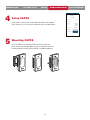
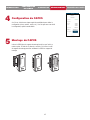
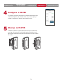
On the display, select each tab in Admin Mode to validate setup (network,
inputs, outputs, etc.). Once you have validated the setup, exit Admin Mode.
Setup CAPXS
4
Insert the CAPXS in the mounting bracket until the unit snaps into
place. Using screws provided, tighten the screws through the side of the
mounting bracket to securely affix the CAPXS to the Mounting Bracket.
Mounting CAPXS
5

15
+
–
+
–
PUSH
BUTTON
DOOR STRIKE
MAGLOCK
PROXIMITY
SENSOR
For DC Power:
Install a 1N4005
diode or equivalent
Use 18-22 AWG
Power for Maglock
(Not Provided)
DO NOT use the power
supply for the controller
Use 18-22 AWG
For DC Power:
Install a 1N4005
diode or equivalent
Power for Door Strike
(Not Provided)
REQUEST TO EXIT
REQUEST TO EXIT (REX)
GROUND (BLACK GND)
POWER
GROUND
DATA 0 (GREEN DATA0)
DATA 1 (WHITE DATA1)
GROUND
SUPERVISED GROUND (GND)
SUPERVISED
NORMALLY OPEN (N.O)
COMMON (COM)
NORMALLY OPEN (N.O.)
COMMON (COM)
NORMALLY CLOSED (N.C.)
NORMALLY OPEN (N.O.)
COMMON (COM)
NORMALLY OPEN
COMMON
NORMALLY CLOSED
COMMON
OR
OR
REQUEST TO EXIT
POWER
POSTAL LOCK**
*PRIMARY RELAY
ALARM BYPASS
NORMALLY OPEN
COMMON
AUXILIARY RELAY
ETHERNET CONNECTION
OR
NOTE: The length of the unshielded
wires should be kept to a minimum to
avoid electrical noise.
NOTE: For KPR2000 keypad
wire the pink and black (ground)
wires together.
READER
OR
KEYPAD
12 VDC POWER SUPPLY
WIEGAND
LIGHT
LOAD
LINE
NEUTRAL
Isolation
Relay
Low
Voltage
Power
Supply
For AC Power:
Install a Siemens S10K30MOV
(Metal Oxide Varistor) or
equivalent
For AC Power:
Install a Siemens
S10K30MOV
(Metal Oxide Varistor) or
equivalent
* NOTE: MAGLOCK, door strike and
ALARM BYPASS not evaluated by UL.
NOTE: DO NOT
connect high
voltage power
to the CAPXS
unit.
POSTAL LOCK
** NOTE: For more information on how
to wire in a postal lock, refer to the
manual for accessory: CAPXSTKPL.
SUPERVISED
(DOOR STATUS)
DOOR SENSOR
(SUPERVISED)
DOOR SENSOR
(NON-SUPERVISED)
OR
EOL (End of Line) Resistor
(1k ohm)
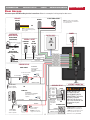
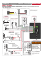
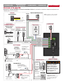
Door Access
Disconnect power BEFORE making electrical connections. Below is an example of a wiring setup for door access.
ACCOUNT SETUP NETWORK/MOUNTINGPOWER ACCESS CONTROLINTRODUCTION
INTRODUCTION ACCOUNT SETUP NETWORK/MOUNTINGPOWER ACCESS CONTROL
INTRODUCTION ACCOUNT SETUP NETWORK/MOUNTINGPOWER ACCESS CONTROL
INTRODUCTION ACCOUNT SETUP NETWORK/MOUNTINGPOWER ACCESS CONTROL
INTRODUCTION ACCOUNT SETUP NETWORK/MOUNTINGPOWER ACCESS CONTROL
DO NOT INSTALL THE
SYSTEM IN THE FAIL
SECURE MODE UNLESS
PERMITTED BY THE LOCAL
AUTHORITY HAVING
JURISDICTION. Doing so
may cause interference with
the operation of panic
hardware.

16
ACCOUNT SETUP NETWORK/MOUNTINGPOWER ACCESS CONTROLINTRODUCTION
INTRODUCTION ACCOUNT SETUP NETWORK/MOUNTINGPOWER ACCESS CONTROL
INTRODUCTION ACCOUNT SETUP NETWORK/MOUNTINGPOWER ACCESS CONTROL
INTRODUCTION ACCOUNT SETUP NETWORK/MOUNTINGPOWER ACCESS CONTROL
INTRODUCTION ACCOUNT SETUP NETWORK/MOUNTINGPOWER ACCESS CONTROL
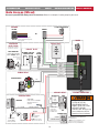
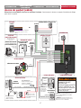
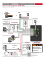
Gate Access (Wired)
Disconnect power BEFORE making electrical connections. Below is an example of a wiring setup for gate access.
GROUND
POWER
GROUND
DATA 0
DATA 1
POWER
ETHERNET CONNECTION
POSTAL LOCK
POSTAL LOCK**
NOTE: For KPR2000 keypad
wire the pink and black (ground)
wires together.
READER
KEYPAD
WIEGAND
+
–
NORMALLY OPEN
COMMON
NORMALLY OPEN
NORMALLY CLOSED
COMMON
REQUEST TO EXIT
GROUND
NORMALLY OPEN
COMMON
PUSH
BUTTON
MAGLOCK
12 VDC POWER SUPPLY
OR
EXTERNAL FREE EXIT
LOOP DETECTOR
For DC Power:
Install a 1N4005
diode or equivalent
Use 18-22 AWG
Power for Maglock
(Not Provided)
DO NOT use the power
supply for the controller
For AC Power:
Install a Siemens S10K30MOV
(Metal Oxide Varistor) or
equivalent
NORMALLY CLOSED
COMMON
OR
REQUEST TO EXIT
PRIMARY RELAY
*AUXILIARY RELAY
GATE OPERATOR
COMMON
EXIT
ALARM BYPASS
LIGHT
NORMALLY OPEN
COMMON
LOAD
LINE
AUXILIARY RELAY
OR
NEUTRAL
** NOTE: For more information on how
to wire in a postal lock, refer to the
manual for accessory: CAPXSTKPL.
* NOTE: MAGLOCK and ALARM BYPASS
not evaluated by UL.
NOTE: DO NOT
connect high
voltage power to
the CAPXS unit.
Isolation
Relay
Low
Voltage
Power
Supply
GATE OPERATOR
(connect to Aux Closed Limit
switch - refer to gate operator
manual)
SUPERVISED
(GATE STATUS)
(Not applicable for wireless
gate operator connections)
EOL (End of Line)
Resistor
(1k ohm)
SUP
DO NOT INSTALL THE
SYSTEM IN THE FAIL
SECURE MODE UNLESS
PERMITTED BY THE LOCAL
AUTHORITY HAVING
JURISDICTION. Doing so may
cause interference with the
operation of panic hardware.

17
RESET BUTTON
NOTE: It is recommended to reset the CAPXS to factory defaults by using the Factory Reset option in the Admin Mode. In the event you
have forgotten the Admin Code, or the display has become unresponsive, you can manually reset the CAPXS using the Reset Button.
To manually reset the CAPXS: With the CAPXS powered on, press and hold the Reset Button for 3 seconds. The CAPXS will reboot and
restore factory default settings.
NOTE: Resetting to factory default setting will erase Network settings. Have the Network configuration information available to be re-
entered once the reset completes.
ACCOUNT SETUP NETWORK/MOUNTINGPOWER ACCESS CONTROLINTRODUCTION
INTRODUCTION ACCOUNT SETUP NETWORK/MOUNTINGPOWER ACCESS CONTROL
INTRODUCTION ACCOUNT SETUP NETWORK/MOUNTINGPOWER ACCESS CONTROL
INTRODUCTION ACCOUNT SETUP NETWORK/MOUNTINGPOWER ACCESS CONTROL
INTRODUCTION ACCOUNT SETUP NETWORK/MOUNTINGPOWER ACCESS CONTROL

1818
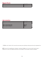
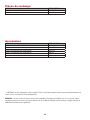
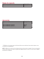
Accessories
ITEM PART NUMBER
Mounting Bracket, CAPXS K41-0273-000
Power Supply Kit K041-0353-000
ITEM PART NUMBER
Reader Multi-class SE RP10 Mini Mullion LMMC-MINI
CAPXS, Hood CAPXSHOOD
CAPXS, Trim Kit with Postal Lock CAPXSTKPL
CAPXS, Trim Kit w/o Postal Lock CAPXSTK
Wiegand Keypad/Proximity Reader KPR2000*
Connected Access Portal 2 Door CAP2D
Repair Parts
* KPR2000 is not UL listed to UL 294. It cannot be used as primary means of granting or denying access but only for supplemental use.
NOTE: A current list of compatible readers and keypads is maintained at LiftMaster.com. If you have a specific model of reader or
keypad that is not listed on the LiftMaster website, please contact LiftMaster Technical Support to determine compatibility.

19
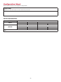
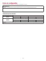
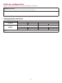
Configuration Sheet
Record device information and configuration settings below.
CAPXS Name:
NOTE: Any user of the system is subject to the terms outlined in the product EULA.
Notes:
DEVICE CONFIGURATION:
DOOR 1 DOOR/GATE NAME:
INPUTS WIEGAND REX STATUS/SUP
EOL (Y / N)
OUTPUTS
PRIMARY RELAY AUXILIARY RELAY
N.O. N.C. N.O. N.C.
Notes:

20
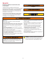
Legal Disclaimers
Canada-Underwriters Laboratories Compliance
The CAPXS shall be installed in accordance with Part 1 of the Canadian Electrical Code.
Documentation Disclaimer and Restrictions
Information in this document is subject to change without notice and does not represent a commitment on the part of LiftMaster. For the
most up-to-date information, visit LiftMaster.com.
This document and the data herein shall not be duplicated, used or disclosed to others for procurement or manufacturing, except
as authorized with the written permission of LiftMaster. The information contained within this document or within the product itself
is considered the exclusive property of LiftMaster. All information in this document or within the hardware and software product
themselves is protected by the copyright and/or other intellectual property laws of the United States.
Endurance: Level 4, Line security: Level 1, Destructive Attack: Level 1, Power Standby: Level 1
NOTICE: This device complies with part 15 of the FCC rules and Innovation, Science and Economic Development Canada license-exempt RSSs. Operation is subject to the following two conditions: (1) this device may not cause
harmful interference, and (2) this device must accept any interference received, including interference that may cause undesired operation. Any changes or modifications not expressly approved by the party responsible for
compliance could void the user’s authority to operate the equipment.
This device must be installed to ensure a minimum 20 cm (8 in.) distance is maintained between users/bystanders and device.
This device has been tested and found to comply with the limits for a Class B digital device, pursuant to part 15 of the FCC rules and Industry Canada ICES standard. These limits are designed to provide reasonable protection
against harmful interference in a residential installation. This equipment generates, uses and can radiate radio frequency energy and, if not installed and used in accordance with the instructions, may cause harmful interference
to radio communications.
However, there is no guarantee that interference will not occur in a particular installation. If this equipment does cause harmful interference to radio or television reception, which can be determined by turning the equipment
off and on, the user is encouraged to try to correct the interference by one or more of the following measures:
- Reorient or relocate the receiving antenna.
- Increase the separation between the equipment and receiver.
- Connect the equipment into an outlet on a circuit different from that to which the receiver is connected.
- Consult the dealer or an experienced radio/TV technician for help.
NOTICE: When mounting the CAPXS at a pedestrian entrance, to meet ADA compliance, mount the top of the CAPXS screen no higher than 54 inches from the ground.
NOTE: When installing CAPXS, please refer to the local jurisdiction for any specific requirements such as physical signage that may be
required.
FCC CAUTION
Changes or modifications not expressly approved by the party responsible for compliance could void the user’s authority to operate
equipment.
Compliance with FCC requirement 15.407(c)
Data transmision is always initiated by software, which is then passed down through the MAC, through the digital and analog baseband,
and finally to the RF chip. Several special packets are initiated by the MAC. These are the only ways the digital baseband portion will
turn on the RF transmitter, which it then turns off at the end of the packet. Therefore, the transmitter will be on only while one of the
aforementioned packets is being transmitted. In other words, this device automatically discontinues transmission in case of either
absence of information to transmit or operational failure.
Frequency Tolerance: +/-20 p.p.m.
This transmitter must not be co-located or operated in conjunction with any other antenna or transmitter.
To access Device Compliance Information for FCC and IC, click on the “i” in the upper left hand corner of the Home Screen on the
CAPXS.
La page charge ...
La page charge ...
La page charge ...
La page charge ...
La page charge ...
La page charge ...
La page charge ...
La page charge ...
La page charge ...
La page charge ...
La page charge ...
La page charge ...
La page charge ...
La page charge ...
La page charge ...
La page charge ...
La page charge ...
La page charge ...
La page charge ...
La page charge ...
La page charge ...
La page charge ...
La page charge ...
La page charge ...
La page charge ...
La page charge ...
La page charge ...
La page charge ...
La page charge ...
La page charge ...
La page charge ...
La page charge ...
La page charge ...
La page charge ...
La page charge ...
La page charge ...
La page charge ...
La page charge ...
La page charge ...
La page charge ...
La page charge ...
La page charge ...
La page charge ...
La page charge ...
-
 1
1
-
 2
2
-
 3
3
-
 4
4
-
 5
5
-
 6
6
-
 7
7
-
 8
8
-
 9
9
-
 10
10
-
 11
11
-
 12
12
-
 13
13
-
 14
14
-
 15
15
-
 16
16
-
 17
17
-
 18
18
-
 19
19
-
 20
20
-
 21
21
-
 22
22
-
 23
23
-
 24
24
-
 25
25
-
 26
26
-
 27
27
-
 28
28
-
 29
29
-
 30
30
-
 31
31
-
 32
32
-
 33
33
-
 34
34
-
 35
35
-
 36
36
-
 37
37
-
 38
38
-
 39
39
-
 40
40
-
 41
41
-
 42
42
-
 43
43
-
 44
44
-
 45
45
-
 46
46
-
 47
47
-
 48
48
-
 49
49
-
 50
50
-
 51
51
-
 52
52
-
 53
53
-
 54
54
-
 55
55
-
 56
56
-
 57
57
-
 58
58
-
 59
59
-
 60
60
-
 61
61
-
 62
62
-
 63
63
-
 64
64


dans d''autres langues
- English: LiftMaster CAPXS User manual
- español: LiftMaster CAPXS Manual de usuario
Documents connexes
Autres documents
-
myQ VKP1-LM MC Mode d'emploi
-
Mircom LT-6046 DO-CR3 Mode d'emploi
-
 Minebea Intec Modèles CAPXS.. Plates-formes de pesée en acier inoxydable pour domaines à risques d’explosions Le manuel du propriétaire
-
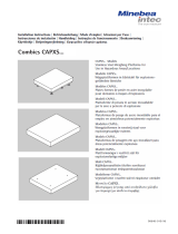 Minebea Intec CAPXS.. Models Stainless Steel Weighing Platforms for Use in Hazardous Areas/Locations Le manuel du propriétaire
-
 Minebea Intec YDO07-X Datenausgang für Combics-Ex Le manuel du propriétaire
-
Farpointe Data CONEKT5 Mode d'emploi
-
-
LifeMaster CAPXLCAM Manuel utilisateur
-
Chamberlain 8550W Manuel utilisateur
-
LifeMaster SL3000UL Slide Manuel utilisateur


