E-flite EFL71750 Le manuel du propriétaire
- Catégorie
- Jouets télécommandés
- Taper
- Le manuel du propriétaire
Ce manuel convient également à

DX Series Transmitter Setup
1. Power ON your transmitter, click on scroll wheel, roll to System Setup and click the
scroll wheel. Choose yes.
2. Go to Model Select and choose <Add New Model> at the bottom of the list. The
system asks if you want to create a new model, select Create
3. Set Model Type: Select Airplane Model Type by choosing the airplane.
The system asks you to conrm model type, data will be reset. Select YES
4. Set Model Name: Input a name for your model le
5. Scroll to Aircraft type, click on the roller. Scroll to Wing: click on the roller and scroll
to select 1Ail 1Flap.
6. Select <Main Screen>, Click the scroll wheel to enter the Function List
7. Set D/R (Dual Rate) and Expo; Aileron
Set Switch: Switch F
Set High Rates: 100%, Expo 10% - Low Rates: 70%, Expo 5%
8. Set D/R (Dual Rate) and Expo; Elevator
Set Switch: SWITCH C
Set High Rates: 100%, Expo 10% - Low Rates 70%, Expo 5%
9. Scroll to Throttle Cut; Switch: Switch H, Position: -100%
10. Scroll to Flap System
Set SWITCH D
Set POS 0: 0% FLAP 0% Elevator
Set POS 1: 38% FLAP 3% Elevator
Set POS 2: 68% FLAP 9% Elevator
Set SPEED 2.0s
iX Series Transmitter Setup
1. Power ON your transmitter and begin once the Spektrum Airware app is open.
Select the orange pen icon in the upper left corner of the screen, the system asks for
permission to Turn Off RF, select PROCEED
2. Select the three dots in the upper right corner of the screen,
select Add a New Model
3. Select Model Option, choose DEFAULT, select Airplane.
The system asks if you want to create a new acro model, select Create
4. Select the last model on the list, named Acro.
Tap on the word Acro and rename the le to a name of your choice
5. Tap and hold the back arrow icon in the upper left corner of the screen to return to the
main screen
6. Go to Model Setup menu. Select Aircraft Type The system asks for permission to
Turn Off RF, select PROCEED.
Touch the screen to select wing. Select 1 Ail 1 Flap.
7. Press and hold the back arrow icon in the upper left corner of the screen to return to
the main screen.
8. Go to the Model Adjust menu
9. Set Dual Rates and Expo; Select Aileron
Set Switch: Switch F
Set High Rates: 100%, Expo 10% - Low Rates: 70%, Expo 5%
10. Set Dual Rates and Expo; Select Elevator
Set Switch: SWITCH C
Set High Rates: 100%, Expo 10% - Low Rates 70%, Expo 5%
11. Select Flap System
Set SWITCH D
Set POS 0: 0% FLAP 0% Elevator
Set POS 1: 38% FLAP 3% Elevator
Set POS 2: 68% FLAP 9% Elevator
Set SPEED 2.0s
12. Select Throttle Cut; Switch: Switch H, Position: -100%
NX Series Transmitter Setup
1. Power ON your transmitter, click on scroll wheel, roll to System Setup and click the
scroll wheel. Choose yes.
2. Go to Model Select, click on the scroll wheel, and choose <Add New Model> near the
bottom of the list. Select Airplane Model Type by choosing the airplane, select Create
3. Set Model Name: Input a name for your model le
4. Scroll to Aircraft type, click on the roller. Scroll to Wing: click on the roller and scroll to
select 1Ail 1Flap.
5. Select <Main Screen>, Click the scroll wheel to enter the Function List
6. Set Rates and Expo; Aileron
Set Switch: Switch F
Set High Rates: 100%, Expo 10% - Low Rates: 70%, Expo 5%
7. Set Rates and Expo; Elevator
Set Switch: SWITCH C
Set High Rates: 100%, Expo 10% - Low Rates 70%, Expo 5%
8. Scroll to Throttle Cut; Switch: Switch H, Position: -100%
9. Scroll to Flap System
Set SWITCH D
Set POS 0: 0% FLAP 0% Elevator
Set POS 1: 38% FLAP 3% Elevator
Set POS 2: 68% FLAP 9% Elevator
Set SPEED 2.0s
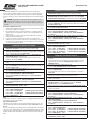
Turbo Timber SWS 2.0m BNF Basic and ARF
Manual Addendum
EFL71765, EFL71750
EN Flap Setup
The transmitter setup tables in the printed manual were incorrect. Use the following tables to
correctly set the Aircraft Type and Flap System values. Follow the Flap Setup Procedure below
to test the ap system function before attempting ight.
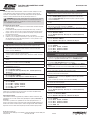
Flap Setup Procedure
1. Before powering the model, disconnect the ap pushrod clevises from the ap control
horns.
2. With the ap switch in the up position (Pos 0: 0% travel), power the model and verify
the servo arms are perpendicular to the wing surface.
3. Adjust the clevises as needed to align each ap with the xed inner portion of the wing
trailing edge.
4. Reconnect the clevises to the ap horns, and secure with the tubing.
5. Verify ap travel is 22mm (Pos 1), and 45mm (Pos 2). It may be necessary to make
small adjustments to the Pos 1 and Pos 2 ap travel settings to achieve this.
Propeller
The correct propeller size for this model is the included 15 x 8E (EFLP71764). Disregard any
references to other sizes.
Motor/Thrust Reverse
The included ESC requires an update to enable the thrust reversing feature. This can be
accomplished with the use of a Spektrum Programming Box (SPMXCA200) and Windows PC.
Alternately, a programming card can be provided to you at no charge. If you prefer this
option, send an email request to productsupport@horizonhobby.com. Include a photo of your
purchase receipt, and Turbo Timber SWS ESC Programmer in the subject line. Our Product
Support team will send this as soon as possible.

Turbo Timber SWS 2.0m BNF Basic and ARF
Ergänzung zum Handbuch
EFL71765, EFL71750
Konguration von Sendern der DX-Serie
1. Schalten Sie Ihren Sender EIN, klicken Sie das Scrollrad an, gehen Sie auf
Systemkonguration und klicken das Scrollrad an. Wählen Sie Ja.
2. Gehen Sie auf Modellauswahl und wählen Sie <Neues Modell hinzufügen> ganz
unten in der Liste. Das System fragt, ob Sie ein neues Modell erstellen möchten,
wählen Sie Erstellen
3. Modelltyp einstellen: Wählen Sie Flugzeugmodelltyp durch Auswählen des
Flugzeugs.
Das System bittet Sie, den Modelltyp zu bestätigen. Die Daten werden zurückgesetzt.
JA auswählen
4. Modellnamen einstellen: Geben Sie einen Namen für Ihre Modelldatei ein
5. Scrollen Sie auf Luftfahrzeugtyp, klicken Sie auf das Scrollrad. Scrollen Sie
auf Tragäche: klicken Sie auf das Scrollrad und scrollen Sie zur Auswahl von
1Querruder 1 Klappe.
6. Wählen Sie <Hauptbildschirm>, Klicken Sie das Scrollrad an, um zur Funktionsliste
zu gelangen
7. Stellen Sie D/R (Dualrate) und Expo; Querruder ein
Stellen Sie Schalter ein: Schalter F
Stellen Sie ein Hohe Geschwindigkeiten: 100%, Expo 10% - Niedrige
Geschwindigkeiten: 70%, Expo 5%
8. Stellen Sie D/R (Dualrate) und Expo; Höhenruder ein
Stellen Sie ein Schalter: SCHALTER C
Stellen Sie ein Hohe Geschwindigkeiten: 100%, Expo 10% - Niedrige
Geschwindigkeiten 70%, Expo 5%
9. Scrollen Sie auf Gasabschaltung; Schalter: Schalter H, Position: -100%
10. Scrollen Sie auf Klappensystem
Stellen Sie ein SCHALTER D
Stellen Sie ein POS 0: 0% KLAPPE 0% Höhenruder
Stellen Sie ein POS 1: 38% KLAPPE 3% Höhenruder
Stellen Sie ein POS 2: 68% KLAPPE 9% Höhenruder
GESCHWINDIGKEIT 2,0s einstellen
Konguration von Sendern der iX-Serie
1. Schalten Sie Ihren Sender EIN und beginnen Sie, sobald die App Spektrum Airware
geöffnet ist.
Wählen Sie das orangene Stiftsymbol oben links auf dem Bildschirm. Das System
erfragt eine Erlaubnis zum Ausschalten HF, wählen Sie FORTFAHREN
2. Wählen Sie die drei Punkte oben rechts auf dem Bildschirm.
Wählen Sie Neues Modell hinzufügen
3. Gehen Sie auf Modelloption, wählen Sie STANDARDMÄSSIG, wählen Sie Flugzeug.
Das System fragt, ob Sie ein neues Acro-Modell erstellen möchten, wählen Sie
Erstellen
4. Wählen Sie das letzte Modell in der Liste aus, das Acro heißt.
Klicken Sie das Wort Acro an und geben Sie der Datei einen neuen Namen Ihrer Wahl.
5. Klicken Sie auf das Symbol schwarzer Zurück-Pfeil oben links auf dem Bildschirm, um
zum Hauptbildschirm zurückzukehren
6. Rufen Sie das Menü Modelleinstellungen auf. Wählen Sie den Flugzeugtyp Das
System fragt nach der Erlaubnis, um RF auszuschalten, wählen Sie WEITER.
Berühren Sie den Bildschirm, um eine Tragäche auszuwählen. 1 Querruder 1 Klappe
auswählen.
7. Drücken und halten Sie das Pfeil-zurück-Symbol in der oberen linken Ecke des
Bildschirms, um zum Hauptbildschirm zurückzukehren.
8. Zum Menü Anpassen des Modells gehen
9. Stellen Sie ein Dualrate und Expo; Wählen Sie Querruder
Stellen Sie ein Schalter: Schalter F
Stellen Sie ein Hohe Geschwindigkeiten: 100%, Expo 10% - Niedrige
Geschwindigkeiten: 70%, Expo 5%
10. Stellen Sie Dualrate und Expo ein; Wählen Sie Höhenruder
Stellen Sie Schalter ein: SCHALTER C
Stellen Sie ein Hohe Geschwindigkeiten: 100%, Expo 10% - Niedrige
Geschwindigkeiten 70%, Expo 5%
11. Wählen Sie Klappensystem
Stellen Sie ein SCHALTER D
Stellen Sie ein POS 0: 0% KLAPPE 0% Höhenruder
Stellen Sie ein POS 1: 38% KLAPPE 3% Höhenruder
Stellen Sie ein POS 2: 68% KLAPPE 9% Höhenruder
GESCHWINDIGKEIT 2,0s einstellen
12. Wählen Sie Gasabschaltung; Schalter: Schalter H, Position: -100%
Konguration von Sendern der NX-Serie
1. Schalten Sie Ihren Sender EIN, klicken Sie das Scrollrad an, gehen Sie auf
Systemkonguration und klicken das Scrollrad an. Wählen Sie Ja.
2. Gehen Sie auf Modellauswahl, klicken Sie auf das Scrollrad und wählen Sie <Neues
Modell hinzufügen> unten in der Liste. Wählen Sie Luftfahrzeugtyp durch Auswählen
des Flugzeugs, wählen Sie Erstellen
3. Modellnamen einstellen: Geben Sie einen Namen für Ihre Modelldatei ein
4. Scrollen Sie auf Luftfahrzeugtyp, klicken Sie auf das Scrollrad. Scrollen Sie auf
Tragäche: klicken Sie auf das Scrollrad und scrollen Sie zur Auswahl von 1Querruder
1 Klappe.
5. Wählen Sie <Hauptbildschirm>, Klicken Sie das Scrollrad an, um zur Funktionsliste
zu gelangen
6. Stellen Sie ein Dualrate und Expo; Querruder
Stellen Sie ein Switch: Schalter F
Stellen Sie ein Hohe Geschwindigkeiten: 100%, Expo 10% - Niedrige
Geschwindigkeiten: 70%, Expo 5%
7. Stellen Sie ein Dualrate und Expo; Höhenruder
Stellen Sie ein Schalter: SCHALTER C
Stellen Sie ein Hohe Geschwindigkeiten: 100%, Expo 10% - Niedrige
Geschwindigkeiten 70%, Expo 5%
8. Scrollen Sie auf Gasabschaltung; Schalter: Schalter H, Position: -100%
9. Scrollen Sie auf Klappensystem
Stellen Sie ein SCHALTER D
Stellen Sie ein POS 0: 0% KLAPPE 0% Höhenruder
Stellen Sie ein POS 1: 38% KLAPPE 3% Höhenruder
Stellen Sie ein POS 2: 68% KLAPPE 9% Höhenruder
GESCHWINDIGKEIT 2,0s einstellen
DE Einstellung der Klappen
Die Sender-Einstelltabellen im gedruckten Handbuch waren fehlerhaft. Verwenden Sie
die folgenden Tabellen zur korrekten Einstellung des Luftfahrzeugtyps und der Werte des
Klappensystems. Folgen Sie dem nachstehenden Vorgang zur Einstellung der Klappen, um
das Funktionieren des Klappensystems vor dem Flug zu testen.
ACHTUNG: Der Servo-Betrieb muss vor dem Flug stets überprüft werden. Wenn der
Servo durch Ihre Einstellungen zu weit bewegt wird und die Gestänge blockiert
werden, kann dies zu einer übermäßigen Stromaufnahme führen, die einen Kontrollverlust
verursachen kann.
Vorgang zur Einstellung der Klappen
1. Bevor Sie das Modell einschalten, trennen Sie die Gabelköpfe von den Steuerhörnern
der Klappe.
2. Mit dem Klappenschalter in der oberen Position (Pos 0: 0% Verfahrweg), schalten
Sie das Modell ein und überprüfen Sie, dass die Servoarme senkrecht zur Tragäche
stehen.
3. Passen Sie die Gabelköpfe nach Bedarf an, um jede Klappe mit dem festen inneren Teil
der Flügelhinterkante auszurichten.
4. Verbinden Sie die Gabelköpfe wieder mit den Klappen-Steuerhörnern und sichern Sie
sie mit den Schläuchen.
5. Überprüfen, dass der Klappen-Verfahrweg 22 mm (Pos 1), und 45 mm (Pos 2) beträgt.
Es kann erforderlich sein, die Einstellungen des Klappen-Verfahrwegs Pos 1 und Pos 2
leicht anzupassen, um diese Werte zu erreichen.
Propeller
Die korrekte Propellergröße für dieses Modell ist die mitgelieferte Größe 15 x 8E (EFLP71764).
Hinweise auf andere Größen sind zu ignorieren.
Motor/Schubumkehr
Der mitgelieferte Geschwindigkeitsregler muss aktualisiert werden, um die Schubumkehr-
Funktion zu aktivieren. Dies kann mithilfe einer Spektrum Programmierbox (SPMXCA200) und
einem Windows PC erreicht werden.
Als Alternative kann Ihnen eine Programmierkarte kostenlos zur Verfügung gestellt werden.
Wenn Sie diese Option bevorzugen, senden Sie per E-Mail eine Anfrage an productsupport@
horizonhobby.com. Fügen Sie ein Foto des Kaufbelegs bei und geben Sie and Turbo Timber
SWS ESC Programmer als Betreff an. Unser Produkt-Support-Team wird Ihnen diese Karte so
schnell wie möglich zusenden.

Turbo Timber SWS 2.0m BNF Basic and ARF
Addenda au manuel
EFL71765, EFL71750
Conguration d’un émetteur de la série DX
1. Mettez l’émetteur en marche, cliquez sur la molette, allez à System Setup
(Conguration du système) et cliquez sur la molette. Choisissez Yes (Oui).
2. Allez à Model Select (Sélectionner un modèle) et choisissez <Add New Model>
(Ajouter un nouveau modèle) au bas de la liste. Le système demande si vous voulez
créer un nouveau modèle, sélectionnez Create (Créer).
3. Dénissez le Model Type (Type de modèle): Sélectionnez Airplane Model Type
(Type de modèle d’avion) en choisissant l’avion.
Le système vous demande de conrmer le type de modèle, les données seront
réinitialisées. Sélectionnez YES (OUI).
4. Dénissez le Model Name (Nom du modèle): entrez un nom pour votre chier de
modèle.
5. Faites déler jusqu’à Aircraft Type (Type d’aéronef) et cliquez sur la molette. Faites
déler jusqu’à Wing (Aile): cliquez sur la molette et faites déler pour sélectionner 1
Ail 1 Flap (1aileron 1volet).
6. Sélectionnez <Main Screen> (Écran principal), cliquez sur la molette pour entrer
dans la Function List (Liste des fonctions).
7. Dénissez D/R (Double débattement) et Expo; Aileron
Dénissez Switch (Commutateur): SwitchF (CommutateurF)
Dénissez Grands débattements: 100%, Expo 10% – Faibles débattements:
70%, Expo 5%
8. Choisissez D/R (Double débattement) et Expo; Elevator (Gouverne de profondeur)
Dénissez Switch (Commutateur): SwitchC (CommutateurC)
Dénissez Grands débattements: 100%, Expo 10% – Faibles débattements:
70%, Expo 5%
9. Faites déler jusqu’à Throttle Cut (Manette des gaz); Switch (Commutateur):
SwitchH (CommutateurH), Position: -100%
10. Faites déler jusqu’à Flap System (Système de volets).
Dénissez SwitchD (CommutateurD).
Dénissez POS0: 0% FLAP (Volet) 0% Elevator (Gouverne de profondeur)
Dénissez POS1: 38% FLAP (Volet) 3% Elevator (Gouverne de profondeur)
Dénissez POS 2: 68% FLAP (Volet) 9% Elevator (Gouverne de profondeur)
Dénissez SPEED (Vitesse) 2,0s
Conguration d’un émetteur de la série iX
1. Mettez l’émetteur en marche et commencez dès que l’application Spektrum Airware
est ouverte.
Sélectionnez l’icône du crayon orange dans le coin supérieur gauche de l’écran, le
système demande l’autorisation de Turn Off RF (Désactiver le RF), sélectionnez
PROCEED (Poursuivre).
2. Sélectionnez les trois points en haut à droite de l’écran,
sélectionnez Add a New Model (Ajouter un nouveau modèle).
3. Sélectionnez Model Option (Option de modèle), choisissez DEFAULT (PAR DÉFAUT),
sélectionnez Airplane (Avion).
Le système demande si vous voulez créer un nouveau modèle acro, sélectionnez
Create (Créer).
4. Sélectionnez le dernier modèle sur la liste, appelé Acro.
Tapez sur Acro et renommez le chier avec un nom de votre choix.
5. Maintenez enfoncée la èche retour dans le coin supérieur gauche de l’écran pour
revenir à l’écran principal.
6. Accédez au menu Model Setup (Conguration du modèle). Sélectionnez Aircraft
Type (Type d’aéronef). Le système demande l’autorisation de Turn Off RF
(Désactiver le RF), sélectionnez PROCEED (Poursuivre).
Touchez l’écran pour sélectionner l’aile. Sélectionnez 1Ail 1Flap (1aileron 1volet).
7. Maintenez enfoncée la èche retour dans le coin supérieur gauche de l’écran pour
revenir à l’écran principal.
8. Accédez au menu Model Adjust (Ajustement du modèle).
9. Dénissez Dual Rates (Double débattement) et Expo; Sélectionnez Aileron
Dénissez Switch (Commutateur): SwitchF (CommutateurF)
Dénissez Grands débattements: 100%, Expo 10% – Faibles débattements:
70%, Expo 5%
10. Dénissez Dual Rates (Double débattement) et Expo; sélectionnez Elevator
(Gouverne de profondeur).
Dénissez Switch (Commutateur): SwitchC (CommutateurC)
Dénissez Grands débattements: 100%, Expo 10% – Faibles débattements:
70%, Expo 5%
11. Sélectionnez Flap System (Système de volets).
Dénissez SwitchD (CommutateurD).
Dénissez POS0: 0% FLAP (Volet) 0% Elevator (Gouverne de profondeur)
Dénissez POS1: 38% FLAP (Volet) 3% Elevator (Gouverne de profondeur)
Dénissez POS 2: 68% FLAP (Volet) 9% Elevator (Gouverne de profondeur)
Dénissez SPEED (Vitesse) 2,0s
12. Sélectionnez Throttle Cut (Manette des gaz); Switch (Commutateur): SwitchH
(CommutateurH), Position: -100%
Conguration d’un émetteur de la série NX
1. Mettez l’émetteur en marche, cliquez sur la molette, allez à System Setup
(Conguration du système) et cliquez sur la molette. Choisissez Yes (Oui).
2. Allez à Model Select (Sélectionner un modèle), cliquez sur la molette et choisissez <Add
New Model> (Ajouter un nouveau modèle) au bas de la liste. Sélectionnez Airplane
Model Type (Type de modèle d’avion) en choisissant l’avion, sélectionnez Create (Créer).
3. Dénissez le Model Name (Nom du modèle): entrez un nom pour votre chier de modèle.
4. Faites déler jusqu’à Aircraft Type (Type d’aéronef) et cliquez sur la molette. Faites
déler jusqu’à Wing (Aile): cliquez sur la molette et faites déler pour sélectionner 1
Ail 1 Flap (1aileron 1volet).
5. Sélectionnez <Main Screen> (Écran principal), cliquez sur la molette pour entrer
dans la Function List (Liste des fonctions).
6. Dénissez Rates (Débattements) et Expo; Aileron
Dénissez Switch (Commutateur): SwitchF (CommutateurF)
Dénissez Grands débattements: 100%, Expo 10% – Faibles débattements:
70%, Expo 5%
7. Dénissez Rates (Débattements) et Expo; Elevator (Gouverne de profondeur)
Dénissez Switch (Commutateur): SwitchC (CommutateurC)
Dénissez Grands débattements: 100%, Expo 10% – Faibles débattements:
70%, Expo 5%
8. Faites déler jusqu’à Throttle Cut (Manette des gaz); Switch (Commutateur):
SwitchH (CommutateurH), Position: -100%
9. Faites déler jusqu’à Flap System (Système de volets).
Dénissez SwitchD (CommutateurD).
Dénissez POS0: 0% FLAP (Volet) 0% Elevator (Gouverne de profondeur)
Dénissez POS1: 38% FLAP (Volet) 3% Elevator (Gouverne de profondeur)
Dénissez POS 2: 68% FLAP (Volet) 9% Elevator (Gouverne de profondeur)
Dénissez SPEED (Vitesse) 2,0s
FR Conguration des volets
Les tableaux de conguration de l’émetteur gurant dans le manuel imprimé étaient
incorrects. Utilisez les tableaux suivants pour régler correctement les valeurs Aircraft Type
(Type d’aéronef) et Flap System (Système de volets). Suivez la procédure de conguration
des volets ci-dessous pour tester le fonctionnement du système de volets avant d’essayer de
voler.
ATTENTION: vériez toujours le fonctionnement des servos avant un vol. Si vos
réglages tentent d’entraîner un servo trop loin et que les tringleries se bloquent,
cela peut engendrer une consommation excessive de courant et provoquer ainsi une perte
de contrôle.
Procédure de conguration des volets
1. Avant de mettre la maquette sous tension, déconnectez les chapes de barre de liaison
des volets de leurs guignols de commande.
2. Avec l’interrupteur des volets en position relevée (Pos0: course de 0%), mettez la
maquette sous tension et vériez que les bras des servos sont perpendiculaires à la
surface de l’aile.
3. Ajustez les chapes si nécessaire, de manière à aligner chaque volet avec la partie
intérieure xe du bord de fuite de l’aile.
4. Reconnectez les chapes aux guignols des volets et xez-les à l’aide des tubes.
5. Vériez que la course des volets est de 22mm (Pos1) et de 45mm (Pos2). Il peut être
nécessaire d’effectuer de petits ajustements sur les réglages de course des volets en
Pos1 et Pos2 pour obtenir ces valeurs.
Hélice
La taille d’hélice correcte pour ce modèle est l’hélice 15x8E (EFLP71764) incluse. Ne tenez
pas compte des références à d’autres tailles.
Inversion de moteur/poussée
L’ESC inclus nécessite une mise à jour pour activer la fonction d’inversion de poussée. Ceci
peut être réalisé à l’aide d’une boîte de programmation Spektrum (SPMXCA200) et d’un PC
Windows.
Une carte de programmation peut également vous être fournie gratuitement. Si vous préférez
cette option, envoyez une demande par e-mail à productsupport@horizonhobby.com. Joignez
une photo de votre reçu d’achat et indiquez «Programmateur ESC Turbo Timber SWS» dans
la ligne d’objet. Notre équipe d’assistance produit vous enverra la carte dans les plus brefs
délais.

Turbo Timber SWS 2.0m BNF Basic and ARF
Addendum al manuale
EFL71765, EFL71750
Impostazione delle trasmittenti serie DX
1. Accendere la trasmittente, premere la rotella di scorrimento, scorrere no a System
Setup (Impostazione sistema) e premere di nuovo la rotella. Scegliere Yes (Sì).
2. Andare in Model Select (Scelta modello) e scegliere <Add New Mode> (Aggiungi
nuovo modello) in fondo alla lista. Il sistema chiede se si vuole creare un nuovo
modello, selezionare Create (Crea)
3. Impostare Model Type (Tipo di modello): Selezionare Airplane Model Type (Tipo
modello aeroplano) scegliendo l’icona dell’aeroplano.
Il sistema chiede di confermare il tipo di modello, i dati saranno resettati. Selezionare
YES (Sì)
4. Impostare Model Name (Nome modello): inserire il nome da assegnare al le del
modello
5. Andare no a Aircraft type (Tipo aereo) e cliccare con la rotella. Andare no a Wing
(Ala), cliccare con la rotella e selezionare poi 1Ail 1Flap.
6. Selezionare <Main Screen> (Schermata principale). Premere sulla rotella per entrare
in Function List (Lista funzioni)
7. Impostare D/R (Dual Rate) e Expo; Aileron (Alettone)
Impostare Interruttore: Switch F
Impostare High Rates (Ratei alti): 100%, Expo 10% - Low Rates (Ratei bassi):
70%, Expo 5%
8. Impostare D/R (Dual Rate) e Expo; Elevator (Elevatore)
Impostare Interruttore: SWITCH C
Impostare High Rates: 100%, Expo 10% - Low Rates 70%, Expo 5%
9. Andare no a Throttle Cut (Taglio gas); Interruttore: Switch H, Posizione: -100%
10. Andare su Flap System (Sistema ap)
Impostare SWITCH D
Impostare POS 0: 0% FLAP 0% Elevator
Impostare POS 1: 38% FLAP 3% Elevator
Impostare POS 2: 68% FLAP 9% Elevator
Impostare SPEED 2.0s
Congurazione delle trasmittenti serie iX
1. Accendere la trasmittente e attendere che l’applicazione Spektrum AirWare si apra.
Selezionare l’icona della penna arancione nell’angolo in alto a sinistra; il sistema
chiede di poter spegnere la trasmissione RF, selezione PROCEED (PROCEDI)
2. Selezionare i tre punti nell’angolo in alto a destro nello schermo,
poi selezionare Add a New Model (Aggiungi nuovo modello)
3. Selezionare Model Option (Opzione modello), scegliere DEFAULT, scegliereAirplane
(Aereo).
Il sistema chiede se si vuole creare un nuovo modello ACRO, selezionare Create (Crea)
4. Selezionare l’ultimo modello della lista, chiamato Acro.
Toccare la parola Acro e rinominare il le con un nome a scelta
5. Toccare e tenere premuta l’icona della freccia indietro nell’angolo in alto a sinistra dello
schermo per tornare alla schermata principale
6. Andare nel menu Model Setup (Imposta modello). Selezionare Aircraft Type (Tipo
aeromodello). Il sistema chiede di poter spegnere la trasmissione RF. Selezionare
PROCEED (PROCEDI).
Toccare lo schermo per selezionare l’ala. Selezionare 1 Ail 1 Flap.
7. Tenere premuta l’icona della freccia indietro nell’angolo in alto a sinistra dello schermo
per tornare alla schermata principale.
8. Andare nel menu Model Adjust (Regolazione modello)
9. Impostare Dual Rate ed Expo; Selezionare Aileron (Alettone)
Impostare come Interruttore: Switch F
Impostare High Rates (Ratei alti): 100%, Expo 10% - Low Rates (Ratei bassi):
70%, Expo 5%
10. Impostare Dual Rate ed Expo; Selezionare Elevator
Impostare come Interruttore: SWITCH C
Impostare High Rates: 100%, Expo 10% - Low Rates 70%, Expo 5%
11. Selezionare Flap System (Sistema ap)
Impostare SWITCH D
Impostare POS 0: 0% FLAP 0% Elevator
Impostare POS 1: 38% FLAP 3% Elevator
Impostare POS 2: 68% FLAP 9% Elevator
Impostare SPEED 2.0s
12. Impostare Throttle Cut (Taglio gas); Interruttore: Switch H, Posizione: -100%
Impostazione delle trasmittenti serie NX
1. Accendere la trasmittente, premere la rotella di scorrimento, scorrere no a System
Setup (Impostazione sistema) e premere di nuovo la rotella. Scegliere Yes (Sì).
2. Andare in Model Select (Scelta modello), cliccare sulla rotella di scorrimento e
scegliere <Add New Model> (Aggiungi nuovo modello) verso il fondo alla lista.
Selezionare Airplane Model Type (Tipo modello aeroplano) scegliendo l’aeroplano,
selezionare Create (Crea)
3. Impostare Model Name (Nome modello): inserire il nome da assegnare al le del
modello
4. Andare no a Aircraft type (Tipo aereo) e cliccare con la rotella. Andare no a Wing
(Ala), cliccare con la rotella e selezionare poi 1Ail 1Flap.
5. Selezionare <Main Screen> (Schermata principale). Premere sulla rotella per entrare
in Function List (Lista funzioni)
6. Impostare Dual Rate ed Expo; Aileron (Alettone)
Impostare Interruttore: Switch F
Impostare High Rates (Ratei alti): 100%, Expo 10% - Low Rates (Ratei bassi):
70%, Expo 5%
7. Impostare Dual Rate ed Expo; Elevator (Elevatore)
Impostare Interruttore: SWITCH C
Impostare High Rates: 100%, Expo 10% - Low Rates 70%, Expo 5%
8. Andare no a Throttle Cut (Taglio gas); Interruttore: Switch H, Posizione: -100%
9. Andare su Flap System (Sistema ap)
Impostare SWITCH D
Impostare POS 0: 0% FLAP 0% Elevator
Impostare POS 1: 38% FLAP 3% Elevator
Impostare POS 2: 68% FLAP 9% Elevator
Impostare SPEED 2.0s
IT Impostazione dei ap
Le tabelle di impostazione della trasmittente contenute nel manuale stampato non erano
corrette. Utilizzare le tabelle seguenti per impostare correttamente i valori del Tipo di
aeromobile e del Sistema ap. Seguire la procedura di impostazione dei ap riportata di
seguito per testare il funzionamento del sistema prima di apprestarsi al volo.
ATTENZIONE: vericare sempre il funzionamento dei servi prima del volo. Vericare
che i servo non applichino ai ap un movimento eccessivo tale da provocare la
essione dei leveraggi e causare un assorbimento eccessivo di corrente per evitare il
rischio di perdita di controllo del velivolo.
Procedura di impostazione dei ap
1. Prima di accendere il velivolo, scollegare le forcelle dell’asta di comando dei ap dalle
squadrette dei ap.
2. Con l’interruttore dei ap in posizione sollevata (Pos 0: 0% di corsa), accendere il
velivolo e vericare che i bracci dei servi siano perpendicolari alla supercie dell’ala.
3. Regolare le forcelle come necessario per allineare ciascun ap con la parte interna
ssa del bordo d’uscita alare.
4. Ricollegare le forcelle alle squadrette dei ap e ssarle con le tubature.
5. Vericare che la corsa dei ap sia di 22 mm (Pos 1) e 45 mm (Pos 2). Piccole modiche
alle impostazioni della corsa dei ap nelle posizioni Pos 1 e Pos 2 potrebbero essere
necessarie per ottenere questi valori.
Elica
La dimensione corretta dell’elica per questo modello è la 15 x 8E inclusa (EFLP71764).
Ignorare qualsiasi riferimento ad altre dimensioni.
Inversione motore/spinta
L’ESC in dotazione richiede un aggiornamento per abilitare la funzione di inversione della
spinta. Questo può essere fatto usando una Programming Box Spektrum (SPMXCA200) e un
PC Windows.
In alternativa, è possibile ricevere gratuitamente una scheda di programmazione. Se si
preferisce quest’opzione, inviarne richiesta via email a productsupport@horizonhobby.com.
Includere una foto della ricevuta d’acquisto e indicare nell’oggetto: Turbo Timber SWS ESC
Programmer. Il nostro team di assistenza prodotti provvederà a inviarla il prima possibile.
© 2024 Horizon Hobby, LLC.
E-ite and the Horizon Hobby logo are trademarks or registered trademarks of Horizon Hobby, LLC.
Completed 1/24 EFL71765, EFL71750 857470
-
 1
1
-
 2
2
-
 3
3
-
 4
4


E-flite EFL71750 Le manuel du propriétaire
- Catégorie
- Jouets télécommandés
- Taper
- Le manuel du propriétaire
- Ce manuel convient également à
dans d''autres langues
- italiano: E-flite EFL71750 Manuale del proprietario
- Deutsch: E-flite EFL71750 Bedienungsanleitung