c On the login screen, enter
“admin” in the user name field,
and “password” in the
password field, and then click
the OK button.
Note
If you cannot login to the setup screen, check that you have entered the
correct letters.
d Where necessary, select the display language from the drop-down list.
The screen display language changes.
Note
The display examples in this manual use English as the display language.
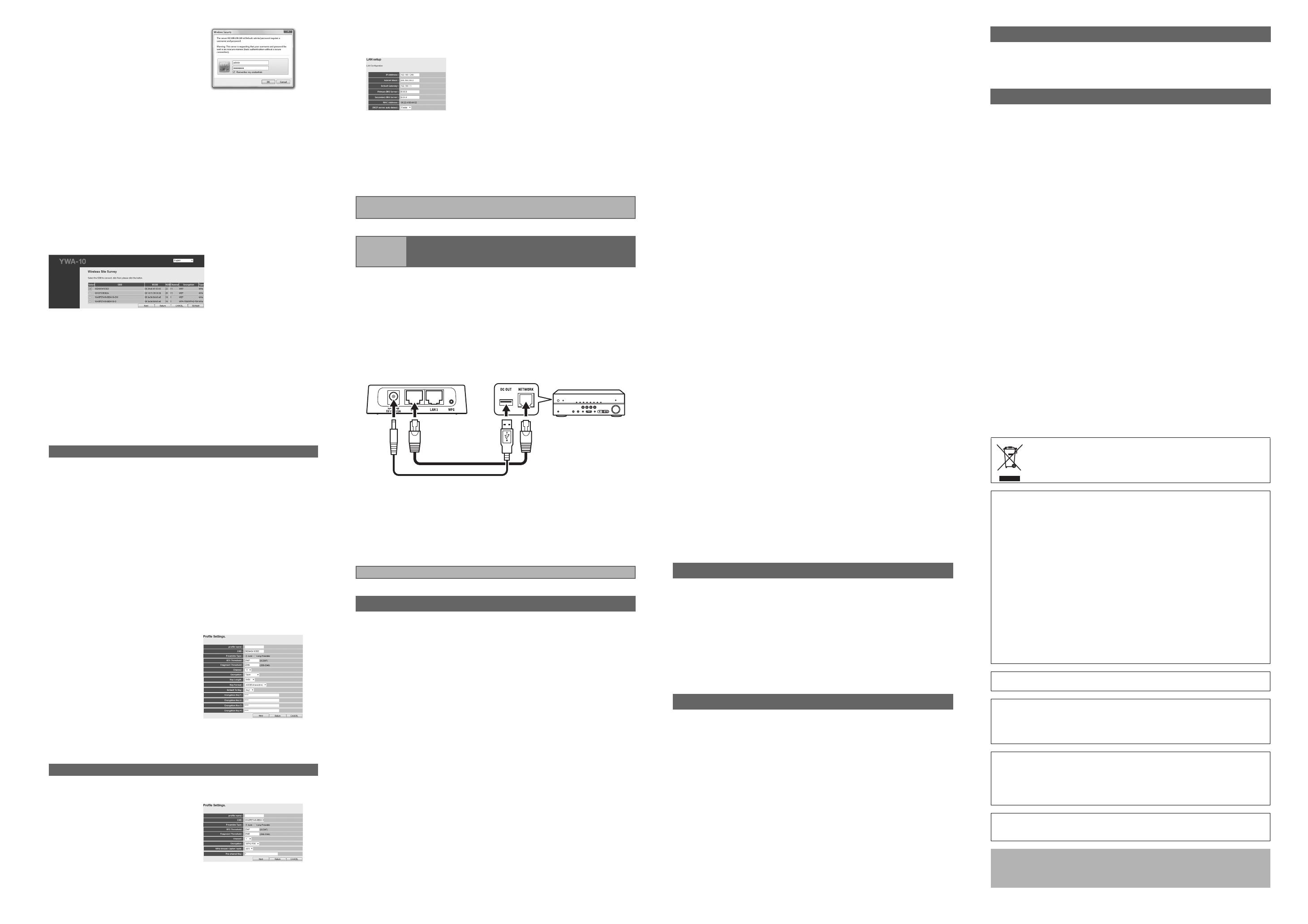
e Click [Setup Wizard] and then [Next], in that order.
The “Wireless Site Survey” screen appears.
f On the “Wireless Site Survey” screen, choose the same SSID as in (1)
on the table in “1 Check the network that you are attempting to connect
to.” and then click [Next].
Notes
• When the SSID does not appear, click [Refresh] and then search again.
• If the SSID (the name of the device you are connecting to) does not
display even when the above operation is performed, the wireless LAN
router (base unit) power is turned off, or the SSID name notification is
turned off (SSID Broadcast refusal).
In such cases, enter the same SSID as the wireless LAN router (base
unit) directly.
• It is recommended that you connect to an SSID with an RSSI (Received
Signal Strength Indication) of 50 or above.
g Follow the procedure in “1 Check the network that you are attempting
to connect to.” to set up this unit.
Refer to “■ When using WEP security settings” in the table on the reverse
page to set up this unit.
a Enter the profile name of your choice in “profile name”.
b When (2) in the table is “Open”
^ Select “Open” under “Encryption”.
When (2) in the table is “Shared”
^ Select “SHARED” under “Encryption”.
c When (5) in the table is set to use a 10 or 5 letter password
^ Select “64Bit” under “Key Length”.
When (5) in the table is set to use a 26 or 13 letter password
^ Select “128Bit” under “Key Length”.
d When (3) in the table is “Hexadecimal”
^ Select “Hex” under “Key Format”.
When (3) in the table is “ASCII”
^ Select “ASCII” under “Key Format”.
e Enter the same encryption key
as in (5) on the table in the
same Encryption key field as in
(4) in the table.
For example, when (4) in the
table is “Key 1”, enter the same
password as “Encryption Key
1” from (5) in the table.
f Select the same default key as
(4) from the table in “Default Tx
Key”.
g Click [APPLY].
Refer to “■ When using WPA/WPA2 security settings” in the table on the
reverse page to set up this unit.
a Enter the profile name of your
choice in “profile name”.
b Enter the same password as in
(4) from the table in the “Pre-
shared Key” field.
c Click [APPLY].
Note
To register multiple base units repeat procedures e through g.
When (2) in the table is “Open / Shared”
When (2) in the table is “WPA-PSK”/“WPA2-PSK”
h The “LAN Setup” screen appears. Change the IP address if it is already
being used by another device.
Check the settings and click [APPLY].
i The seconds before this unit restarts are counted down (30 seconds).
When the count reaches “0”, this unit will restart. Click “OK” and check
that this unit can connect to the access point.
j Close the browser.
k Remove the connected LAN cable and USB power cable.
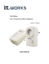
a Use the supplied LAN cable to connect the LAN1 port (or the LAN2 port)
on this unit to the NETWORK port on the AV product. Then, use the
supplied USB power cable to connect the power connector on this unit
to the DC OUT jack on the AV product.
The indicator on the front panel of this unit lights. Wait for approximately one
minute and then carry out the following procedure.
Note
If the AV product is not equipped with a DC OUT jack, connect to the USB
connector on the front panel.
b Turn on the power of the AV product that you wish to connect this unit
to.
c Check that the network functions of the connected AV products
function correctly.
Refer to the owner’s manual of the AV product for information on these
network functions.
■ The power does not turn on
• Check that the USB power cable is firmly connected to this unit and the AV
product.
• Check that the AV Receiver Network Standby is set to ON. (If Network
Standby is OFF, power supply to the DC OUT jack will turn OFF when the AV
Receiver is set to Standby.)
■ Cannot connect using WPS
• Only some devices are WPS compatible. If you are unable to connect using
WPS, configure the settings manually.
■ An error occurs when “ywa.setup” or “192.168.1.249” is input in the
address field of the web browser, or the login screen does not appear.
• Check the IP address settings (automatic or fixed setting) of the PC. If the
PC is set to fixed setting, change it to automatic.
• The IP address of this unit may have changed from its default setting. Refer
to “Resetting this unit” and reset this unit.
• If you are using any security software, turn it off temporarily. Refer to the
owner’s manual of the security software for information on how to turn it off.
• If the wireless channel of the base unit is set to “12” or “13”, change it to a
channel between “1” and “11”. (USA and Canada models only)
■ Cannot log in from the login screen
• The ID and password may have been changed. Refer to “Resetting this unit”
and reset this unit.
This completes connection with the base unit. Proceed to “Step 3
Connecting to an AV product”.
Step 3 Connecting to an AV product
This completes the setup procedure.
Troubleshooting
■ Unable to find the base unit in “Wireless Site Survey” on the setup
screen
• If this unit is too far away from the base unit (wireless LAN router, etc.) or
there is an obstacle between them, try searching again in close proximity to
the base unit, in a location where there are no obstacles between the two
devices.
• The base unit may be set to refuse SSID Broadcast. Set the SSID, security
mode, and key by hand.
■ Unable to configure settings in “Wireless Site Survey” on the setup
screen
• Check the SSID. If the base unit SSID or password contain characters that
this unit cannot use, the password is greater than 30 characters long, or the
SSID is greater than 32 characters long, change them to settings that are
compatible with this unit.
• Check the base unit security mode, and set the same security mode on the
YWA-10 setup screen.
• The password you have entered may be incorrect. Check the password and
re-enter it.
• If multiple base units are registered, select the units to which you wish to
connect, and click [Connect].
■ Not connected to the Internet, or connected to the Internet, but
experiencing sound skipping.
• There may be a problem with your Internet environment. Without using this
unit, check whether your PC can connect to the Internet, as in Step 1.
• Refer to “Step 3 Connecting to an AV product” and check that the products
and cables are connected correctly.
• If this unit is too far away from the base unit (wireless LAN router, etc.) or
there is an obstacle between them, try searching again in close proximity to
the base unit, in a location where there are no obstacles between the two
devices.
• If there is a microwave oven in the immediate area, electromagnetic waves
from the microwave oven may be interfering with the wireless transmissions.
Move further away from the microwave oven and try connecting again.
• The base unit may be restricting connections by MAC Address. Add the MAC
address written on the underside of this unit to the list of permitted
connections on the base unit.
• Turn on the power to this unit again.
• Turn on the power to the base unit (wireless LAN router, etc) again.
• Check the IP address settings (automatic or fixed setting) of the network
device to which this product is to be connected. If the network device is set to
fixed setting, change it to automatic.
• Check that the DHCP server function on the base unit is set to ON.
• Try removing and reinserting the LAN cable connecting this unit and the AV
Receiver.
• Connection is not possible if multiple YWA-10 units are in use, or if another
device is using the IP address “192.168.xxx.249”. Refer to “Changing the IP
address” and change to a unique IP address.
• If you are unable to connect even after performing the above procedure,
reset this unit. Refer to “Resetting this unit” for information on resetting.
• Audio content that utilizes a significant amount of data may not transmit
correctly over a wireless connection in some cases. Use audio formats that
require a small amount of data.
Note
Resetting this unit will erase all of its settings. Be sure to note down the
necessary information before resetting.
a Check that this unit’s power is on.
b Press the Reset button for at least 10 seconds.
c Release the Reset button when all the indicators are blinking.
When this unit restarts after approximately 2 minutes, resetting is complete.
When resetting is complete, set up this unit again, starting from “Step 2-A
Connecting to the base unit (using WPS)” or “Step 2-B Connecting to the base
unit (manual configuration)”.
a Reset this unit.
Refer to “Resetting this unit”.
b Connect this unit to a PC.
Refer to “2 Connect this unit to a PC” in “Step 2-B Connecting to the base
unit (manual configuration)”.
c Open the setting screen of this unit.
Refer to “3 Setting up this unit” in “Step 2-B Connecting to the base unit
(manual configuration)”, and carry out procedures 1-3.
d Click “Network” in the menu in the upper area of the setting screen.
e On the “LAN Setup” screen, enter “192.168.1.xxx” as an IP address.
Set the “xxx” in “192.168.1.xxx” to a number that is between 2 and 248, and
one that is not used by other devices.
f Cli
ck [APPLY].
g Se
t up this unit again.
Carry out “Step 2-A Connecting to the base unit (using WPS),” or “Step 2-B
Connecting to the base unit (manual configuration)”.
Resetting this unit
Changing the IP address
User name (Login ID): admin
IP address: 192.168.1.249
Password: password
Wireless section
Wireless type .................................. IEEE802.11n, IEEE802.11g, IEEE802.11b
Frequency of operation .......................................... US: 1—11 ch, EU: 1—13 ch
Frequency band ................................................ 2.4 GHz (2,400—2,483.5 MHz)
Type of modulation ...................... IEEE802.11n: OFDM, IEEE802.11g: OFDM,
IEEE802.11b: DSSS
Antenna gain...............................................................................................2 dBi
Antenna...................................................................Internal antenna x 2 (2T2R)
Access mode .......................................................................Infrastracture mode
Bandwidth .......................................................................... 20 MHz and 40 MHz
Security ...................WPA2-PSK (TKIP), WPA2-PSK (AES), WPA-PSK (TKIP),
WPA-PSK (AES), SHARED, OPEN (WEP: 64bit/128bit,
Key format: ASCII/Hexadecimal), Disabled (No encryption)
Wired section
Ethernet type......................IEEE802.3u (100Base-Tx), IEEE802.3i (10Base-T)
Interface .......................................................................RJ-45 port x 2 (LAN x 2)
Ethernet cable......................................................................Category 5 or more
Configuration window requirement
OS............................................... Windows 7(32bit/64bit)/Vista(32bit/64bit)/XP,
Mac OS X 10.4/10.5/10.6, CPU: Intel/PowerPC support)
Browser................................ Internet Explorer 6 or above, Firefox 5.0 or above
General
Dissipation power.......................................... Maximum of approximately 2.3 W
Power supply ................................................................................DC +5V 0.5 A
External dimensions.......................... 78 x 70 x 22 (mm) *Excluding protrusions
Weight..........................................................................................................62 g
Operating temperature range.........................................Temperature: 0—40 °C
Humidity: 10—90 % (No condensation)
Strage temperature range..........................................Temperature: –20—60 °C
Humidity: 10—90 % (No condensation)
* Specifications are subject to change without notice.
Factory default settings
Specifications
(E.U. only)
This symbol mark is according to the EU directive 2002/96/EC.This symbol
mark means that electrical and electronic equipment, at their end-of-life, should
be disposed of separately from your household waste. Please act according to
your local rules and do not dispose of your old products with your normal
household waste.
■ Precautions
Read this before using this unit.
To assure the finest performance, please read this manual carefully. Keep it in a safe place
for future reference.
1 Install this unit in a cool, dry, clean place away from direct sunlight, heat sources, and
sources of excessive vibration, dust, moisture, and/or cold. (Do not use/keep this unit in
a car etc.)
2 Locate this unit away from other electrical appliances, motors, or transformers to avoid
humming sounds.
3 Do not expose this unit to sudden temperature changes from cold to hot, and do not
locate this unit in an environment with high humidity (i.e. a room with a humidifier) to
prevent condensation inside this unit, which may cause an electrical shock, fire, damage
to this unit, and/or personal injury.
4 Do not clean this unit with chemical solvents; this might damage the finish. Use a clean,
dry cloth.
5 Do not attempt to modify or fix this unit. Contact qualified Yamaha service personnel
when any service is needed. The cabinet should never be opened for any reason.
6 Be sure to read the “Troubleshooting” section regarding common operating errors before
concluding that the unit is faulty.
7 Before moving this unit, disconnect USB power cable from the AV product.
Do not use this unit within 22 cm (9 inches) of persons with a heart pacemaker implant or
defibrillator implant.
Explanations regarding GPL
This product utilizes GPL/LGPL open-source software in some sections. You have the right
to obtain, duplicate, modify, and redistribute this open-source code only. For information on
GPL/LGPL open source software, how to obtain it, and the GPL/LGPL license, refer to the
Yamaha Corporation website (http://download.yamaha.com/sourcecodes/ywa-10/).
• This product is limited to indoor use only.
• Frequencies used by this product may be prohibited to use in some counties. As a user of
this product, you have responsibilities to use this product only in the intended countries
and confirm that this product is set to use frequencies and channels that are allowed to
use in your country. Violators may be punishable by law of the country. For information
about laws of each country, please refer to “ERC/REC 70-03”.
We, the manufacturer (Yamaha Corporation) hereby declare that this equipment (Wireless
Network Adapter), model YWA-10 is in compliance with the essential requirements and
other relevant provisions of Directive 1999/5/EC.
• Microsoft, Windows 7, Windows Vista and Windows XP are registered trademarks or
trademarks of Microsoft Corporation in the U.S. and other countries.
• Other product names, technology names, and company names mentioned in this manual may
be trademarks or registered trademarks of their respective owners and are hereby
acknowledged.
YWA-10_dtp_En.fm Page 2 Thursday, April 12, 2012 12:07 AM


 IT Works 500MBPS X2 WIFI/2XRJ45 Le manuel du propriétaire