Rane ME60S Manuel utilisateur
- Catégorie
- Équipement musical supplémentaire
- Taper
- Manuel utilisateur

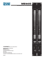
ME60S
microGRAPHIC EQUALIZER
CONTENTS (in order of appearance)
Important Safety Instructions
ME60S Manual
ME60S Data Sheet
Sound System Interconnection
Warranty
Declaration of Conformity
Schematics are downloadable at www.rane.com/me60s.html
22347
10
40
15
150
30k
40k
10k
5k
250 3k
10
40
15
150
30k
40k
10k
5k
250 3k
0
6
•
3
•
•
•
3
6
0
6
•
3
•
•
•
3
6
±6
±6
10
0
2
4
8
6
10
0
2
4
8
6
ME60S
MICROGRAPHIC
EQUALIZER
CHANNEL 2
CHANNEL 1
HIGH
LOW
HIGH
LOW
CUT FILTERS
CUT FILTERS
400
31.5
25
40
63
50
100
80
160
125
250
200
315
12.5k
1k
630
500
800
1.6k
1.25k
2k
3.15k
2.5k
5k
4k
8k
6.3k
10k
20k
16k
400
31.5
25
40
63
50
100
80
160
125
250
200
315
12.5k
1k
630
500
800
1.6k
1.25k
2k
3.15k
2.5k
5k
4k
8k
6.3k
10k
20k
16k
OL
LEVEL
RANGE
BYPASS
OL
LEVEL
RANGE
BYPASS
±12
±12
0
12
•
6
•
•
•
6
12
0
12
•
6
•
•
•
6
12
POWER

ATTENTION: RISQUE DE CHOCS ELECTRIQUE - NE PAS OUVRIR
RISK OF ELECTRIC SHOCK
DO NOT OPEN
CAUTION
To reduce the risk of electrical shock, do not open the unit. No user
serviceable parts inside. Refer servicing to qualied service personnel.
e symbols shown below are internationally accepted symbols
that warn of potential hazards with electrical products.
is symbol indicates that a dangerous voltage
constituting a risk of electric shock is present
within this unit.
is symbol indicates that there are important
operating and maintenance instructions in the
literature accompanying this unit.
WARNING
IMPORTANT SAFETY INSTRUCTIONS
1. Read these instructions.
2. Keep these instructions.
3. Heed all warnings.
4. Follow all instructions.
5. Do not use this apparatus near water.
6. Clean only with a dry cloth.
7. Do not block any ventilation openings. Install in accordance with manufacturer’s instructions.
8. Do not install near any heat sources such as radiators, registers, stoves, or other apparatus (including ampliers) that produce heat.
9. Do not defeat the safety purpose of the polarized or grounding-type plug. A polarized plug has two blades with one wider than the other. A
grounding-type plug has two blades and a third grounding prong. e wide blade or third prong is provided for your safety. If the provided plug
does not t into your outlet, consult an electrician for replacement of the obsolete outlet.
10. Protect the power cord and plug from being walked on or pinched particularly at plugs, convenience receptacles, and the point where it exits from
the apparatus.
11. Only use attachments and accessories specied by Rane.
12. Use only with the cart, stand, tripod, bracket, or table specied by the manufacturer, or sold with the apparatus. When a cart is used, use caution
when moving the cart/apparatus combination to avoid injury from tip-over.
13. Unplug this apparatus during lightning storms or when unused for long periods of time.
14. Refer all servicing to qualied service personnel. Servicing is required when the apparatus has been damaged in any way, such as power supply
cord or plug is damaged, liquid has been spilled or objects have fallen into the apparatus, the apparatus has been exposed to rain or moisture, does
not operate normally, or has been dropped.
15. e plug on the power cord is the AC mains disconnect device and must remain readily operable. To completely disconnect this apparatus from
the AC mains, disconnect the power supply cord plug from the AC receptacle.
16. is apparatus shall be connected to a mains socket outlet with a protective earthing connection.
17. When permanently connected, an all-pole mains switch with a contact separation of at least 3 mm in each pole shall be incorporated in the
electrical installation of the building.
18. If rackmounting, provide adequate ventilation. Equipment may be located above or below this apparatus, but some equipment (like large power
ampliers) may cause an unacceptable amount of hum or may generate too much heat and degrade the performance of this apparatus.
19. is apparatus may be installed in an industry standard equipment rack. Use screws through all mounting holes to provide the best support.
WARNING: To reduce the risk of re or electric shock, do not expose this apparatus to rain or moisture. Apparatus shall not be exposed to dripping
or splashing and no objects lled with liquids, such as vases, shall be placed on the apparatus.
NOTE: is equipment has been tested and found to comply with the limits for a Class B digital device, pursuant to part 15 of the FCC Rules.
ese limits are designed to provide reasonable protection against harmful interference in a residential installation. is equipment generates, uses
and can radiate radio frequency energy and, if not installed and used in accordance with the instructions, may cause harmful interference to radio
communications. However, there is no guarantee that interference will not occur in a particular installation. If this equipment does cause harmful
interference to radio or television reception, which can be determined by turning the equipment o and on, the user is encouraged to try to correct
the interference by one or more of the following measures:
• Reorient or relocate the receiving antenna.
• Increase the separation between the equipment and receiver.
• Connect the equipment into an outlet on a circuit dierent from that to which the receiver is connected.
• Consult the dealer or an experienced radio/TV technician for help.
CAUTION: Changes or modications not expressly approved by Rane Corporation could void the user's authority to operate the equipment.
CAN ICES-3 (B)/NMB-3(B)
WARNING: is product may contain chemicals known to the State of California to cause cancer, or birth defects or other reproductive harm.

ATTENTION: RISQUE DE CHOCS ELECTRIQUE - NE PAS OUVRIR
RISK OF ELECTRIC SHOCK
DO NOT OPEN
CAUTION
An d’éviter tout risque de choc électrique, ne pas ouvrir l’appareil.
Aucune pièce ne peut être changée par l’utilisateur. Contactez un
SAV qualié pour toute intervention.
Les symboles ci-dessous sont reconnus internationalement
comme prévenant tout risque électrique.
Ce symbole indique que cette unité utilise un
voltage élevé constituant un risque de choc
électrique.
Ce symbole indique la présence d’instructions
d’utilisation et de maintenance importantes dans le
document fourni.
ATTENTION
INSTRUCTIONS DE SÉCURITÉ
1. Lisez ces instructions.
2. Gardez précieusement ces instructions.
3. Respectez les avertissements.
4. Suivez toutes les instructions.
5. Ne pas utiliser près d’une source d’eau.
6. Ne nettoyer qu’avec un chion doux.
7. N’obstruer aucune évacuation d’air. Eectuez l’installation en suivant les instructions du fabricant.
8. Ne pas disposer près d’une source de chaleur, c-à-d tout appareil produisant de la chaleur sans exception.
9. Ne pas modier le cordon d’alimentation. Un cordon polarisé possède 2 lames, l’une plus large que l’autre. Un cordon avec tresse de masse possède
2 lames plus une 3è pour la terre. La lame large ou la tresse de masse assurent votre sécurité. Si le cordon fourni ne correspond pas à votre prise,
contactez votre électricien.
10. Faites en sorte que le cordon ne soit pas piétiné, ni au niveau du l, ni au niveau de ses broches, ni au niveau des connecteurs de vos appareils.
11. N’utilisez que des accessoires recommandés par Rane.
12. N’utilisez que les éléments de transport, stands, pieds ou tables spéciés par le fabricant ou vendu avec l’appareil. Quand vous utlisez une valise de
transport, prenez soin de vous déplacer avec cet équipement avec prudence an d’éviter tout risque de blessure.
13. Débranchez cet appareil pendant un orage ou si vous ne l’utilisez pas pendant un certain temps.
14. Adressez-vous à du personnel qualié pour tout service après vente. Celui-ci est nécessaire dans n’importe quel cas où l’appareil est abimé : si le
cordon ou les ches sont endommagés, si du liquide a été renversé ou si des objets sont tombés sur l’appareil, si celui-ci a été exposé à la pluie ou
l’humidité, s’il ne fonctionne pas correctement ou est tombé.
15. La che du cordon d’alimentation sert à brancher le courant alternatif AC et doit absolument rester accessible. Pour déconnecter totalement
l’appareil du secteur, débranchez le câble d’alimentation de la prise secteur.
16. Cet appareil doit être branché à une prise terre avec protection.
17. Quand il est branché de manière permanente, un disjoncteur tripolaire normalisé doit être incorporé dans l’installation électrique de l’immeuble.
18. En cas de montage en rack, laissez un espace susant pour la ventilation. Vous pouvez disposer d’autres appareils au-dessus ou en-dessous de celui-
ci, mais certains (tels que de gros amplicateurs) peuvent provoquer un buzz ou générer trop de chaleur au risque d’endommager votre appareil et
dégrader ses performances.
19. Cet appareil peut-être installé dans une baie standard ou un chassis normalisé pour un montage en rack. Visser chaque trou de chaque oreille de
rack pour une meilleure xation et sécurité.
ATTENTION: an d’éviter tout risque de feu ou de choc électrique, gardez cet appareil éloigné de toute source d’humidité et d’éclaboussures quelles
qu’elles soient. L’appareil doit également être éloigné de tout objet possédant du liquide (boisson en bouteilles, vases,…).
REMARQUE: Cet équipement a été testé et approuvé conforme aux limites pour un appareil numérique de classe B, conformément au chapitre 15
des règles de la FCC. Ces limites sont établis pour fournir une protection raisonnable contre tout risque d’interférences et peuvent provoquer une
énergie de radiofréquence s'il n'est pas installé et utilisé conformément aux instructions, peut également provoquer des interférences aux niveaux
des équipements de communication. Cependant, il n'existe aucune garantie que de telles interférences ne se produiront pas dans une installation
particulière. Si cet équipement provoque des interférences en réception radio ou télévision, ceci peut être detecté en mettant l'équipement sous/hors
tension, l'utilisateur est encouragé à essayer de corriger cette interférence par une ou plusieurs des mesures suivantes:
• Réorienter ou déplacer l'antenne de réception.
• Augmenter la distance entre l'équipement et le récepteur.
• Connecter l'équipement à une sortie sur un circuit diérent de celui sur lequel le récepteur est branché.
• Consulter un revendeur ou un technicien radio / TV expérimenté.
ATTENTION: Les changements ou modications non expressément approuvés par Rane Corporation peuvent annuler l'autorité de l'utilisateur à
manipuler cet équipement et rendre ainsi nulles toutes les conditions de garantie.
CAN ICES-3 (B)/NMB-3(B)
Cartons et papier à recycler.

Manual-1
OPERATORS MANUAL ME60S
microGRAPHIC EQUALIZER
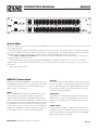
ME60S Connection
When rst connecting the ME60S to other components, leave
the POWER switch o until the very last. is gives you a chance
to make mistakes and correct them without damaging your
fragile speakers, ears and nerves.
INPUTS
e ¼" and XLR Inputs are wired in parallel and are actively
balanced. Each works equally well. Choose strictly from a
required hardware point-of-view. e XLR wiring convention
adheres to American, British and International standards of pin
2 or tip being hot, pin 3 or ring being return, and pin 1 or sleeve
being shield. It is not necessary to short any inputs to ground—
it doesn’t hurt, it’s just not necessary. Use pin 1, or the shell, for
shield ground. Unbalanced operation involves using only pin 2
or tip as signal, and pin 1 or sleeve as shield and ground.
OUTPUTS
e Outputs mimic the Inputs. Balanced output requires using
pin 2 or tip, and pin 3 or ring for the signal. It does not require
pin 1 or shield. e signal exists dierentially between the two
balanced leads; ground is not involved. For hum-free systems
ground is used only for shielding.
EXPANDING
Expanding and/or daisychaining the Inputs and Outputs nor-
mally uses the ¼" jacks. Two parallel Input connectors allows
driving a second signal processor or amplier without special
cabling.
SIGNAL LEVELS
Signal levels from -10 dBV to +4 dBu are considered normal
and within range (at least 20 dB of headroom exists above these
levels). Do not directly connect microphones into the ME60S.
ese require a separate mic preamp.
Quick Start
Okay, know-it-all. So you don’t need to read the manual. Well do your mother a favor and just read this section and you don’t have to
read anything else. Ever.
Hook-up is intuitive. Just follow the silkscreened instructions on the rear of the unit. All three Inputs are wired in parallel (they
do not sum); and all three Outputs are wired in parallel. Use any one Input and any or all Outputs. Polarity convention is per IEC/
ANSI/AES standards of pin 2 positive, pin 3 negative and pin 1 shield. e ME60S does not invert the signal.
Set the LOW and HIGH CUT FILTER controls as necessary to restrict bandwidth. Full frequency response results from posi-
tioning them all the way to the bottom.
Anyone familiar with other graphic equalizers nds the ME60S just as familiar. Setting curves is as easy as it is on all Rane
graphics thanks to our innovative constant-Q circuitry. If you feel you want more information on setting up your curves, please see
the back page.
ere, now was that so bad?
WEAR PARTS is product contains no wear parts.
10
40
15
150
30k
40k
10k
5k
250 3k
10
40
15
150
30k
40k
10k
5k
250 3k
0
6
•
3
•
•
•
3
6
0
6
•
3
•
•
•
3
6
±6
±6
10
0
2
4
8
6
10
0
2
4
8
6
ME60S
MICROGRAPHIC
EQUALIZER
CHANNEL 2
CHANNEL 1
HIGH
LOW
HIGH
LOW
CUT FILTERS
CUT FILTERS
400
31.5
25
40
63
50
100
80
160
125
250
200
315
12.5k
1k
630
500
800
1.6k
1.25k
2k
3.15k
2.5k
5k
4k
8k
6.3k
10k
20k
16k
400
31.5
25
40
63
50
100
80
160
125
250
200
315
12.5k
1k
630
500
800
1.6k
1.25k
2k
3.15k
2.5k
5k
4k
8k
6.3k
10k
20k
16k
OL
LEVEL
RANGE
BYPASS
OL
LEVEL
RANGE
BYPASS
±12
±12
0
12
•
6
•
•
•
6
12
0
12
•
6
•
•
•
6
12
POWER

Manual-2
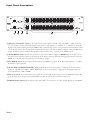
Front Panel Description
1 Channels 1 and 2 LEVEL controls set the overall desired gain through the unit. e range is from O to +8 dB for balanced
use, or from O to +2 dB with unbalanced inputs. Unity gain is at approximately “6” (balanced) or “7” (unbalanced). Using the
highest setting (without lighting the Overload (OL) indicator) yields the best signal-to-noise performance. e OL indicator moni-
tors all critical points for excessive signal levels. It lights whenever these levels exceed 3 dB below clipping. Occasional ickering is
normal; however, if it glows steadily, reduce the signal coming from the source, or turn down the LEVEL control.
2 Channel BYPASS switches activates the “hard-wire” bypass function. When engaged (red BYPASS LED on), all three pins of
the input connectors directly connect to the same pins on the output connectors (hard-wired). Engaging this switch converts the
ME60S into a relatively expensive patch cord, but one with pretty lights.
3 Filter RANGE switch: e gain range of the lter sliders is switchable (as a group) from ±6 dB for high resolution, to ±12 dB for
maximum boost/cut capability.
4 Channel LOW and HIGH CUT FILTER controls. LOW CUT sets the corner frequency (-3 dB point) for the low cut lter
(high pass), adjustable from 10 Hz to 250 Hz. HIGH CUT sets the corner frequency (-3 dB point) for the high cut lter (low
pass), adjustable from 3 kHz to 40 kHz.
5 Filter level controls set the individual levels for each of the constant-Q lters. eir range is set by the RANGE switch 3. e
grounded center-detent design ensures individual lters are o and bypassed when positioned to their centers.
6 POWER switch & indicator glows yellow any time this switch is closed and power is, in fact, actually owing into the ME60S.
10
40
15
150
30k
40k
10k
5k
250 3k
10
40
15
150
30k
40k
10k
5k
250 3k
0
6
•
3
•
•
•
3
6
0
6
•
3
•
•
•
3
6
±6
±6
10
0
2
4
8
6
10
0
2
4
8
6
ME60S
MICROGRAPHIC
EQUALIZER
CHANNEL 2
CHANNEL 1
HIGH
LOW
HIGH
LOW
CUT FILTERS
CUT FILTERS
400
31.5
25
40
63
50
100
80
160
125
250
200
315
12.5k
1k
630
500
800
1.6k
1.25k
2k
3.15k
2.5k
5k
4k
8k
6.3k
10k
20k
16k
400
31.5
25
40
63
50
100
80
160
125
250
200
315
12.5k
1k
630
500
800
1.6k
1.25k
2k
3.15k
2.5k
5k
4k
8k
6.3k
10k
20k
16k
OL
LEVEL
RANGE
BYPASS
OL
LEVEL
RANGE
BYPASS
±12
±12
0
12
•
6
•
•
•
6
12
0
12
•
6
•
•
•
6
12
POWER
1 2 3 4 65

Manual-3
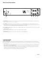
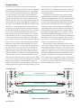
Rear Panel Description
1 XLR INPUT connector. Pin 2 is positive, pin 3 is negative and pin 1 is shield. For unbalanced operation, use pin 2 as hot and
pin 1 as return. It is not necessary to connect pin 3.
2 ¼" INPUT connector. is ¼" tip-ring-sleeve (TRS) connector parallels the XLR connector described below. Tip is positive,
ring is negative and sleeve is shield. Tip-sleeve (TS) cables will often work if the cables are short (under 10 feet [3 meters]). See the
Sound System Interconnection RaneNote included with this manual for correct wiring.
3 ¼" OUTPUT connector. is ¼" TRS connector parallels the XLR connector described below. As before, tip is hot, ring is cold
and sleeve is shield.
4 XLR OUTPUT connector. Pin 2 is positive, pin 3 is negative and pin 1 is shield.
5 POWER IEC jack connects anywhere in the world to AC line voltage, 100-240 VAC.
Important Note
CHASSIS GROUNDING
If after hooking up your system it exhibits excessive hum or buzzing, there is an incompatibility in the grounding conguration
between units somewhere. Your mission, should you accept it, is to discover how your particular system wants to be grounded. Here
are some things to try:
1. If your equipment is in a rack, verify that all chassis are tied to a good earth ground, either through the line cord grounding pin or
the rack screws to another grounded chassis.
2. Units with outboard power supplies do NOT ground the chassis through their line cords. Make sure these units are grounded
either to another chassis which is earth grounded, or directly to the grounding screw on an AC outlet cover by means of a wire
connected to a screw on the chassis with a star washer to guarantee proper contact.
3. See the Sound System Interconnection RaneNote included with this manual.
OUTPUT
INPUT
OUTPUT
INPUT
CHANNEL 1
CHANNEL 2
100-240 V
50/60 Hz 12 WATTS
COMMERCIAL AUDIO
EQUIPMENT 24TJ
R
WIRING
Tip / Pin 2 = Positive (+)
Ring / Pin 3 = Negative (–)
Sleeve = Signal Ground
Pin 1 = Chassis Ground
All audio jacks are Class 2 wiring.
ME60S
RANE CORPORATION
12345

Manual-4
©Rane Corporation 10802 47th Ave. W., Mukilteo WA 98275-5000 TEL 425-355-6000 FAX 425-347-7757 WEB rane.com
Operating Instructions
Insuring the proper level of gain though the ME60S is just as
important as adjusting the equalizer bands. Improper gain dis-
tribution is a common cause of loss of system headroom and less
than optimum noise performance.
e OverLoad LED informs of an imminent or passed
overload to the equalizer. Occasional blinking of the OL with
program source material is ne, indicating optimized signal to
noise performance of the ME60S. Run the ME60S with an in-
put signal that is as hot as possible without the OL lighting more
than occasionally.
e BYPASS switch allows comparison of equalized versus
un-equalized signal. It is also useful in adjusting the level of the
ME60S for unity gain or best signal-to-noise performance. e
gain of the ME60S is optimized and at unity when there is no
sound level dierence between the bypassed and the active posi-
tions.
e overall gain range of the LEVEL control for the ME60S
is o to +2 dB for unbalanced operation, or o to +8 dB for bal-
anced operation. e level dierence between the equalizer in
Bypass or active can be signicant. Adjust the LEVEL control so
the signal level is the same between the bypassed and active posi-
tions of the BYPASS switch.
GETTING STARTED
Here is one method of setting your equalizer that works well.
Begin with the following settings:
1. Engage the BY PASS switch. (switch depressed, BYPASS LED
on.)
2. Put all sliders in their center position (0 dB). e center posi-
tion has a grounded detent.
3. Position the CHANNEL LEVEL controls about “7” for un-
balanced operation and “6” for balanced operation.
4. Set LOW and HIGH CUT lters fully down, corresponding
to 10 Hz and 40 kHz.
5. Apply a signal to the system.
6. Verify the OL LED is not on—occasionally blinking during
extreme peaks indicates an optimal setting. But if it lights up
a lot or lights steadily, lower the output level of the previous
device in the signal chain.
7. Release the BYPASS switch and begin adjusting the equalizer
lters.
8. During lter band adjustments, if the OL LED lights more
than occasionally, turn down the output of the previous de-
vice in the signal chain.
9. Once all lter bands are adjusted to your liking, compare the
signal loudness with the equalizer bypassed and active. Adjust
the LEVEL controls on the ME60S so there is no dierence
between the levels of bypassed versus active.
10. e last step is to reconrm that the OL LED lights only
when there are large signal spikes in the program material, as
in step 6 above.
For insight into how to use an equalizer, to alleviate acoustic
problems or to adjust the overall tone of the program material,
please read the next two sections.
ACOUSTIC COMPENSATION
A graphic equalizer may be used to correct many acoustic
problems. However, one should fully understand the ramica-
tions of doing so. Acoustic problems are generally not consistent
across the entire area of sound coverage. is is much more of a
problem when setting up a sound system for large venues. In a
typical large room or hall, there will be areas that have acoustic
reinforcement problems and other areas where certain frequen-
cies are almost entirely canceled out. Try to seek an acoustic
remedy for acoustic problems whenever possible. When this is
not possible or feasible, an equalizer may be used to compensate
for an acoustic problem. But the problem is only improved at
the point where the measurement is taken; other locations in the
room may be adversely aected by the equalizer setting. For this
reason, measure the acoustic response of the system from several
locations and average the equalizer’s setting. Doing this helps
most locations in the venue to have an equal sound quality.
e best way to “see” what the acoustic signature of the room
is doing to sound is to use a real time analyzer or any of the
many computerized measurement systems. Using these devices
to analyze the response of the room and the sound system is the
only accurate means available for setting an equalizer properly.
Equalization can be like spice in the hands of a master chef.
A little goes a long way in improving sound quality, too much
and the mix is spoiled. If modest amounts of equalization (6-8
dB) do not solve the problem, it is best remedied by other means.
Avoid adding large amounts of boost below 63 Hz, especially
when using vented bass cabinets. Boosting frequencies below
the vented enclosure’s low frequency cuto can easily cause over
excursion of the speaker’s cone, causing premature failure. In ad-
dition, boosting low frequencies can make your power amplier
run hotter, leading to premature amplier failure.
When equalizer adjustment is completed, compare the un-
equalized sound with the equalized sound by alternately engag-
ing the BYPASS switch. Use familiar source material and walk
around in the sound coverage area to insure that no anomalies
have been introduced into the sound system. If it sounds good,
you’re done.
TONE CONTOURING
If a ME60S is used for tone contouring by ear, be careful about
adding upper bass (63 Hz to 200 Hz) as this can cause “muddi-
ness” or loss of clear denition. (Also see the previous warning
about boosting frequencies below 63 Hz.) Middle frequency
problems usually express themselves by vocals having a nasal
quality (too much mid band boost) or vocals not being eas-
ily understandable (usually caused by mid band frequencies
being under represented in the overall sound). High frequency
problems show as “sizzle”— not good, and is sometimes caused
by too much high frequency boosting. is is most obvious
with cymbals and hi-hats. To use the cooking metaphor, high
frequencies should simmer, not sizzle.

ME60S
microGRAPHIC EQUALIZER
Data Sheet-1
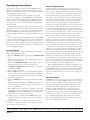
General Description
e Rane ME60S Stereo Constant-Q Equalizer is a two-
channel, ⅓-octave design, housed in a two rack-space unit. It
features a Range switch for high slider resolution in the ±6 dB
mode, equivalent resolution to 45 mm sliders found on larger
models. e ±12 dB mode provides a wide range of control over
system audio.
e ME60S evolved by combining two ME 30 equalizers
in one unit and then embellishing with two adjustable band-
limiting lters on the low and high end. ough consuming only
12 watts of power, a Power switch is added to the ME60S (the
ME 30S consumes 7 watts and does not have a Power switch).
e active lter sections feature Rane’s innovative constant-Q
(constant bandwidth) design. Constant-Q means the bandwidth
of each individual lter is guaranteed to be narrow enough to
prevent unwarranted interaction between lters, yet wide enough
to produce exactly the type of correction curve demanded
by even the most unusual acoustic surroundings. is diers
dramatically from conventional designs of the past, encumbered
with the unfortunate characteristic of changing bandwidth when
changing boost/cut amounts.
e adjustable lters are useful to band limit the audio
signal. For instance, restricting high frequencies to match the
incoming signal usually produces the most quiet system. And
a common use for the Low Cut Filter is limiting the signal go-
ing to 70-volt speaker systems. Often low frequencies saturate
the loudspeaker transformers. Restricting these signals greatly
improves system intelligibility. Full bandwidth use requires posi-
tioning both sliders to their lower limits. is eectively removes
the lters and guarantees 20-20 kHz ±0.5 dB performance.
Front panel controls and indicators include an overall rotary
Level control for each channel as well as Overload indicators.
Passive pushbutton Bypass switches feature LED indicators,
avoiding ambiguity by being on when the unit is Bypassed. (A
passive Bypass switch requires no power to operate. is allows
completion of the audio path should power fail in the ME60S.)
Inputs and Outputs are electronically balanced designs,
capable of unbalanced operation when required. ey accept
and drive all possible signal levels into normal load impedances.
Balanced applications choose between the XLR or ¼" Tip-
Ring-Sleeve connectors. Unbalanced sources also may tie to the
ME60S through mono ¼" connectors (no ring connection).
DATA SHEET
Features
• Constant-Q Bandwidth Design
• Overall Level Controls
• 20 mm Filter Slide Controls
• ±6 dB or ±12 dB Slider Range
• Sweepable Low & High Cut Filters
• Passive Bypass Switches
• Grounded Center Detents at 0 dB
• Infrasonic, Ultrasonic, & RFI Filters
• Fully Balanced XLR Inputs and Outputs
• ¼" TRS Balanced/Unbalanced Inputs and Outputs
• Universal internal switching power supply (100-240 VAC)

ME60S
microGRAPHIC EQUALIZER
Data Sheet-2
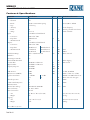
Features & Specifications
Parameter Specication Limit Units Conditions/Comments
Equalizer:
..........Channels Two
..........Bands (2x30) ⅓-Octave ISO Spacing From 25 Hz to 20 kHz
..........Type Constant-Q
..........Accuracy 3 % Center frequency
..........Travel 20 mm Positive grounded center detent
..........Range ±12 or ±6 1 dB Switch selectable
Inputs: Active Balanced/Unbalanced
..........Connectors XLR and ¼" TRS
..........Impedance >20k Balanced 1%
..........Maximum Level +21 1 dBu
Outputs: Active Balanced/Unbalanced
..........Connectors XLR and ¼" TRS
..........Impedance 400 Balanced 200 Unbalanced 1%
..........Maximum Level +21 Balanced +15 Unbalanced 1 dBu 2 k
+19 Balanced +13 Unbalanced 1 dBu 600
Overall Gain Range O to +8 (Balanced Out) min dB Sliders centered
RFI Filters Yes
Passive Bypass Switches Yes
Overload LED reshold 4 1 dB Below clipping
Low Cut Filter 10-250 Hz, 12 dB/octave 3% Hz Butterworth
High Cut Filter 3k-40 kHz, 12 dB/octave 3% Hz
Frequency Response 20-20 kHz ±0.5 dB
10-40 kHz +0/-3 dB
THD & Noise 0.008 .002 % +4 dBu, 20-20 kHz
IM Distortion (SMPTE) 0.005 .003 % 60 Hz / 7 kHz, 4:1, +4 dBu
Signal-to-Noise Ratio re +20 dBu re +4 dBu 20 kHz noise BW; balanced out
112 96 2 dB Sliders centered, unity gain
Channel Separation 75 3 dB 1 kHz
Common Mode Rejection 46 1 dB 1 kHz
Maximum Power 12 W
Universal Line Voltage 100-240 VAC, 50/60 Hz VAC 12W
Unit: Conformity CE, FCC, UL
Unit: Construction All Steel
..........Size 3.5" H x 19" W x 8.5" D (2U) (8.9 cm x 48.3 cm x 21.6 cm)
..........Weight 9 lb (4.1 kg)
Shipping:
..........Size 4.25" x 20.3" x 13.75" (10.8 cm x 52 cm x 35 cm)
..........Weight 12 lb (5.0 kg)
Note: 0 dBu=0.775 Vrms

ME60S
microGRAPHIC EQUALIZER
Data Sheet-3
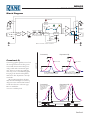
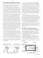
Constant-Q
Constant-Q graphic equalizers arose from
the sound professional’s need for greater
control with less interaction than previ-
ously possible with conventional equal-
izers. You use a constant-Q graphic the
same way you use a conventional graphic.
You just get the desired results quicker,
with far less after adjustment to the adja-
cent sliders.
e accompanying gures dramati-
cally show the advantages of constant-Q
designs. For more technical information,
consult the references on the next page.
Most are available at
www.rane.com/library.html.
Block Diagram
BYPASS
SWITCH
BYPASS
AMPLIFIER
BOOST
TO FILTERS
Channel 1 is shown, channel 2 is identical.
25 Hz
BP
CUT
AMPLIFIER
(3k-40k Hz)
HIGH CUT
FILTER
LEVEL
0 dB
RFI
FILTER
CHANNEL 1
INPUTS
CHANNEL1
OUTPUTS
–6 dB –12 dB +12 dB+6 dB
RANGE
SENSE
OL
OVERLOAD
(+)
(–)
3
2
1
(+)
(–)
–
+
3
2
1
(10-250 Hz)
LOW CUT
FILTER
Constant-Q: Proportional Q:
3dB
1/3 octave 1/3 octave
3dB
3dB
1/3+ octave
3dB
2+ octaves
Bandwidth, dened 3dB down
from peak, remains constant. dramatically with changes in gain.
Bandwidth here changes
FREQUENCY
AMPLITUDE
FREQUENCY
AMPLITUDE
Proportional Q:Constant-Q:
0dB
+3dB
+6dB
1
2
2
1
11
2
2
This design has little
interaction as a
single slider is
moved from
1 to 2. 1 to 2.
moved from
single slider is
aected when a
Both lters are

ME60S
microGRAPHIC EQUALIZER
Data Sheet-4
All features & specications subject to change without notice. 1-2015
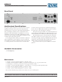
Rear Panel
provide a passive bypass feature for each channel requiring no
power to operate. LED indicators shall be provided to indicate
boost/cut range, overload and bypass conditions.
e inputs and outputs shall be active balanced/unbalanced
designs terminated with XLR and ¼" TRS (tip-ring-sleeve) con-
nectors. RFI, infrasonic and ultrasonic lters shall be provided.
e unit shall incorporate a front panel power switch. e
unit shall be capable of operation by means of its own built-in
universal power supply operating at 100-240 VAC and meet CE
requirements. e unit shall be UL and cUL listed. e unit
shall be entirely constructed from cold-rolled steel.
e unit shall be a Rane Corporation ME60S microGraphic
Equalizer.
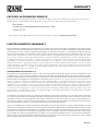
Architectural Specifications
e graphic equalizer shall be a two channel model of constant-
Q design to minimize interactions between adjacent bands,
and shall occupy two rack spaces (2U). Each channel shall have
thirty (30) frequency bands located on standard ISO center
frequencies. Each band shall have a bandwidth of ⅓-octave. A
switchable boost/cut range of 12 dB or 6 dB shall be provided.
A detented and positively grounded 0 dB point shall be provided
on 20 mm linear sliders with dust dams.
Low and high cut lters shall be provided with 12 dB/octave
slopes and adjustable corner frequencies. A rotary overall level
control shall be provided for each channel with a range from o
to +8 dB of gain when used in balanced mode. e unit shall
©Rane Corporation 10802 47th Ave. W., Mukilteo WA 98275-5000 USA TEL 425-355-6000 FAX 425-347-7757 WEB rane.com
References
1. D. Bohn, “Constant-Q Graphic Equalizers,” RaneNote, (1982).
2. D. Bohn, “A New Generation of Filters,” Sound and Video Contractor, vol. 2, pp. 36-39 (Feb. 1984).
3. T. Pennington, “Constant-Q,” Studio Sound, vol.27, pp. 82-85 (Oct. 1985).
4. D. Bohn, “Constant-Q Graphic Equalizers,” J. Audio Eng. Soc., vol. 34, pp. 611-626 (September 1986).
5. D. Bohn, “Exposing Equalizer Mythology,” RaneNote, (1986).
6. D. Bohn, “Operater Adjustable Equalizers,” RaneNote, (1990).
Most of these documents may be found at our website, www.rane.com/library.html
Available Accessories
• SC 3.5 Security Cover

Interconnection-1
Introduction
is note, originally written in 1985, continues to be
one of our most useful references. It’s popularity stems
from the continual and perpetual difficulty of hooking
up audio equipment without suffering through all sorts
of bizarre noises, hums, buzzes, whistles, etc.— not to
mention the extreme financial, physical and psycholog-
ical price. As technology progresses it is inevitable that
electronic equipment and its wiring should be subject
to constant improvement. Many things have improved
in the audio industry since 1985, but unfortunately
wiring isn’t one of them. However, finally the Audio
Engineering Society (AES) has issued a standards
document for interconnection of pro audio equip-
ment. It is AES48, titled “AES48-2005: AES standard
on interconnections —Grounding and EMC practices
— Shields of connectors in audio equipment containing
active circuitry.”
Rane’s policy is to accommodate rather than dic-
tate. However, this document contains suggestions for
external wiring changes that should ideally only be
implemented by trained technical personnel. Safety
regulations require that all original grounding means
provided from the factory be left intact for safe op-
eration. No guarantee of responsibility for incidental
or consequential damages can be provided. (In other
words, don’t modify cables, or try your own version of
grounding unless you really understand exactly what
type of output and input you have to connect.)
Rane Technical Staff
RaneNote 110
© 1985, 1995, 2006, 2007, 2011 Rane Corporation
Sound System
Interconnection
• Cause & prevention of ground loops
• Interfacing balanced & unbalanced
• Proper pin connections and wiring
• Chassis ground vs. signal ground
• Ground lift switches
RaneNote
SOUND SYSTEM INTERCONNECTION

Interconnection-2
Ground Loops
Almost all cases of noise can be traced directly to
ground loops, grounding or lack thereof. It is important
to understand the mechanism that causes grounding
noise in order to effectively eliminate it. Each compo-
nent of a sound system produces its own ground in-
ternally. is ground is usually called the audio signal
ground. Connecting devices together with the inter-
connecting cables can tie the signal grounds of the two
units together in one place through the conductors in
the cable. Ground loops occur when the grounds of the
two units are also tied together in another place: via
the third wire in the line cord, by tying the metal chas-
sis together through the rack rails, etc. ese situations
create a circuit through which current may flow in a
closed “loop” from one unit’s ground out to a second
unit and back to the first. It is not simply the presence
of this current that creates the hum—it is when this
current flows through a unit’s audio signal ground that
creates the hum. In fact, even without a ground loop, a
little noise current always flows through every inter-
connecting cable (i.e., it is impossible to eliminate these
currents entirely). e mere presence of this ground
loop current is no cause for alarm if your system uses
properly implemented and completely balanced inter-
connects, which are excellent at rejecting ground loop
and other noise currents. Balanced interconnect was
developed to be immune to these noise currents, which
can never be entirely eliminated. What makes a ground
loop current annoying is when the audio signal is af-
fected. Unfortunately, many manufacturers of balanced
audio equipment design the internal grounding system
improperly, thus creating balanced equipment that is
not immune to the cabling’s noise currents. is is one
reason for the bad reputation sometimes given to bal-
anced interconnect.
A second reason for balanced interconnect’s bad
reputation comes from those who think connecting
unbalanced equipment into “superior” balanced equip-
ment should improve things. Sorry. Balanced inter-
connect is not compatible with unbalanced. e small
physical nature and short cable runs of completely
unbalanced systems (home audio) also contain these
ground loop noise currents. However, the currents in
unbalanced systems never get large enough to affect
the audio to the point where it is a nuisance. Mixing
balanced and unbalanced equipment, however, is an
entirely different story, since balanced and unbalanced
interconnect are truly not compatible. e rest of this
note shows several recommended implementations for
all of these interconnection schemes.
e potential or voltage which pushes these noise
currents through the circuit is developed between the
independent grounds of the two or more units in the
system. e impedance of this circuit is low, and even
though the voltage is low, the current is high, thanks to
Mr. Ohm, without whose help we wouldn’t have these
problems. It would take a very high resolution ohm
meter to measure the impedance of the steel chassis or
the rack rails. We’re talking thousandths of an ohm. So
trying to measure this stuff won’t necessarily help you.
We just thought we’d warn you.
Figure 1a. The right way to do it.
+
–
G
T
R
S
RED
BLACK 2-CONDUCTOR SHIELDED CABLE
2-CONDUCTOR SHIELDED CABLE
2-CONDUCTOR SHIELDED CABLE
SHIELD
RED
BLACK
SHIELD
RED
BLACK
SHIELD
RED
BLACK
SHIELD
RED
BLACK
SHIELD
RED
BLACK
SHIELD
CHASSIS
GROUND
CHASSIS
GROUND
SIGNAL
GROUND
S
R
T
G
–
+
BALANCED OUTPUTS BALANCED INPUTS
MALE FEMALEMALE
FEMALE
1
2
3
C
1
3
2
2
C
3
1
2
1
3

Interconnection-3
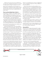
The Absolute Best Right Way To Do It
e method specified by AES48 is to use balanced lines
and tie the cable shield to the metal chassis (right where
it enters the chassis) at both ends of the cable.
A balanced line requires three separate conduc-
tors, two of which are signal (+ and –) and one shield
(see Figure 1a). e shield serves to guard the sensitive
audio lines from interference. Only by using balanced
line interconnects can you guarantee (yes, guarantee)
hum-free results. Always use twisted pair cable. Chas-
sis tying the shield at each end also guarantees the best
possible protection from RFI [radio frequency interfer-
ence] and other noises [neon signs, lighting dimmers].
Neil Muncy
1
, an electroacoustic consultant and
seasoned veteran of years of successful system design,
chairs the AES Standards Committee (SC-05-05)
working on this subject. He tirelessly tours the world
giving seminars and dispensing information on how to
successfully hook-up pro audio equipment
2
. He makes
the simple point that it is absurd that you cannot go
out and buy pro audio equipment from several different
manufacturers, buy standard off-the-shelf cable assem-
blies, come home, hook it all up and have it work hum
and noise free. Plug and play. Sadly, almost never is
this the case, despite the science and rules of noise-free
interconnect known and documented for over 60 years
(see References for complete information).
It all boils down to using balanced lines, only bal-
anced lines, and nothing but balanced lines. is is why
they were developed. Further, that you tie the shield to
the chassis, at the point it enters the chassis, and at both
ends of the cable (more on ‘both ends’ later).
Since standard XLR cables come with their shields
tied to pin 1 at each end (the shells are not tied, nor
need be), this means equipment using 3-pin, XLR-type
connectors must tie pin 1 to the chassis (usually called
chassis ground) — not the audio signal ground as is
most common.
Figure 1b. Recommmended practice.
CASE
(+)
(–)
COMMON (WRONG) PRACTICE RECOMMENDED PRACTICE
(–)
(+)
OPTIONAL
CASE
1
2
33
1
2
CHASSIS
GROUND
SIGNAL
GROUND
CHASSIS
GROUND
CHASSIS
GROUND
Not using signal ground is the most radical depar-
ture from common pro-audio practice. Not that there
is any argument about its validity. ere isn’t. is is
the right way to do it. So why doesn’t audio equipment
come wired this way? Well, some does, and since 1993,
more of it does. at’s when Rane started manufac-
turing some of its products with balanced inputs and
outputs tying pin 1 to chassis. So why doesn’t everyone
do it this way? Because life is messy, some things are
hard to change, and there will always be equipment in
use that was made before proper grounding practices
were in effect.
Unbalanced equipment is another problem: it is
everwhere, easily available and inexpensive. All those
RCA and ¼" TS connectors found on consumer equip-
ment; effect-loops and insert-points on consoles; signal
processing boxes; semi-pro digital and analog tape
recorders; computer cards; mixing consoles; et cetera.
e next several pages give tips on how to suc-
cessfully address hooking up unbalanced equipment.
Unbalanced equipment when “blindly” connected with
fully balanced units starts a pattern of hum and unde-
sirable operation, requiring extra measures to correct
the situation.
The Next Best Right Way To Do It
e quickest, quietest and most foolproof method to
connect balanced and unbalanced is to transformer
isolate all unbalanced connections. See Figure 2.
Many manufacturers provide several tools for this
task, including Rane. Consult your audio dealer to ex-
plore the options available.
e goal of these adaptors is to allow the use of
standard cables. With these transformer isolation
boxes, modification of cable assemblies is unnecessary.
Virtually any two pieces of audio equipment can be
successfully interfaced without risk of unwanted hum
and noise.
Figure 2. Transformer Isolation
NOT CONNECTED
AT CHASSIS
(PLASTIC JACK)
EARTH GROUNDED
METAL ENCLOSURE
CHASSIS IS
GROUNDED TO PIN
1
1/4”
TIP-SLEEVE
CASE LUG MAY
CONNECT TO
CHASSIS
(NOT REQUIRED)
TRANSFORMER
UNBALANCED BALANCED
3
1
2

Interconnection-4
Another way to create the necessary isolation is to
use a direct box. Originally named for its use to convert
the high impedance, high level output of an electric
guitar to the low impedance, low level input of a re-
cording console, it allowed the player to plug “directly”
into the console. Now this term is commonly used to
describe any box used to convert unbalanced lines to
balanced lines.
The Last Best Right Way To Do It
If transformer isolation is not an option, special
cable assemblies are a last resort. e key here is to
prevent the shield currents from flowing into a unit
whose grounding scheme creates ground loops (hum)
in the audio path (i.e., most audio equipment).
It is true that connecting both ends of the shield is
theoretically the best way to interconnect equipment
–though this assumes the interconnected equipment is
internally grounded properly. Since most equipment is
not internally grounded properly, connecting both ends
of the shield is not often practiced, since doing so usu-
ally creates noisy interconnections.
A common solution to these noisy hum and buzz
problems involves disconnecting one end of the shield,
even though one can not buy off-the-shelf cables with
the shield disconnected at one end. e best end to dis-
connect is the receiving end. If one end of the shield is
disconnected, the noisy hum current stops flowing and
away goes the hum — but only at low frequencies. A
ground-sending-end-only shield connection minimizes
the possibility of high frequency (radio) interference
since it prevents the shield from acting as an antenna
to the next input. Many reduce this potential RF inter-
ference by providing an RF path through a small ca-
pacitor (0.1 or 0.01 microfarad ceramic disc) connected
from the lifted end of the shield to the chassis. (is is
referred to as the “hybrid shield termination” where the
sending end is bonded to the chassis and the receiving
end is capacitively coupled. See Neutrik’s EMC-XLR
for example.) e fact that many modern day install-
ers still follow this one-end-only rule with consistent
success indicates this and other acceptable solutions to
RF issues exist, though the increasing use of digital and
wireless technology greatly increases the possibility of
future RF problems.
If you’ve truly isolated your hum problem to a spe-
cific unit, chances are, even though the documentation
indicates proper chassis grounded shields, the suspect
unit is not internally grounded properly. Here is where
special test cable assemblies, shown in Figure 3, really
come in handy. ese assemblies allow you to connect
the shield to chassis ground at the point of entry, or to
pin 1, or to lift one end of the shield. e task becomes
more difficult when the unit you’ve isolated has multi-
ple inputs and outputs. On a suspect unit with multiple
cables, try various configurations on each connection
to find out if special cable assemblies are needed at
more than one point.
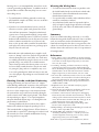
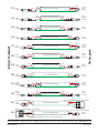
See Figure 4 for suggested cable assemblies for your
particular interconnection needs. Find the appropri-
ate output configuration (down the left side) and then
match this with the correct input configuration (across
the top of the page.) en refer to the following pages
for a recommended wiring diagram.
Ground Lifts
Many units come equipped with ground lift switches.
In only a few cases can it be shown that a ground lift
switch improves ground related noise. (Has a ground
lift switch ever really worked for you?) In reality, the
presence of a ground lift switch greatly reduces a unit’s
ability to be “properly” grounded and therefore im-
mune to ground loop hums and buzzes. Ground lifts
are simply another Band-Aid
®
to try in case of ground-
ing problems. It is true that an entire system of prop-
erly grounded equipment, without ground lift switches,
is guaranteed (yes guaranteed) to be hum free. e
problem is most equipment is not (both internally and
externally, AC system wise) grounded properly.
Most units with ground lifts are shipped so the unit
is “grounded” — meaning the chassis is connected to
audio signal ground. (is should be the best and is
the “safest” position for a ground lift switch.) If after
hooking up your system it exhibits excessive hum or
Figure 3. Test cable
TEST
WIRE
GROUND CLIP
FEMALE
MALE
1
C
2
3
1
2
3
RED
BLACK
SHIELD
RED
BLACK
SHIELD
2-CONDUCTOR SHIELDED CABLE

Interconnection-5
buzzing, there is an incompatibility somewhere in the
system’s grounding configuration. In addition to these
special cable assemblies that may help, here are some
more things to try:
1. Try combinations of lifting grounds on units sup-
plied with lift switches (or links). It is wise to do this
with the power off!
2. If you have an entirely balanced system, verify all
chassis are tied to a good earth ground, for safety’s
sake and hum protection. Completely unbalanced
systems never earth ground anything (except cable
TV, often a ground loop source). If you have a mixed
balanced and unbalanced system, do yourself a favor
and use isolation transformers or, if you can’t do
that, try the special cable assemblies described here
and expect it to take many hours to get things quiet.
May the Force be with you.
3. Balanced units with outboard power supplies (wall
warts or “bumps” in the line cord) do not ground the
chassis through the line cord. Make sure such units
are solidly grounded by tying the chassis to an earth
ground using a star washer for a reliable contact.
(Rane always provides this chassis point as an exter-
nal screw with a toothed washer.) Any device with
a 3-prong AC plug, such as an amplifier, may serve
as an earth ground point. Rack rails may or may not
serve this purpose depending on screw locations and
paint jobs.
Floating, Pseudo, and Quasi-Balancing
During inspection, you may run across a ¼" output
called floating unbalanced, sometimes also called psue-
do-balanced or quasi-balanced. In this configuration,
the sleeve of the output stage is not connected inside
the unit and the ring is connected (usually through a
small resistor) to the audio signal ground. is allows
the tip and ring to “appear” as an equal impedance,
not-quite balanced output stage, even though the out-
put circuitry is unbalanced.
Floating unbalanced often works to drive either a
balanced or unbalanced input, depending if a TS or
TRS standard cable is plugged into it. When it hums, a
special cable is required. See drawings #11 and #12, and
do not make the cross-coupled modification of tying
the ring and sleeve together.
References
1. Neil A. Muncy, “Noise Susceptibility in Analog and Digi-
tal Signal Processing Systems,” presented at the 97th AES
Convention of Audio Engineering Society in San Fran-
cisco, CA, Nov. 1994.
2. Grounding, Shielding, and Interconnections in Analog
& Digital Signal Processing Systems: Understanding the
Basics; Workshops designed and presented by Neil Muncy
and Cal Perkins, at the 97th AES Convention of Audio
Engineering Society in San Francisco, CA, Nov. 1994.
3. e entire June 1995 AES Journal, Vol. 43, No. 6, available
$6 members, $11 nonmembers from the Audio Engineer-
ing Society, 60 E. 42nd St., New York, NY, 10165-2520.
4. Phillip Giddings, Audio System Design and Installation
(SAMS, Indiana, 1990).
5. Ralph Morrison, Noise and Other Interfering Signals
(Wiley, New York, 1992).
6. Henry W. Ott, Noise Reduction Techniques in Electronic
Systems, 2nd Edition (Wiley, New York, 1988).
7. Cal Perkins, “Measurement Techniques for Debugging
Electronic Systems and eir Instrumentation,” e Pro-
ceedings of the 11th International AES Conference: Audio
Test & Measurement, Portland, OR, May 1992, pp. 82-92
(Audio Engineering Society, New York, 1992).
8. Macatee, RaneNote: “Grounding and Shielding Audio
Devices,” Rane Corporation, 1994.
9. Philip Giddings, “Grounding and Shielding for Sound and
Video,” S&VC, Sept. 20th, 1995.
10. AES48-2005: AES standard on interconnections —
Grounding and EMC practices — Shields of connectors
in audio equipment containing active circuitry (Audio
Engineering Society, New York, 2005).
Band-Aid is a registered trademark of Johnson & Johnson
Winning the Wiring Wars
• Use balanced connections whenever possible, with
the shield bonded to the metal chassis at both ends.
• Transformer isolate all unbalanced connections
from balanced connections.
• Use special cable assemblies when unbalanced lines
cannot be transformer isolated.
• Any unbalanced cable must be kept under 10 feet
(3 m) in length. Lengths longer than this will ampli-
fy all the nasty side effects of unbalanced circuitry's
ground loops.
Summary
If you are unable to do things correctly (i.e. use fully
balanced wiring with shields tied to the chassis at both
ends, or transformer isolate all unbalanced signals
from balanced signals) then there is no guarantee that
a hum-free interconnect can be achieved, nor is there a
definite scheme that will assure noise-free operation in
all configurations.

Interconnection-6
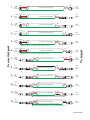
Figure 4. Interconnect chart for locating correct cable assemblies on the following pages.
Note: (A) This configuration uses an “off-the-shelf” cable.
Note: (B) This configuration causes a 6 dB signal loss. Compensate by “turning the system up” 6 dB.
To Input
MALE
BALANCED XLR
¼" BALANCED
TRS (TIP-RING-SLEEVE)
¼" OR 3.5mm
UNBALANCED
TS (TIP-SLEEVE)
UNBALANCED RCA BALANCED
EUROBLOCK
From Output
1234
6521
10987
121187
12112221
16 23
23
151413
20
2424
191817
BB
BB
AA
AA
AA
FEMALE BALANCED XLR
(NOT A TRANSFORMER,
NOR A CROSS-COUPLED
OUTPUT STAGE)
FEMALE BALANCED XLR
(EITHER A TRANSFORMER
OR A CROSS-COUPLED
OUTPUT STAGE)
¼” BALANCED TRS
(NOT A TRANSFORMER,
NOR A CROSS-COUPLED
OUTPUT STAGE)
¼” BALANCED TRS
(EITHER A TRANSFORMER
OR A CROSS-COUPLED
OUTPUT STAGE)
¼” FLOATING UNBALANCED
TRS (TIP-RING-SLEEVE)
(SLEEVE IN UNIT = NC)
¼” OR 3.5 mm
UNBALANCED
TS (TIP-SLEEVE)
UNBALANCED RCA
(TIP-SLEEVE)
CABLE
CONNECTORS
BALANCED
EUROBLOCK
+ to +
–
to –
SHIELD ONLY
TO XLR PIN 1
+
to
+
–
to –
SHIELD NC
+ to +
–
to
–
SHIELD NC
+ to +
–
to
–
SHIELD ONLY
TO EUROBLOCK
+ to +
–
to
–
SHIELD NC
+ to +
–
to –
SHIELD ONLY
TO TRS SLEEVE
+ to +
–
to –
GROUND
to
GROUND
+ to +
–
to –
GROUND
to
GROUND

Interconnection-7
10
9
S=SHIELD
R=NC
T=RED
S=SHIELD
R=NC
T=RED
8
7
S=SHIELD
R=BLACK
T=RED
S=SHIELD
R=BLACK
T=RED
MALE
6
5
3=BLACK
BLACK
4
3
3=NC
2=RED
1=SHIELD
SHIELD
SHIELD
2
FEMALE
1
3=BLACK
2=RED
1=SHIELD
MALE
B
B
B
B
S=NC
R=BLACK
T=RED
S=SHIELD
R=BLACK
T=RED
11
CROSS-COUPLED OUTPUT ONLY: CONNECT PIN 1 TO PIN 3 AT THIS END
AND SET GROUND LIFT SWITCH TO ‘GROUNDED’ (IF PRESENT).
CROSS-COUPLED OUTPUT ONLY: CONNECT PIN 1 TO PIN 3 AT THIS END
AND SET GROUND LIFT SWITCH TO ‘GROUNDED’ (IF PRESENT).
CROSS-COUPLED OUTPUT ONLY: CONNECT RING TO SLEEVE
AT THIS END AND SET GROUND LIFT SWITCH TO ‘GROUNDED’ (IF PRESENT).
1
3
2
3
1
C
2
3
1
C
2
3
1
C
2
3
1
C
2
3
1
C
2
3
1
C
2
1
3
2
To Input
From Output
RED
BLACK
RED
BLACK
SHIELD
RED
BLACK
BLACK
FEMALE
FEMALE
3=BLACK
2=RED
1=SHIELD
RED
RED
SHIELD
RED
SHIELD
SHIELD
RED
RED
BLACK
N/C
N/C
N/C
RED
BLACK
RED
SHIELD N/C
BLACK
RED
BLACK
RED
3=NC
2=RED
1=SHIELD
2=RED
1=SHIELD
3=BLACK
2=RED
1=NC
3=BLACK
2=RED
1=NC
3=BLACK
2=RED
1=SHIELD
SHIELD
FEMALE
FEMALE
FEMALE
RED
SHIELD
RED
BLACK
SHIELD
SHIELD
RED
BLACK
RED
BLACK
BLACK
RED
RED
SHIELD
RED
SHIELD
RED
SHIELD
RED
SHIELD
RED
BLACK
2-CONDUCTOR SHIELDED CABLE
2-CONDUCTOR SHIELDED CABLE
2-CONDUCTOR SHIELDED CABLE
2-CONDUCTOR SHIELDED CABLE
2-CONDUCTOR SHIELDED CABLE
2-CONDUCTOR SHIELDED CABLE
2-CONDUCTOR SHIELDED CABLE
1-CONDUCTOR SHIELDED CABLE
1-CONDUCTOR SHIELDED CABLE
1-CONDUCTOR SHIELDED CABLE
1-CONDUCTOR SHIELDED CABLE
S=NC
R=BLACK
T=RED
S=SHIELD
T=RED
S=SHIELD
T=RED
S=SHIELD
T=RED
S=BLACK
T=RED
S=BLACK
T=RED
S=BLACK
T=RED
S=BLACK
T=RED
12
S=SHIELD
R=BLACK
T=RED
S=BLACK
T=RED
CROSS-COUPLED OUTPUT ONLY: CONNECT RING TO SLEEVE
AT THIS END AND SET GROUND LIFT SWITCH TO ‘GROUNDED’ (IF PRESENT).
BLACK
SHIELD
RED
BLACK
RED
2-CONDUCTOR SHIELDED CABLE

Interconnection-8
DOC 102907
©Rane Corporation 10802 47th Ave. W., Mukilteo WA 98275-5000 USA TEL 425-355-6000 FAX 425-347-7757 WEB www.rane.com
22
21
MALE
(ANY UNBALANCED CONNECTOR)
(ANY UNBALANCED CONNECTOR)
(CHECK: NO STANDARD POLARITY ON EUROBLOCKS)
(CHECK: NO STANDARD POLARITY ON EUROBLOCKS)
20
19
18
17
16
15
MALE
A
14
13
MALE
A
A
A
A
A
1
3
2
1
2
3
1
2
3
To Input
From Output
S=SHIELD
R=BLACK
T=RED
S=SHIELD
R=BLACK
T=RED
S=SHIELD
R=BLACK
T=RED
S=SHIELD
R=BLACK
T=RED
S=SHIELD
R=BLACK
T=RED
23
S=BLACK
T=RED
S=BLACK
T=RED
S=BLACK
T=RED
S=BLACK
T=RED
S=SHIELD
T=RED
S=SHIELD
T=RED
S=SHIELD
T=RED
S=SHIELD
T=RED
S=SHIELD
T=RED
S=SHIELD
T=RED
S=SHIELD
T=RED
S=SHIELD
T=RED
3=BLACK
2=RED
1=SHIELD
3=BLACK
2=RED
1=SHIELD
3=BLACK
2=RED
1=SHIELD
SHIELD
BLACK
SHIELD
RED
BLACK
SHIELD
RED
BLACK
RED
SHIELD
SHIELD
BLACK
RED
SHIELD
BLACK
RED
SHIELD
BLACK
RED
SHIELD
BLACK
RED
SHIELD
BLACK
RED
SHIELD
RED
SHIELD
RED
SHIELD
RED
SHIELD
RED
BLACK
RED
N/C
N/C
BLACK
RED
BLACK
RED
BLACK
RED
RED
SHIELD
RED
SHIELD
RED
SHIELD
RED
24
S=BLACK
T=RED
CROSS-COUPLED OUTPUT ONLY: CONNECT BLACK TO SHIELD AT THIS END
AND SET GROUND LIFT SWITCH TO ‘GROUNDED’ (IF PRESENT).
BLACK
SHIELD
RED
BLACK
RED
2-CONDUCTOR SHIELDED CABLE
2-CONDUCTOR SHIELDED CABLE
2-CONDUCTOR SHIELDED CABLE
2-CONDUCTOR SHIELDED CABLE
S=BLACK
T=RED
SHIELD
BLACK
RED
BLACK
RED
2-CONDUCTOR SHIELDED CABLE
2-CONDUCTOR SHIELDED CABLE
2-CONDUCTOR SHIELDED CABLE
2-CONDUCTOR SHIELDED CABLE
1-CONDUCTOR SHIELDED CABLE
1-CONDUCTOR SHIELDED CABLE
1-CONDUCTOR SHIELDED CABLE
1-CONDUCTOR SHIELDED CABLE
–
+
–
+

La page est en cours de chargement...
La page est en cours de chargement...
La page est en cours de chargement...
La page est en cours de chargement...
-
 1
1
-
 2
2
-
 3
3
-
 4
4
-
 5
5
-
 6
6
-
 7
7
-
 8
8
-
 9
9
-
 10
10
-
 11
11
-
 12
12
-
 13
13
-
 14
14
-
 15
15
-
 16
16
-
 17
17
-
 18
18
-
 19
19
-
 20
20
-
 21
21
-
 22
22
-
 23
23
-
 24
24


Rane ME60S Manuel utilisateur
- Catégorie
- Équipement musical supplémentaire
- Taper
- Manuel utilisateur
dans d''autres langues
- English: Rane ME60S User manual
Documents connexes
Autres documents
-
dbx 1215 Manuel utilisateur
-
dbx 2031 Le manuel du propriétaire
-
-
dbx 1231 Le manuel du propriétaire
-
Yamaha GQ1031BII Le manuel du propriétaire
-
-
-
AudioSource EQ 10.1 Manuel utilisateur
-
dbx DBX20 Le manuel du propriétaire
-