Aeroflex ATC-5000NG Getting Started Manual
- Taper
- Getting Started Manual

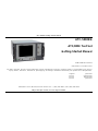
ATC-5000NG
ATC/DME Test Set
Getting Started Manual
EXPORT CONTROL WARNING: This document contains controlled technical data under the jurisdiction
of the Export Administration Regulations (EAR), 15 CFR 730-774. It cannot be transferred to any foreign
third party without the specific prior approval of the U.S. Department of Commerce, Bureau of Industry
and Security (BIS). Violations of these regulations are punishable by fine, imprisonment, or both.
Issue-4

ATC-5000NG Getting Started Manual
Subject to Export Control, see Cover Page for details.
ATC-5000NG
ATC/DME Test Set
Getting Started Manual
PUBLISHED BY Aeroflex
COPYRIGHT Aeroflex 2017
All rights reserved. No part of this publication may be reproduced, stored in a retrieval system, or transmitted in any form or
by any means, electronic, mechanical, photocopying, recording or otherwise without the prior permission of the publisher.
Original June 2015
Issue-2 August 2015
Issue-3 March 2016
Issue-4 June 2017
10200 West York / Wichita, Kansas 67215 U.S.A. / (316) 522-4981 / FAX (316) 529-5330

ATC-5000NG Getting Started Manual
Subject to Export Control, see Cover Page for details.
This manual contains essential information relating to initial use of the
Unit. Aeroflex recommends the operator become familiar with the
Operation Manual contained on the accompanying CD-ROM.
Aeroflex updates Test Set software on a routine basis. As a result, the
examples may show images from earlier software versions. Images are
updated when appropriate.

ATC-5000NG Getting Started Manual
Subject to Export Control, see Cover Page for details.
1
Product Warranty
Refer to http://ats.aeroflex.com/warranty for the Product
Warranty information.
Electromagnetic Compatibility
Double shielded and properly terminated external interface
cables must be used with this equipment when interfacing
with the REMOTE Connector.
For continued EMC compliance, all external cables must be
shielded and 3 meters or less in length.
Nomenclature Statement
In this manual, ATC-5000NG, Test Set or Unit refers to the
ATC-5000NG ATC/DME Test Set.
Declaration of Conformity
The Declaration of Conformity Certificate included with the
Unit should remain with the Unit.
Aeroflex recommends the operator reproduce a copy of the
Declaration of Conformity Certificate to be stored with the
Operation Manual for future reference.
Software Version
Aeroflex updates Test Set software on a routine basis. As a
result, examples may show images from earlier software
versions. Images are updated when appropriate.

ATC-5000NG Getting Started Manual
Subject to Export Control, see Cover Page for details.
2
Precautions
SAFETY FIRST - TO ALL OPERATIONS PERSONNEL
General Conditions of Use
This product is designed and tested to comply with the
requirements of IEC/EN61010-1 ‘Safety requirements f or
electrical equipment for measurement, control and laboratory
use’ for Clas s I portable equi pment and is for use in a
pollution degree 2 environment. The equipment is designed
to operate from installation supply Category II.
The ATC-5000NG should be protected from liquids such as
spills, leaks, etc. and precipitation such as rain, snow, etc.
When moving the equipment from a cold to hot environment,
allow the temperature of the equipment to stabilize before the
Unit is connected to an AC power supply to avoid
condensation forming. The equipment must only be operated
within the environmental conditions specified in the product
specifications.
This product is not approved for use in hazardous
atmospheres or medical applications. If the equipment is to
be used in a safety-related application, such as avionics or
military applications, the suitability of the product must be
assessed and approved for use by a competent person.
Refer all servicing of Unit to Qualified Technical Personnel.
PROTECTION PROVIDED BY EQUIPMENT
MAY BE IMPAIRED IF THE TEST SET IS
USED IN A MANNER NOT SPECIFIED BY
THE MANUFACTURER.
AVERTISSEMENT
LA PROTECTION FOURNIE AVEC
L'EQUIPEMENT PEUT S'AVERER
INEFFICACE EN CAS
D'UTILISATION D'UNE MANIERE
NON SPECIFIEE PAR LE
FABRICANT.
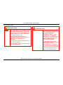
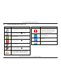
Safety Identification in Technical Manual
This manual uses the following terms to draw attention to
possible safety hazards that may exist when operating or
servicing this equipment:
IDENTIFIES CONDITIONS OR ACTIVITIES
THAT, IF IGNORED, CAN RESULT IN
EQUIPMENT OR PROPERTY DAMAGE, E.G.
FIRE.
IDENTIFIES CONDITIONS OR ACTIVITIES
THAT, IF IGNORED, CAN RESULT IN
PERSONAL INJURY OR DEATH.

ATC-5000NG Getting Started Manual
Subject to Export Control, see Cover Page for details.
3
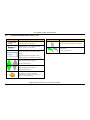
Safety Symbols in Manuals and on Units
CAUTION: Refer to accompanying documents.
(Symbol refers to specific CAUTIONS
represented on the Unit and clarified in the text.)
Indicates a Toxic hazard.
Indicates item is static sensitive.
AC TERMINAL: Terminal that may supply or be
supplied with AC or alternating voltage.
Indicates a fuse (AC or DC).
HOT SURFACE: This surface may be hot to the
touch.
Case, Cover or Panel Removal
Opening the Case Assembly exposes the operator to
electrical hazards that may result in electrical shock or
equipment damage. Do not operate this Test Set with the
Case Assembly open.
AVERTISSEMENT | ATTENTION
L'ouverture de l'enceinte expose l'opérateur à des dangers
électriques pouvant être à l'origine d'un choc ou de
l'endommagement de l'équipement. Ne faites pas fonctionner
ce Test Set avec son enceinte ouverte.
Equipment Grounding Protection
Improper grounding of equipment can result in electrical
shock.
AVERTISSEMENT | ATTENTION
Une masse défectueuse de l'équipement peut être à l'origine
d'un choc électrique.

ATC-5000NG Getting Started Manual
Subject to Export Control, see Cover Page for details.
4
Case, Cover or Panel Removal
Opening the Case Assembly exposes the operator to
electrical hazards that may result in electrical shock or
equipment damage. Do not operate this Test Set with the
Case Assembly open.
AVERTISSEMENT | ATTENTION
L'ouverture de l'enceinte expose l'opérateur à des dangers
électriques pouvant être à l'origine d'un choc ou de
l'endommagement de l'équipement. Ne faites pas fonctionner
ce Test Set avec son enceinte ouverte.
Equipment Grounding Protection
Improper grounding of equipment can result in electrical
shock.
AVERTISSEMENT | ATTENTION
Une masse défectueuse de l'équipement peut être à l'origine
d'un choc électrique.
Use of Probes
To prevent electrical shock or damage to equipment: Verify
that all the connections between the equipment and a device
under test do not exceed maximum port ratings for voltage,
current and power.
AVERTISSEMENT | ATTENTION
Pour éviter tout choc élect rique ou D’endom m ageR
l'équipement:Vérifiez que toutes les interconnexions entre
l'équipement et un périphérique testé ne dépassent pas les
valeurs maximales pour la tension, le courant et la puissance
DE CHAQUE PORT.
DMM Measurement Category
The Digital Multimeter (DMM) is classified in Measurement
Category II. Measurement Category II is designated for
equipment which performs measurements on circuits directly
connected to low voltage installation.

ATC-5000NG Getting Started Manual
Subject to Export Control, see Cover Page for details.
5
Power Cords
The AC Power Cord included with the Test Set, or an
appropriate replacement, should be used to connect the Test
Set to a grounded AC power supply. Failure to ground the
Test Set may expose the operator to hazardous voltage
levels.
To connect the Test Set to a Class II (ungrounded)
2-terminal socket outlet, fit the power cord with either a
3-pin Class I plug used in conjunction with an adapter
incorporating a ground wire or fit the power cord with a
Class II plug containing an integral ground wire. The ground
wire must be securely fastened to ground; grounding one
terminal on a 2-terminal socket does not provide adequate
protection.
Power cords must be in good operating condition. Power
cords must not be frayed or broken, nor expose bare wiring.
Using a damaged power cord may expose the operator to
hazardous voltage levels.
International Power Requirements
The AC power cord must meet local regulations and power
requirements. Check with local standards and regulations to
ensure the power cord being used meets all local safety
regulations.

ATC-5000NG Getting Started Manual
Subject to Export Control, see Cover Page for details.
6
EMI (Electromagnetic Interference)
SIGNAL GENERATORS CAN BE A SOURCE
OF ELECTROMAGNETIC INTERFERENCE
(EMI) TO COMMUNICATION RECEIVERS.
SOME TRANSMITTED SIGNALS CAN CAUSE
DISRUPTION AND INTERFERENCE TO
COMMUNICATION SERVICE OUT TO A
DISTANCE OF SEVERAL MILES. USER OF
THIS EQUIPMENT SHOULD SCRUTINIZE
ANY OPERATION THAT RESULTS IN
RADIATION OF A SIGNAL (DIRECTLY OR
INDIRECTLY) AND SHOULD TAKE
NECESSARY PRECAUTIONS TO AVOID
POTENTIAL COMMUNICATION
INTERFERENCE PROBLEMS.
ATTENTION
LES GENERATEURS DE SIGNAUX
PEUVENT CONSTITUER UNE
SOURCE D'INTERFERENCES
ELECTROMAGNETIQUES (IME)
POUR LES RECEPTEURS RADIO.
CERTAINS SIGNAUX EMIS
PEUVENT PROVOQUER DES
INTERFERENCES ET DES
INTERRUPTIONS DES
COMMUNICATIONS SUR UNE
DISTANCE DE PLUSIEURS
KILOMETRES. L'UTILISATEUR DE
CET EQUIPEMENT DOIT EXAMINER
SOIGNEUSEMENT TOUT
FONCTIONNEMENT PROVOQUANT
LE RAYONNEMENT D'UN SIGNAL
(DIRECT OU INDIRECT) ET IL DOIT
PRENDRE LES DISPOSITIONS
NECESSAIRES AFIN D'EVITER DES
PROBLEMES POTENTIELS
D'INTERFERENCES SUR LES
COMMUNICATIONS.

ATC-5000NG Getting Started Manual
Subject to Export Control, see Cover Page for details.
7
Input Overload
REFER TO PRODUCT SPECIFICATIONS FOR
MAXIMUM INPUT RATINGS FOR INPUT
CONNECTORS.
ATTENTION
REPORTEZ-VOUS AUX
SPECIFICATIONS DU PRODUIT
POUR LES CLASSIFICATIONS
D'ENTREE MAXIMUM SUR LES
CONNECTEURS D'ENTREE.
Toxic Hazards
SOME OF THE COMPONENTS USED IN
THIS EQUIPMENT MAY INCLUDE RESINS
AND OTHER MATERIALS WHICH GIVE OFF
TOXIC FUMES IF INCINERATED. TAKE
APPROPRIATE PRECAUTIONS IN THE
DISPOSAL OF THESE ITEMS.
AVERTISSEMENT
CERTAINS DES COMPOSANTS
UTILISES DANS CET
EQUIPEMENT PEUVENT
CONTENIR DES RESINES ET
D'AUTRES MATERIAUX QUI
PRODUIRONT DES EMANATIONS
TOXIQUES EN CAS
D'INCINERATION. PRENEZ
TOUTES LES DISPOSITIONS
NECESSAIRES LORS DE LA MISE
AU REBUT DE CES
EQUIPEMENTS.

ATC-5000NG Getting Started Manual
Subject to Export Control, see Cover Page for details.
8
Toxic Hazards (cont)
BERYLLIA
BERYLLIA (BERYLLIUM OXIDE) IS USED IN
THE CONSTRUCTION OF SOME OF THE
COMPONENTS IN THIS EQUIPMENT.
THIS MATERIAL, WHEN IN THE FORM OF
FINE DUST OR VAPOR AND INHALED INTO
THE LUNGS, CAN CAUSE A RESPIRATORY
DISEASE. IN ITS SOLID FORM, AS USED
HERE, IT CAN BE HANDLED SAFELY,
HOWEVER, AVOID HANDLING CONDITIONS
WHICH PROMOTE DUST FORMATION BY
SURFACE ABRASION.
USE CARE WHEN REMOVING AND
DISPOSING OF THESE COMPONENTS. DO
NOT PUT THE COMPONENTS IN THE
GENERAL INDUSTRIAL OR DOMESTIC
WASTE OR DISPATCH BY POST. THE
COMPONENTS SHOULD BE SEPARATELY
AND SECURELY PACKED AND CLEARLY
IDENTIFIED TO SHOW THE NATURE OF
THE HAZARD AND THEN DISPOSED OF IN
A SAFE MANNER BY AN AUTHORIZED
TOXIC WASTE CONTRACTOR.
OXYDE DE BERYLLIUM
AVERTISSEMENT
DU BERYLLIUM (OXYDE DE
BERYLLIUM) EST UTILISE DANS
LA FABRICATION DE CERTAINS
DES COMPOSANTS DE CET
EQUIPEMENT.
CE MATERIAU PEUT
PROVOQUER UNE AFFECTION
DES VOIES RESPIRATOIRES
LORSQU'IL SE PRESENTE SOUS
LA FORME D'UNE POUSSIERE
FINE OU DE VAPEUR ET QU'IL
ATTEINT LES POUMONS. SOUS
SA FORME SOLIDE, TEL QU'IL
EST UTILISE ICI, IL PEUT ETRE
MANIPULE SANS DANGER, MAIS
IL EST PREFERABLE D'EVITER
TOUTE FORME DE
MANIPULATION POUVANT
AMENER LA FORMATION DE
POUSSIERES PAR ABRASION
DES SURFACES.

ATC-5000NG Getting Started Manual
Subject to Export Control, see Cover Page for details.
9
Toxic Hazards (cont)
OXYDE DE BERYLLIUM
AVERTISSEMENT
SOYEZ PRUDENT LORS DE LA
DEPOSE ET DE LA MISE AU
REBUT DE CES COMPOSANTS.
NE LES TRAITEZ PAS EN TANT
QUE DECHETS INDUSTRIELS OU
MENAGERS HABITUELS; NE LES
INTRODUISEZ PAS DANS LE
CIRCUIT POSTAL. ILS DOIVENT
ETRE EMBALLES SEPAREMENT
ET SOLIDEMENT, ET
CLAIREMENT IDENTIFIES AFIN
DE PRESENTER LA NATURE DU
DANGER ET D'ETRE ENSUITE
MIS AU REBUT SANS DANGER
PAR UNE ENTREPRISE
AUTORISEE DE TRAITEMENT
DES DECHETS TOXIQUES.

ATC-5000NG Getting Started Manual
Subject to Export Control, see Cover Page for details.
10
Toxic Hazards (cont)
BERYLLIUM COPPER
SOME MECHANICAL COMPONENTS WITHIN
THIS INSTRUMENT ARE MANUFACTURED
FROM BERYLLIUM COPPER. THIS IS AN
ALLOY WITH A BERYLLIUM CONTENT OF
APPROXIMATELY 5% THAT REPRESENTS
NO RISK IN NORMAL USE.
THIS MATERIAL SHOULD NOT BE
MACHINED, WELDED OR SUBJECTED TO
ANY PROCESS WHERE HEAT IS
INVOLVED.
THIS MATERIAL MUST BE DISPOSED OF
AS “SPECIAL WASTE.”
THIS MATERIAL MUST NOT BE DISPOSED
OF BY INCINERATION.
CUPROBERYLLIUM
AVERTISSEMENT
CERTAINS COMPOSANTS
MECANIQUES A L'INTERIEUR DE
CET INSTRUMENT SONT
FABRIQUES AVEC DU
CUPROBERYLLIUM. IL S'AGIT
D'UN ALLIAGE CONTENANT
ENVIRON 5 % DE BERYLLIUM. IL
NE PRESENTE AUCUN RISQUE
DANS LE CADRE D'UNE
UTILISATION NORMALE.
CE MATERIAU NE DOIT PAS
ETRE USINE, SOUDE OU SOUMIS
A AUCUN PROCESSUS
IMPLIQUANT DE LA CHALEUR.
IL DOIT ETRE MIS AU REBUT EN
TANT QUE « DECHET SPECIAL ».
IL NE DOIT PAS ÊTRE MIS AU
REBUT PAR INCINERATION.

ATC-5000NG Getting Started Manual
Subject to Export Control, see Cover Page for details.
11
Static Sensitive Components
CAUTION
THIS EQUIPMENT CONTAINS PARTS
SENSITIVE TO DAMAGE
BY ELECTROSTATIC DISCHARGE (ESD)
This equipment contains components sensitive to damage by
Electrostatic Discharge (ESD). All personnel performing
maintenance or calibration procedures should have
knowledge of accepted ESD practices and/or be ESD
certified.
Table of Contents
Service Upon Receipt of Material ................................ 12
Unpacking............................................................ 12
Checking Unpacked Equipment .............................. 13
Specifications ........................................................... 15
Installation ............................................................... 16
Safety Precautions ............................................... 16
Complying with Instructions .............................. 16
AC Power Requirements ................................... 16
Ventilation ...................................................... 16
Grounding Power Cord ..................................... 16
Operating Safety .............................................. 17
Installation Procedure ........................................... 17
Bench Use ...................................................... 17
Rack Mount ..................................................... 17
External Cleaning ...................................................... 18
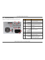
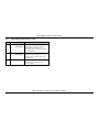
Controls, Connectors and Indicators ............................ 19
Front Panel .......................................................... 19
Rear Panel ........................................................... 20
Power On/Off Procedures ........................................... 22
Power ON Test Set ............................................... 22
Power OFF Test Set .............................................. 22
Touch Screen ............................................................ 23
Screen Features and Icons ......................................... 23
Menus and Screens ................................................... 26

ATC-5000NG Getting Started Manual
Subject to Export Control, see Cover Page for details.
12
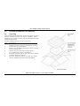
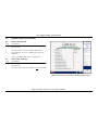
1.0 SERVICE UPON RECEIPT OF MATERIAL
1.1 Unpacking
Special-design packing material inside the shipping container
provides maximum protection for the ATC-5000NG. Avoid
damaging the shipping container and packing material during
equipment unpacking.
Use the following steps to unpack the Test Set:
STEP PROCEDURE
1. Cut and remove the sealing tape on top of the
shipping container and open the shipping container.
2. Remove the top packing mold.
3. Remove ATC-5000NG and packing material from the
bottom packing mold.
4. Remove the protective plastic bag from the
ATC-5000NG and inspect the contents.
5. Place the protective plastic bag and packing material
inside the shipping container.
6. Store the shipping container for future use should
the ATC-5000NG need to be returned/shipped.

ATC-5000NG Getting Started Manual
Subject to Export Control, see Cover Page for details.
13
1.2 Checking Unpacked Equipment
Check the equipment for damage incurred during shipment.
If the equipment has been damaged or if items seem to be
absent from the shipment, report the damage and/or
discrepancies to Aeroflex Customer Service.
Contact:
Aeroflex
Attn: Customer Service
10200 West York Street
Wichita, Kansas 67215
Telephone: (800) 835-2350 (U.S. only)
(316) 522-4981
FAX: (316) 529-5330
email: americas.service@cobham.com
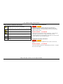
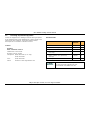
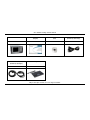
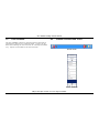
Standard Items
DESCRIPTION
PART
NUMBER
QTY
ATC-5000NG
138156
1
Manual, Getting Started (Paper)
139189
1
Manual, Operation (CD)
139188
1
Power Cable (AC) (110 Use)
(US Only)
62302
1
Power Cables (AC) (220 Use)
(Europe)
64020
1
Touchpad
114114
1
Refer to the ATC-5000NG Operation Manual
for Optional Items available for the
ATC-5000NG ATC/DME Test Set.

ATC-5000NG Getting Started Manual
Subject to Export Control, see Cover Page for details.
14
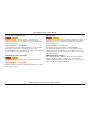
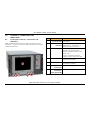
ATC-5000NG
Manual, Getting Started
(Paper)
Manual, Operation
(CD)
Power Cable (AC)
(110 Use) (US Only)
138156
139189
139188
62302
Operation / ICW Manual
(61105 (1002-6200-2C0)
Power Cable ( AC ) ( North America )
( 27478 )
Power Cables (AC)
(220 Use) (Europe)
Touchpad
64020
114114

ATC-5000NG Getting Started Manual
Subject to Export Control, see Cover Page for details.
15
2.0 SPECIFICATIONS
ENVIRONMENTAL / PHYSICAL
Overall Dimensions
10.5 in (H) X 19 in (W) X 24 in (D)
(26.7 cm, 48.3 cm, 60.9 cm)
Weight
41 lbs. (19 kg)
AC INPUT POWER
Voltage Range
100 to 240 VAC, 50 to 60 Hz
Usage Environment
Indoor Use
Operating Temperature
0C to +40C
23C (5C) Full Specified Performance
Storage Temperature
0C to +71C
Relative Humidity
0% to 95% non-condensing
Degree of Protection
IPX-0
(Specifications are subject to change without notice.)

ATC-5000NG Getting Started Manual
Subject to Export Control, see Cover Page for details.
16
3.0 INSTALLATION
3.1 Safety Precautions
The following safety precautions must be observed during
installation and operation. Aeroflex assumes no liability for
failure to comply with any safety precaution outlined in this
manual.
3.1.A Complying with Instructions
Installation/operating personnel should not attempt to install
or operate the Test Set without reading and complying with
instructions contained in this manual. All procedures
contained in this manual must be performed in exact
sequence and manner described.
3.1.B AC Power Requirements
The ATC-5000NG power supply operates over a voltage
range of 100 to 120 VAC at 60 Hz or 220 to 240 VAC at
50 Hz.
3.1.C Ventilation
The RGS-2000NG is air-cooled by fans that draw air through
vents in the case. Do not onstruct the air vents while the
instrument is in use. Avoid standing the instrument on or
close to other equipment that is hot.
3.1.D Grounding Power Cord
Use a 3-prong AC Power Cord to connect the Test Set to a
grounded AC Power Supply.
DO NOT USE A THREE-PRONG TO TWO-
PRONG ADAPTER PLUG. DOING SO
CREATES A SHOCK HAZARD BETWEEN
THE CHASSIS AND ELECTRICAL GROUND.
AVERTISSEMENT
N’UTILISEZ PAS D’ADAPTATEUR
À TROIS BROCHES SUR UNE
PRISE À DEUX BROCHES.
L'INOBSERVATION DE CETTE
CONSIGNE PEUT CRÉER UN
DANGER DE CHOC ENTRE LE
CHÂSSIS ET LA MASSE
ÉLECTRIQUE.
For AC operation, the AC Line Cable, connected to the
External DC Power Supply, is equipped with a standard
three-prong plug and must be connected to a properly
grounded three-prong receptacle.
It is the customer's responsibility to:
Have a qualified electrician check receptacle(s) for
proper grounding.
Replace any standard two-prong receptacle(s) with
properly grounded three-prong receptacle(s).

ATC-5000NG Getting Started Manual
Subject to Export Control, see Cover Page for details.
17
3.1.E Operating Safety
DUE TO POTENTIAL FOR ELECTRICAL
SHOCK WITHIN THE TEST SET, THE CASE
ASSEMBLY MUST BE CLOSED WHEN THE
TEST SET IS CONNECTED TO AN
EXTERNAL POWER SOURCE.
AVERTISSEMENT
L'ENCEINTE DU TEST SET DOIT
ETRE FERMEE EN RAISON DE
CHOCS ELECTRIQUES
POSSIBLES LORSQUE
L'APPAREIL EST CONNECTE A
UNE SOURCE D'ALIMENTATION
EXTERNE.
Extreme care should be exercised when performing any
operations preceded by a CAUTION or WARNING label.
CAUTION labels appear where possibility of damage to
equipment exists and WARNING labels denote conditions
where bodily injury or death may result.
3.2 Installation Procedure
3.2.A Bench Use
STEP PROCEDURE
1. Set the ATC-5000NG into operating position.
2. Connect the AC Power Cable from the AC INPUT
Connector to an external AC power source (100 to
240 VAC at 60 to 50 Hz).
The AC Power Cable is used to fully
disconnect the Test Set from AC Power. The
Test Set should not be positioned so the
disconnection of the AC Power Cable is
prevented.
3. Set the Power Switch (on the Test Set Rear Panel)
to the ON position (I).
4. Press the Power Switch (on the Test Set Front
Panel). The Power Switch Indicator lights and the
Test Set starts the power-up sequence.
3.2.B Rack Mount
Contact Aeroflex for information on installing the
ATC-5000NG in a rack.
La page est en cours de chargement...
La page est en cours de chargement...
La page est en cours de chargement...
La page est en cours de chargement...
La page est en cours de chargement...
La page est en cours de chargement...
La page est en cours de chargement...
La page est en cours de chargement...
La page est en cours de chargement...
La page est en cours de chargement...
La page est en cours de chargement...
La page est en cours de chargement...
La page est en cours de chargement...
La page est en cours de chargement...
-
 1
1
-
 2
2
-
 3
3
-
 4
4
-
 5
5
-
 6
6
-
 7
7
-
 8
8
-
 9
9
-
 10
10
-
 11
11
-
 12
12
-
 13
13
-
 14
14
-
 15
15
-
 16
16
-
 17
17
-
 18
18
-
 19
19
-
 20
20
-
 21
21
-
 22
22
-
 23
23
-
 24
24
-
 25
25
-
 26
26
-
 27
27
-
 28
28
-
 29
29
-
 30
30
-
 31
31
-
 32
32
-
 33
33
-
 34
34


Aeroflex ATC-5000NG Getting Started Manual
- Taper
- Getting Started Manual
dans d''autres langues
- English: Aeroflex ATC-5000NG
Documents connexes
Autres documents
-
Poly VVX 601 Guide de démarrage rapide
-
Polycom VVX 601 Guide de démarrage rapide
-
COBHAM AXRF RF Subsystem Getting Started
-
Whirlpool ADI 074 Mode d'emploi
-
Velleman DVM3218 Manuel utilisateur
-
HQ Power VDL400RF Manuel utilisateur
-
AL-KO Silver 470 E Premium Manuel utilisateur
-
-
Perel WAHR 15 Manuel utilisateur