Samsung HW-J650 Manuel utilisateur
- Catégorie
- Récepteurs de musique Bluetooth
- Taper
- Manuel utilisateur
Ce manuel convient également à

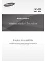
Wireless Audio - Soundbar
Imagine the possibilities
Thank you for purchasing this Samsung product.
To receive more complete service, please register your product at
www.samsung.com/register
User manual
HW-J650
HW-J651

2
GETTING STARTED
FEATURES
GETTING STARTED
Streaming Music Services
The Soundbar makes diving into all your favourite music
easier than ever before, thanks to its Wi-Fi capabilities.
Simply access the Samsung Multiroom App to
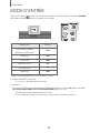
experience the best of the internet’s subscription
streaming music services.
Surround Sound Expansion
The Surround Sound Expansion feature adds depth and
spaciousness to your listening experience.
TV SoundConnect
Connect your TV and Soundbar easily through Bluetooth
with TV Sound Connect. The absence of trailing wires
between the Soundbar and TV allows you to showcase
the slim and sleek design of both systems, while
maintaining a clean look in your living environment. Easily
control the Soundbar and TV from a single TV remote.
Music Source Sharing (= Multiroom Play)
Controlling and sharing one music source across multiple
audio devices in various locations is made easy with
Multiroom Link. The mobile app remotely controls volume
and music on your system across different devices,
including your TV, Soundbar, Home Entertainment
System and Blu-ray Disc Player. Enjoy the audio you
want, where you want.
HDMI
HDMI transmits video and audio signals simultaneously,
and provides a clearer picture.
The unit is also equipped with the ARC function which
lets you listen to sound from your TV through the
Soundbar via an HDMI cable. This function is only
available if you connect the unit to an ARC compliant TV.
USB Host Support
You can connect and play music files from external USB
storage devices such as MP3 players, USB flash
memory, etc. using the Soundbar's USB HOST function.
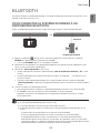
Bluetooth Function
You can connect a Bluetooth device to the Soundbar
and enjoy music with high quality stereo sound, all
without wires!
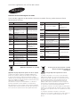
LICENCES
Manufactured under Licence from Dolby Laboratories.
Dolby and the double-D symbol are trademarks of Dolby
Laboratories.
For DTS patents, see http://patents.dts.com.
Manufactured under licence from DTS Licensing Limited.
DTS, the Symbol, & DTS and the Symbol together are
registered trademarks, and DTS 2.0 Channel is a
trademark of DTS, Inc. © DTS, Inc. All Rights Reserved.
The terms HDMI and HDMI High-Definition Multimedia
Interface, and the HDMI Logo are trademarks or
registered trademarks of HDMI Licensing LLC in the
United States and other countries.

3
ENG
GETTING STARTED
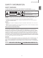
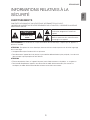
SAFETY INFORMATION
SAFETY WARNINGS
TO REDUCE THE RISK OF ELECTRIC SHOCK, DO NOT REMOVE THE COVER (OR BACK).
NO USER-SERVICEABLE PARTS ARE INSIDE. REFER SERVICING TO QUALIFIED SERVICE PERSONNEL.
CAUTION
RISK OF ELECTRIC SHOCK
DO NOT OPEN
This symbol indicates “dangerous voltage”
inside the product that presents a risk of electric
shock or personal injury.
This symbol indicates important instructions
accompanying the product.
WARNING : To reduce the risk of fire or electric shock, do not expose this appliance to rain or moisture.
CAUTION : TO PREVENT ELECTRIC SHOCK, MATCH WIDE BLADE OF PLUG TO WIDE SLOT, FULLY INSERT.
• This apparatus shall always be connected to a AC outlet with a protective grounding connection.
• To disconnect the apparatus from the mains, the plug must be pulled out from the mains socket, therefore the
mains plug shall be readily operable.
CAUTION
• Do not expose this apparatus to dripping or splashing. Do not put objects filled with liquids, such as vases on the
apparatus.
• To turn this apparatus off completely, you must pull the power plug out of the wall socket. Consequently, the power
plug must be easily and readily accessible at all times.
Wiring the Main Power Supply Plug (UK Only)
IMPORTANT NOTICE
The mains lead on this equipment is supplied with a moulded plug incorporating a fuse. The value of the fuse is
indicated on the pin face of the plug and if it requires replacing, a fuse approved to BS1362 of the same rating must
be used. Never use the plug with the fuse cover removed. If the cover is detachable and a replacement is required,
it must be of the same colour as the fuse fitted in the plug. Replacement covers are available from your dealer. If the
fitted plug is not suitable for the power points in your house or the cable is not long enough to reach a power point,
you should obtain a suitable safety approved extension lead or consult your dealer for assistance. However, if there is
no alternative to cutting off the plug, remove the fuse and then safely dispose of the plug. Do not connect the plug to a
mains socket as there is a risk of shock hazard from the bared flexible cord. Never attempt to insert bare wires directly
into a mains socket. A plug and fuse must be used at all times.
IMPORTANT
The wires in the mains lead are coloured in accordance with the following code:– BLUE = NEUTRAL BROWN = LIVE
As these colours may not correspond to the coloured markings identifying the terminals in your plug, proceed as
follows:– The wire coloured BLUE must be connected to the terminal marked with the letter N or coloured BLUE or
BLACK. The wire coloured BROWN must be connected to the terminal marked with the letter L or coloured BROWN
or RED.
WARNING : DO NOT CONNECT EITHER WIRE TO THE EARTH TERMINAL WHICH IS MARKED WITH THE
LETTER E OR BY THE EARTH SYMBOL , OR COLOURED GREEN OR GREEN AND YELLOW.

4
GETTING STARTED
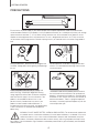
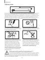
PRECAUTIONS
99.1mm 99.1mm
68.6
mm
99.1mm
Ensure that the AC power supply in your house complies with the power requirements listed on the identification
sticker located on the back of your product. Install your product horizontally, on a suitable base (furniture), with enough
space around it for ventilation (7~10 cm). Make sure the ventilation slots are not covered. Do not place the unit on
amplifiers or other equipment which may become hot. This unit is designed for continuous use. To fully turn off the
unit, disconnect the AC plug from the wall outlet. Unplug the unit if you intend to leave it unused for a long period of
time.
During thunderstorms, disconnect the AC plug from the
wall outlet. Voltage peaks due to lightning could damage
the unit.
Protect the product from moisture (i.e. vases), and
excess heat (e.g. a fireplace) or equipment creating
strong magnetic or electric fields. Disconnect the power
cable from the AC supply if the unit malfunctions. Your
product is not intended for industrial use. It is for
personal use only. Condensation may occur if your
product has been stored in cold temperatures. If
transporting the unit during the winter, wait approximately
2 hours until the unit has reached room temperature
before using.
Do not expose the unit to direct sunlight or other heat
sources. This could lead to overheating and cause the
unit to malfunction.
The batteries used with this product contain chemicals
that are harmful to the environment. Do not dispose of
batteries in the general household trash. Do not dispose
of batteries in a fire. Do not short circuit, disassemble, or
overheat the batteries. There is a danger of explosion if
the battery is incorrectly replaced. Replace only with the
same or equivalent type.
D
uri
ng
thu
nde
rstorms
dis
connect t
he
AC
plu
g
D
o not expose
th
eu
nit
to
di
rect s
unl
igh
toro
th
WARNING, DO NOT INGEST BATTERY, CHEMICAL BURN HAZARD, The remote control supplied with
this product contains a coin/button cell battery. If the coin/button cell battery is swallowed, it can cause
severe internal burns in just 2 hours and can lead to death. Keep new and used batteries away from
children. If the battery compartment does not close securely, stop using the product and keep it away
from children. If you think batteries might have been swallowed or placed inside any part of the body, seek immediate
medical attention.

5
ENG
GETTING STARTED
● Figures and illustrations in this User Manual are
provided for reference only and may differ from
actual product appearance.
● An administration fee may be charged if either
(a) an engineer is called out at your request and
there is no defect with the product (i.e. where
the user manual has not been read).
(b) you bring the unit to a repair centre and there is
no defect with the product (i.e. where the user
manual has not been read).
● You will be informed of the administration fee
amount before a technician visits.
CONTENTS
2 GETTING STARTED
2 Features
3 Safety Information
6 What’s Included
7 DESCRIPTIONS
7 Top / Front Panel
8 Rear / Bottom Panel
9 Remote Control
11 INSTALLATION
11 Installing the Wall Mount
11 Installation Precautions
12 Installing the Bracket without Referring to the
Wall-Mount Installation Guide
13 Detaching the Wall Mount
14 CONNECTIONS
14 Connecting the Subwoofer
16 Connecting to a TV
16 Connections with TV Using Optical (Digital)
Cable
17 Connections with TV Using HDMI (Digital)
Cable
17 TV SoundConnect
19 Connections with External Device
19 HDMI Cable
19 Optical or AUX Cable
20 USB
22 FUNCTIONS
22 Input Mode
23 Bluetooth
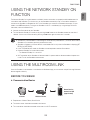
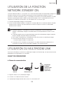
25 Using the Network Standby On
Function
25 Using the Multiroom Link
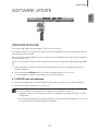
27 Software Update
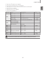
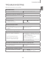
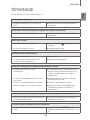
29 TROUBLESHOOTING
29 Troubleshooting
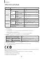
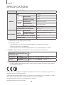
30 APPENDIX
30 Specifications

6
GETTING STARTED
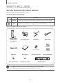
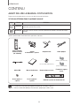
WHAT’S INCLUDED
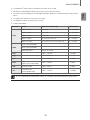
BEFORE READING THE USER’S MANUAL
Note the following terms before reading the user manual.
+ Icons used in this manual
Icon Term Definition
Caution
Indicates a situation where a function does not operate or settings may be cancelled.
Note
Indicates tips or instructions on the page that help you operate a function.
Check for the supplied accessories shown below.
Remote Control /
Lithium Battery
(3V : CR2032)
Power Cord : 2EA DC Adapter Optical Cable
(For Power Cord)
(Wall Mount L)
(Wall Mount R)
USB Cable User Manual Toroidal Ferrite Core Bracket-Wall Mount
Holder-Screw 1: 2EA Holder-Screw 2: 2EA Wall Mount Guide
● The appearance of the accessories may differ slightly from the illustrations above.
● Use the dedicated USB cable to connect external USB devices to the unit.

7
ENG
DESCRIPTIONS
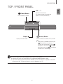
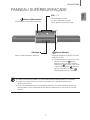
TOP / FRONT PANEL
(Power) Button
Turns the power on and off.
VOL. - / +
Controls the volume level.
The numeric value of the volume level
appears in the front panel display.
Display
Displays the current mode.
(Source) Button
Selects the D.IN, AUX, HDMI, BT, TV, or USB
input.
● While the unit is powered on, pressing the
(Source) button for more than 3
seconds sets the button to act as the
( Mute) button. To cancel the ( Mute)
button setup, press the (Source) button
for more than 3 seconds again.
● When you plug in the AC cord, the power key will work in 4 to 6 seconds.
● When you turn on this unit, there will be a 4 to 5 second delay before it produces sound.
● If you want to enjoy the sound only from the Soundbar, you must turn off the TV's speakers in the Audio
Setup menu of your TV. Refer to the owner's manual supplied with your TV.
DESCRIPTIONS

8
DESCRIPTIONS
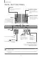
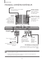
REAR / BOTTOM PANEL
AUX IN OPTICAL IN
HDMI IN
HDMI OUT
(TV-ARC)
AUX IN
HDMI IN
HDMI OUT
(TV-ARC)
OPTICAL IN
LAN 5V 0.5A
LAN 5V 0.5A
DC 24V
SPK ADDWi-Fi SETUP
DC 24V
SPK ADDWi-Fi SETUP
DC 24V (Power Supply In)
Connect the DC power adaptor to the power
supply jack, and then connect the AC power
adaptor plug to a wall outlet.
HDMI IN
Inputs digital video and audio
signals simultaneously using an
HDMI cable. Use when
connecting a supported external
device.
HDMI OUT (TV-ARC)
Outputs digital video and
audio signals simultaneously
using an HDMI cable.
OPTICAL IN (D.IN)
Connect to the digital
(optical) output of an external
device.
AUX IN
Connect to the Analogue output of an
external device.
LABEL
SPK ADD
Press this button to
connect the
Soundbar to a HUB.
(not supplied)
Wi-Fi SETUP
Press this button to
connect your Soundbar to
your network using Wi-Fi
setup.
LAN
Lets you connect to a network using a
LAN cable.
(USB Port)
Connect USB devices here to play files
on the devices.
● When disconnecting the power cable of the AC power adaptor from a wall outlet, pull the plug.
Do not pull the cable.
● Do not connect this unit or other components to an AC outlet until all connections between components
are complete.

9
ENG
DESCRIPTIONS
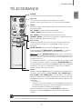
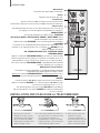
REMOTE CONTROL
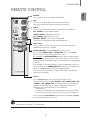
Anynet+
Press the Anynet+ button to turn the Anynet+ function on or off.
(Default : Auto Power Link OFF, ON - ANYNET+ / OFF - POWER LINK or OFF
- ANYNET+ / ON - POWER LINK). The Anynet+ function lets you control the
Soundbar with the remote from an Anynet+ compatible Samsung TV. The
Soundbar must be connected to the TV via an HDMI cable.
* Auto Power Link
Synchronizes the Soundbar to a connected Optical source via the Optical
jack so it turns on automatically when you turn on your TV. (See page 16)
You can also activate Wi-Fi SETUP function by pressing and holding Anynet+
button on the remote for over 7 seconds.
Repeat
Press to set the Repeat function during music playback from a USB device.
OFF - REPEAT : Cancells Repeat Playback.
TRACK - REPEAT : Repeatedly play a track.
ALL - REPEAT : Repeatedly play all tracks.
RANDOM - REPEAT : Plays tracks in random order.
(A track that has already been played may be played again.)
Mute
You can turn the volume down to 0 with the push of a button.
Press again to restore the sound to the previous volume level.
SOURCE
Press to select a source connected to the Soundbar.
Skip Forward
If there is more than one file on the device you are playing, and you press
the $ button, the next file is selected.
SOUND CONTROL
(*Use the
#
,
$
buttons to adjust level.)
Press to select TREBLE, BASS, or AUDIO SYNC. Then, use the
#
,
$
buttons to adjust the Treble, Bass volume from -3 to +3.
Press and hold the SOUND CONTROL button for about 5 seconds to adjust
the sound for each frequency band. 150Hz, 300Hz, 600Hz, 1.2KHz, 2.5KHz,
5KHz, and 10KHz are selectable and each can be adjusted to a setting between
-6 and +6.
If the Soundbar is connected to a digital TV and the video appears out of sync
with the audio, press the SOUND CONTROL button to sync the audio with the
video. Use the
#
,
$
buttons to set the audio delay between
0 ms and 300 ms. In USB mode, TV mode, and BT mode, the Audio Sync
function may not available.
● Soundbar is a Samsung proprietary name.
● Operate the TV using the TV's remote control.

10
DESCRIPTIONS
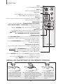
STREAMING MUSIC
Press STREAMING MUSIC button to listen to an Internet radio station. Each
time you press this button, the Soundbar switches to the next default station,
cycling through the 3 default stations.
To use the STREAMING MUSIC function, the soundbar must be connected to
the network. (See page 25)
DRC (Dynamic Range Control) *
Lets you apply dynamic range control to Dolby Digital, Dolby Digital Plus, and
Dolby TrueHD audio.
Press and hold the STREAMING MUSIC button, then the DRC (Dynamic
Range Control) function toggles between ON and OFF.
WOOFER
(* Use the
#
,
$
buttons to adjust woofer volume.)
Press the WOOFER button. Then, use the
#
,
$
buttons to adjust Subwoofer
volume from -12, -6 to +6.
You can also activate SPK ADD function of the soundbar by pressing and
holding WOOFER button of the remote for over 5 seconds.
SOUND
Surr.Sound adds depth and spaciousness to the sound. Pressing the
SOUND button repeatedly cycles through the Surr.Sound settings :
ON - SURROUND SOUND, OFF - SURROUND SOUND
Volume
Adjusts the volume level of the unit.
Power
Turns the Soundbar on and off.
SOUND EFFECT
You can select the sound modes - STANDARD (Original Sound), MUSIC,
VOICE, SPORTS, CINEMA, and NIGHT MODE - depending on the content
you want to listen to.
Select the STANDARD mode if you want to enjoy the original sound.
Play / Pause
Press the
&
button to pause the playing of a file temporarily.
Press the
&
button again to play the selected file.
Skip Back
If there is more than one file on the device you are playing, and you press the
#
button, the previous file is selected.
INSTALLING THE BATTERY IN THE REMOTE CONTROL
1. Use a suitable coin to turn the
remote control's battery cover
counterclockwise to remove it
as shown in the figure above.
2. Insert a 3V lithium battery. Keep the
positive (+) pole facing up when inserting
the battery. Put the battery cover on and
align the '●' marks side by side as
shown in the figure above.
3. Use a suitable coin to
turn the remote control
battery cover clockwise
as far as it will go to fix it
in place.

11
ENG
INSTALLATION
INSTALLING THE WALL MOUNT
You can use the wall mount bracket to mount this unit on a wall.
I NSTALLATION PRECAUTIONS
●
Install on a vertical wall only.
● For the installation, avoid a location with high temperature or humidity, or a wall that cannot sustain the weight of
the set.
● Check the strength of the wall. If the wall is not strong enough to support the unit, reinforce the wall or install the
unit on a different wall that can support the unit's weight.
● Purchase and use the fixing screws or anchors appropriate for the kind of wall you have (plaster board, iron board,
wood, etc.). If possible, fix the support screws into wall studs.
● Purchase wall mounting screws according to the type and thickness of the wall you will mount the Soundbar on.
- Diameter : M5
- Length: L 35 mm or longer recommended.
● Connect cables from the unit to external devices before you install it on the wall.
● Make sure the unit is turned off and unplugged before you install it. Otherwise, it may cause an electric shock.
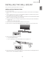
5 cm or more
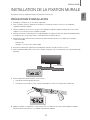
1. Place the installation guide against the wall surface.
• The installation guide must be level.
• If the TV is mounted on the wall, install the Soundbar at least 5 cm below the TV.
2. Mark the location where the screws will go through on the wall, and then remove the installation guide. Next, drill
holes for the screws using an appropriately sized drill bit.
INSTALLATION

12
INSTALLATION
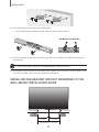
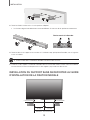
3. Fasten the wall mounts and screws to the marked locations.
• The left and right mounts are different shapes. Make sure to position them correctly.
DC 24V
SPK ADD
Wi-Fi SETUP
Wall Mounting the SoundBar
4. Secure the two holder screws to the screw holes on the back of the Soundbar's main body, one on the left and
one on the right.
● Insert the USB cable into the back of the Soundbar before installing it on the wall.
5. Set the holder screws on the back of the Soundbar into the grooves of the wall mounts. For safe installation, make
sure to push the holder screws all the way to the bottom of the grooves.
I NSTALLING THE BRACKET WITHOUT REFERRING TO THE
WALL-MOUNT INSTALLATION GUIDE
5 cm or more
5 cm or more
16 cm 17.5 cm
Minimum 32.8 ~ 33.5 cm

13
ENG
INSTALLATION
1. Place Wall Mount L on the desired wall surface parallel to the floor as shown above. Mark the location of the
screw holes on the wall. Drill holes for the screws at the places you have marked.
2. Match the screw holes on Wall Mount L to the screw holes on the wall, and then screw one screw through the hole
in its right end. Tighten the screw until it is firmly fixed to the wall.
3. Place Wall Mount R on the desired wall surface parallel to the floor and aligned with Wall Mount L as shown
above. Mark the location of the screw holes on the wall. Drill holes for the screws at the places you have marked.
4. Match the screw holes on Wall Mount R to the screw holes on the wall, and then screw one screw through the
hole in its right end. Tighten the screw until it is firmly fixed to the wall.
• If you are mounting the Wall Mounts beneath the TV, make sure to position the mounts 5 or more cm below
the TV and to align the mounts with the centre of the TV as shown above.
5. Insert screws through the remaining holes, and then tighten.
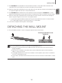
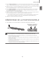
D ETACHING THE WALL MOUNT
1. Pull the Soundbar upwards as shown in the figure to separate it from the wall mounts.
Detaching the Soundbar from the
Wall Mounts
● Do not hang onto the installed unit and avoid striking or dropping the unit.
● Secure the unit firmly to the wall so that it does not fall off. If the unit falls off, it may cause an injury or
damage the product.
● When the unit is installed on a wall, please make sure that children do not pull any of the connecting
cables, as it may cause it to fall.
● For the optimal performance of a wall mount installation, install the speaker system at least 5 cm below the
TV, if the TV is mounted on the wall.
● For your safety, if you do not mount the unit on the wall, install it on a secure, flat surface where it is unlikely
to fall.

14
CONNECTIONS
● Do not connect the power cord of this product or your TV to a wall outlet until all connections between
components are complete.
● Before moving or installing this product, be sure to turn off the power and disconnect the power cord.
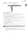
CONNECTING THE SUBWOOFER
CONNECTING TO THE SUBWOOFER AUTOMATICALLY
The main unit and subwoofer should link (connect wirelessly) automatically when the main unit and subwoofer are
turned on.
• If it is completely connected, the blue LED in the subwoofer stops blinking.
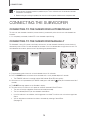
CONNECTING TO THE SUBWOOFER MANUALLY
The Subwoofer's linking ID is preset at the factory and the main unit and subwoofer should link (connect wirelessly)
automatically when the main unit and subwoofer are turned on. If the Link indicator does not light when the main unit
and subwoofer are turned on, please set the ID by following the procedure below.
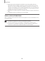
POWER
1. Plug the power cords of the main unit and subwoofer into an AC wall outlet.
2. Press the ID SET button on the back of the subwoofer with a small, pointed object for 5 seconds.
• The STANDBY indicator is turned off and the LINK indicator (Blue LED) blinks quickly.
3. While the main unit is powered off (in STANDBY mode), press and hold the (Mute) on the remote control for 5
seconds.
4. The ID SET message appears on the Soundbar's display.
5. To finalise the link, turn the main unit’s power on while the subwoofer’s Blue LED blinks.
• The main unit and the subwoofer should now be linked (connected).
• The Link indicator (Blue LED) on the subwoofer should be on.
• If the Link indicator is not solid blue, the linking process has failed. Turn off the main unit and start again from
Step 2.
• You can enjoy better sound from the wireless subwoofer by selecting a Sound Effect.
(See page 10)
CONNECTIONS

15
ENG
CONNECTIONS
● Before moving or installing the product, be sure to turn off the power and disconnect the power cord.
● If the main unit is powered off, the wireless subwoofer will be in standby mode and the STANDBY LED on
the upper side will come on after the Link indicator (Blue LED) blinks for 30 seconds.
● If you use a device that uses the same frequency (2.4GHz) as the Soundbar near the Soundbar,
interference may cause some sound interruption.
● The transmission distance of the wireless signal between the main unit and subwoofer is about 10 meters,
but may vary depending on your operating environment. If a steel-concrete or metallic wall is between the
main unit and the wireless subwoofer, the system may not operate at all, because the wireless signal
cannot penetrate metal.
● If the main unit doesn't make a wireless connection, follow steps 1-5 on the previous page to re-set the
connection between the main unit and wireless subwoofer.
● The wireless receiving antenna is built into the wireless subwoofer. Keep the unit away from water and
moisture.
● For optimal listening performance, make sure that the area around the wireless subwoofer location is clear
of any obstructions.
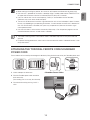
ATTACHING THE TOROIDAL FERRITE CORE SOUNDBAR
POWER CORD
You can reduce noise caused by electromagnetic radiation by fitting the ferrite core to the your Soundbar power cord.
1. Unlock and open the ferrite core.
2. Wind the Soundbar power cable around the
ferrite core twice.
(Start winding 5 to 10 cm away from the core).
3. Close the ferrite core by pressing it until it it
clicks.
DC 24V
SPK ADDWi-Fi SETUP
<Soundbar Power Cable>

16
CONNECTIONS
CONNECTING TO A TV
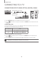
CONNECTIONS WITH TV USING OPTICAL (DIGITAL) CABLE
AUX IN
HDMI IN
HDMI OUT
(TV-ARC)
OPTICAL IN
LAN 5V 0.5A
DC 24V
SPK ADDWi-Fi SETUP
OPTICAL IN
OPTICAL OUT
OPTICAL IN
Optical Cable
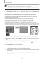
1. Connect OPTICAL IN (Audio) on the Soundbar to the OPTICAL OUT jack of the TV.
2. Press the (Source) button on the top panel of Soundbar or the SOURCE button on remote control to select
the D.IN mode.
+ Auto Power Link
If you have connected the main unit to a TV with a digital optical cable, set the Auto Power function ON to have
the Soundbar turn on automatically when you turn the TV on.
AUTO POWER LINK Display
ON
OFF - ANYNET+ / ON - POWER LINK
OFF
ON - ANYNET+ / OFF - POWER LINK
1. Connect the Soundbar and
a TV
with an Optical cable.
2. Press the (Source) button on the main unit’s top panel or the SOURCE button on the remote control to
select the
D.IN
mode.
3. Press the Anynet+ button on the remote control to toggle the Auto Power Link function on and off.
● Depending on the connected device, Auto Power Link may not function.

17
ENG
CONNECTIONS
CONNECTIONS WITH TV USING HDMI (DIGITAL) CABLE
AUX IN
HDMI IN
HDMI OUT
(TV-ARC)
OPTICAL IN
LAN 5V 0.5A
DC 24V
SPK ADDWi-Fi SETUP
HDMI IN
HDMI OUT
(TV-ARC)
HDMI OUT
(TV-ARC)
HDMI Cable
(not supplied)
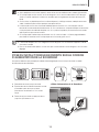
1. Connect an HDMI cable (not supplied) from the HDMI OUT (TV-ARC) jack on the back of the product to the
HDMI IN jack on your TV.
2. Press the (Source) button on the top panel of Soundbar or the SOURCE button on remote control to select
the D.IN mode.
● HDMI is an interface that enables the digital transmission of video and audio data with just a single
connector.
● If the TV provides an ARC port, connect the HDMI cable to the HDMI IN (ARC) port.
● We recommend you use a coreless HDMI cable if possible. If you use a cored HDMI cable, use one whose
diameter is less than 14 mm.
● Anynet+ must be turned on.
● This function is not available if the HDMI cable does not support ARC.
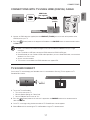
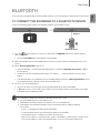
TV SOUNDCONNECT
You can enjoy TV sound through your Soundbar when it is connected to a Samsung TV that supports the TV
SoundConnect function.
Connect
1. Turn on the TV and Soundbar.
• Turn on the menu of the TV.
• Move to Speaker Settings on "Sound" tab.
• Set the "Add New Device" menu to "On".
2. Press the
(Source) button on the main unit’s top panel or the SOURCE button on the remote control to
select the TV mode.
3. On the TV, a message asking whether to enable the TV SoundConnect function appears.
4. Select <Yes> to finish connecting the TV and Soundbar using the TV's remote control.

18
CONNECTIONS
● Switching the Soundbar’s mode from TV to another mode automatically terminates TV SoundConnect.
● To connect the Soundbar to another TV, the existing connection must be terminated.
● Terminate the connection to the existing TV, and then press the
&
button on the remote control for 5
seconds to connect to another TV.
● The TV SoundConnect (SoundShare) function is supported by some Samsung TVs released from 2012 on.
Check whether your TV supports the TV SoundConnect (SoundShare) function before you begin. (For
further information, refer to the TV’s user manual.).
● If your Samsung TV was released before 2014, check the SoundShare setting menu.
● If the distance between the TV and Soundbar exceeds 10 meters, the connection may not be stable or the
audio may stutter. If this occurs, relocate the TV or Soundbar so that they are within operational range, and
then re-establish the TV SoundConnect connection.
● TV SoundConnect Operational Ranges:
- Recommended pairing range: within 2 meters.
- Recommended operational range: within 10 meters.
● The Play/Pause, Next, and Prev buttons on the Soundbar or Soundbar's remote do not control the TV.

19
ENG
CONNECTIONS
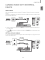
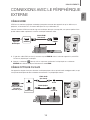
CONNECTIONS WITH EXTERNAL
DEVICE
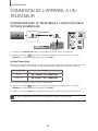
HDMI CABLE
HDMI is the standard digital interface for connecting to TVs, projectors, DVD players, Blu-ray players, set top boxes,
and more.
HDMI prevents any degradation to the signal due to conversion to analogue and maintains the video and audio
quality of the original digital source.
AUX IN
HDMI IN
HDMI OUT
(TV-ARC)
OPTICAL IN
LAN 5V 0.5A
DC 24V
SPK ADDWi-Fi SETUP
HDMI OUT HDMI IN
HDMI IN
Digital Devices
HDMI Cable
(not supplied)
1. Connect an HDMI cable (not supplied) from the HDMI IN jack on the back of the product to the HDMI OUT jack
on your digital device.
2. Press the (Source) button on the top panel of Soundbar or the SOURCE button on remote control to select
the HDMI mode.
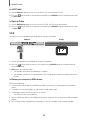
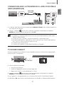
OPTICAL OR AUX CABLE
This unit comes equipped with one optical in digital jack and one audio analogue in jack, giving you two ways to
connect it to an External Devices.
AUX IN
HDMI IN
HDMI OUT
(TV-ARC)
OPTICAL IN
LAN 5V 0.5A
DC 24V
SPK ADDWi-Fi SETUP
OPTICAL IN
AUX IN
OPTICAL OUT
AUX OUT
AUX IN
OPTICAL IN
BD / DVD player /
Set-top box /
Game console
Optical Cable
Audio Cable
(not supplied)

20
CONNECTIONS
+ AUX Cable
1. Connect AUX IN (Audio) on the main unit to the AUDIO OUT jack of the Source Device.
2. Press the (Source) button on the top panel of Soundbar or the SOURCE button on remote control to select
the AUX mode.
+ Optical Cable
1. Connect OPTICAL IN (Audio) on the main unit to the OPTICAL OUT jack of the Source Device.
2. Press the
(Source) button on the top panel of Soundbar or the SOURCE button on remote control to select
the D.IN mode.
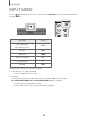
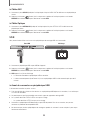
USB
You can play music files located on USB storage devices through the Soundbar.
AUX IN
HDMI IN
HDMI OUT
(TV-ARC)
OPTICAL IN
LAN 5V 0.5A
DC 24V
SPK ADD
Wi-Fi SETUP
DC14V
LAN 5V 0.5A
Display
USB port
1. Connect the USB device to the USB port on the back of the product.
2. Press the (Source) button on the main unit’s top panel or the SOURCE button on the remote control to
select the USB mode.
3. USB appears on the display screen.
• The Soundbar connection to the USB device is complete.
• The Soundbar automatically turns off (Auto Power Off) if no USB device has been connected for more than 15
minutes.
+ Before you connect a USB device
Be aware of the following:
● If the file name of a file or folder on a USB device exceeds 10 characters, it is not displayed on the Soundbar's
display.
● This product may not be compatible with certain types of USB storage media.
● The Soundbar supports the FAT16 and FAT32 file systems.
- The NTFS file system is not supported.
● Connect USB devices directly to the USB port of the product. Otherwise, you may encounter a USB compatibility
problem.
● Do not connect multiple storage devices to the product via a multi-card reader. It may not operate properly.
La page est en cours de chargement...
La page est en cours de chargement...
La page est en cours de chargement...
La page est en cours de chargement...
La page est en cours de chargement...
La page est en cours de chargement...
La page est en cours de chargement...
La page est en cours de chargement...
La page est en cours de chargement...
La page est en cours de chargement...
La page est en cours de chargement...
La page est en cours de chargement...
La page est en cours de chargement...
La page est en cours de chargement...
La page est en cours de chargement...
La page est en cours de chargement...
La page est en cours de chargement...
La page est en cours de chargement...
La page est en cours de chargement...
La page est en cours de chargement...
La page est en cours de chargement...
La page est en cours de chargement...
La page est en cours de chargement...
La page est en cours de chargement...
La page est en cours de chargement...
La page est en cours de chargement...
La page est en cours de chargement...
La page est en cours de chargement...
La page est en cours de chargement...
La page est en cours de chargement...
La page est en cours de chargement...
La page est en cours de chargement...
La page est en cours de chargement...
La page est en cours de chargement...
La page est en cours de chargement...
La page est en cours de chargement...
La page est en cours de chargement...
La page est en cours de chargement...
La page est en cours de chargement...
La page est en cours de chargement...
La page est en cours de chargement...
La page est en cours de chargement...
-
 1
1
-
 2
2
-
 3
3
-
 4
4
-
 5
5
-
 6
6
-
 7
7
-
 8
8
-
 9
9
-
 10
10
-
 11
11
-
 12
12
-
 13
13
-
 14
14
-
 15
15
-
 16
16
-
 17
17
-
 18
18
-
 19
19
-
 20
20
-
 21
21
-
 22
22
-
 23
23
-
 24
24
-
 25
25
-
 26
26
-
 27
27
-
 28
28
-
 29
29
-
 30
30
-
 31
31
-
 32
32
-
 33
33
-
 34
34
-
 35
35
-
 36
36
-
 37
37
-
 38
38
-
 39
39
-
 40
40
-
 41
41
-
 42
42
-
 43
43
-
 44
44
-
 45
45
-
 46
46
-
 47
47
-
 48
48
-
 49
49
-
 50
50
-
 51
51
-
 52
52
-
 53
53
-
 54
54
-
 55
55
-
 56
56
-
 57
57
-
 58
58
-
 59
59
-
 60
60
-
 61
61
-
 62
62


Samsung HW-J650 Manuel utilisateur
- Catégorie
- Récepteurs de musique Bluetooth
- Taper
- Manuel utilisateur
- Ce manuel convient également à
dans d''autres langues
- English: Samsung HW-J650 User manual
Documents connexes
-
Samsung HW-H430 Manuel utilisateur
-
Samsung HW-J7501R Manuel utilisateur
-
-
Samsung HW-H355 Manuel utilisateur
-
Samsung HW-J6500 Manuel utilisateur
-
Samsung HW-J355 Le manuel du propriétaire
-
Samsung HW-J6011 Manuel utilisateur
-
Samsung HW-J7500R Manuel utilisateur
-
-