
Part # 1382680 Rev 2 (12/09/10) Page 1
Users are cautioned that maintenance and repairs must be performed by a Garland authorized service agent
using genuine Garland replacement parts. Garland will have no obligation with respect to any product that has been
improperly installed, adjusted, operated or not maintained in accordance with national and local codes or installation
instructions provided with the product, or any product that has its serial number defaced, obliterated or removed,
or which has been modified or repaired using unauthorized parts or by unauthorized service agents.
For a list of authorized service agents, please refer to the Garland web site at http://www.garland-group.com.
The information contained herein, (including design and parts specifications), may be superseded and is subject
to change without notice.
GARLAND COMMERCIAL RANGES, LTD.
1177 Kamato Road, Mississauga, Ontario L4W 1X4
CANADA
Phone: 905-624-0260
Fax: 905-624-5669
Part # 1382680 Rev 2 (12/09/10) © 2005 Garland Commercial Industries, Inc.
FOR YOUR SAFETY:
DO NOT STORE OR USE GASOLINE
OR OTHER FLAMMABLE VAPORS OR
LIQUIDS IN THE VICINITY OF
THIS OR ANY OTHER
APPLIANCE
WARNING:
IMPROPER INSTALLATION, ADJUSTMENT,
ALTERATION, SERVICE OR MAINTENANCE
CAN CAUSE PROPERTY DAMAGE, INJURY,
OR DEATH. READ THE INSTALLATION,
OPERATING AND MAINTENANCE
INSTRUCTIONS THOROUGHLY
BEFORE INSTALLING OR
SERVICING THIS EQUIPMENT
PLEASE READ ALL SECTIONS OF THIS MANUAL
AND RETAIN FOR FUTURE REFERENCE.
THIS PRODUCT HAS BEEN CERTIFIED AS
COMMERCIAL COOKING EQUIPMENT AND
MUST BE INSTALLED BY PROFESSIONAL
PERSONNEL AS SPECIFIED.
IN THE COMMONWEALTH OF MASSACHUSETTS
THIS PRODUCT MUST BE INSTALLED BY A
LICENSED PLUMBER OR GAS FITTER.
For Your Safety:
Post in a prominent location, instructions to be
followed in the event the user smells gas. This
information shall be obtained by consulting
your local gas supplier.
INSTALLATION AND
OPERATION MANUAL
MASTER SERIES HEAVY DUTY GAS RANGES
AND CHAR BROILERS,
ALL M/MS/MST SERIES MODELS

Part # 1382680 Rev 2 (12/09/10)Page 2
IMPORTANT INFORMATION
WARNING:
This product contains chemicals known to the state of California to cause cancer and/or birth defects
or other reproductive harm. Installation and servicing of this product could expose you to airborne
particles of glass wool/ceramic fibers. Inhalation of airborne particles of glass wool/ceramic fibers
is known to the state of California to cause cancer. Operation of this product could expose you to
carbon monoxide if not adjusted properly. Inhalation of carbon monoxide is known to the state of
California to cause birth defects or other reproductive harm.
Keep appliance area free and clear of combustibles.

Part # 1382680 Rev 2 (12/09/10) Page 3
TABLE OF CONTENTS
IMPORTANT INFORMATION. . . . . . . . . . . . . 2
SPECIFICATIONS . . . . . . . . . . . . . . . . . . . . . . . 4
Clearance from Combustible Construction . . . . 4
Clearance from Non-Combustible
Construction. . . . . . . . . . . . . . . . . . . . . . . . . . . . . . . . . 4
INSTALLATION . . . . . . . . . . . . . . . . . . . . . . . . . 5
Rating Plate . . . . . . . . . . . . . . . . . . . . . . . . . . . . . . . . . . 5
Gas Installation . . . . . . . . . . . . . . . . . . . . . . . . . . . . . . 5
Installation of ovens equipped with casters . . . 5
Legs . . . . . . . . . . . . . . . . . . . . . . . . . . . . . . . . . . . . . . . . . 6
Ventilation and Air Supply . . . . . . . . . . . . . . . . . . . . 6
Installation of Oven Flue Riser . . . . . . . . . . . . . . . . 6
Installation Instructions for
Low Prole Backguard . . . . . . . . . . . . . . . . . . . . . . . 6
Installation Instructions for
High Prole Backguards and Shelves . . . . . . . . . . 7
Installation Instructions for
Salamander or Cheesmelter . . . . . . . . . . . . . . . . . . 7
Assembly of Battery . . . . . . . . . . . . . . . . . . . . . . . . . . 7
Optional Common Rail Installation . . . . . . . . . . . . 8
Pressure Regulators . . . . . . . . . . . . . . . . . . . . . . . . . 11
Testing and Adjustments . . . . . . . . . . . . . . . . . . . . 11
OPERATION. . . . . . . . . . . . . . . . . . . . . . . . . . . 12
Open top burners (M/MS Models) . . . . . . . . . . . 12
Open top burners (MST Models) . . . . . . . . . . . . . 12
Hot top Sections and Spectro-Top Sections
(M Models) . . . . . . . . . . . . . . . . . . . . . . . . . . . . . . . . . 12
Hot Top Sections and Spectro-Top Sections
(MS/MST Models) . . . . . . . . . . . . . . . . . . . . . . . . . . . 12
Thermostatically Controlled Griddles
(M Models) . . . . . . . . . . . . . . . . . . . . . . . . . . . . . . . . . 12
Valve Controlled Griddles (M Models) . . . . . . . . 13
Valve controlled Griddles (MS/MST Models) . . 13
Oven (Standard) . . . . . . . . . . . . . . . . . . . . . . . . . . . . 13
“RC” Convection Ovens . . . . . . . . . . . . . . . . . . . . . . 13
Char-Broiler (M.MS Models) . . . . . . . . . . . . . . . . . . 14
Char-Broiler (MST Models): . . . . . . . . . . . . . . . . . . . 14
Assembly of Char-Broiler: . . . . . . . . . . . . . . . . . . . . 15
MAINTENANCE . . . . . . . . . . . . . . . . . . . . . . . 15
Painted Finishes . . . . . . . . . . . . . . . . . . . . . . . . . . . . 15
Stainless Steel Finishes . . . . . . . . . . . . . . . . . . . . . . 15
Oven Interior (Porcelain Enamel) . . . . . . . . . . . . . 16
Oven Interior – Optional continuous Clean . . .16
Automatic Pilot Valve . . . . . . . . . . . . . . . . . . . . . . . 16
Griddle Seasoning . . . . . . . . . . . . . . . . . . . . . . . . . . 16
Griddle Cleaning . . . . . . . . . . . . . . . . . . . . . . . . . . . . 17
Open Top Burners . . . . . . . . . . . . . . . . . . . . . . . . . . 17
Top Grates
Seasoning Cast Iron Top Grates . . . . . . . . . . . . . . 17
Cast Iron Hot tops and Spectro-Heat Tops . . . . 18
ADJUSTMENTS. . . . . . . . . . . . . . . . . . . . . . . . 18
Pilot Adjustment . . . . . . . . . . . . . . . . . . . . . . . . . . . 18
Burner Gas/Air Adjustments . . . . . . . . . . . . . . . . . 18
FDO Heavy Duty Oven control . . . . . . . . . . . . . . . 19
BJWA Griddle Thermostat . . . . . . . . . . . . . . . . . . .20
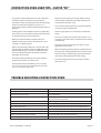
CONVECTION OVEN USER TIPS –
SUFFIX “RC” . . . . . . . . . . . . . . . . . . . . . . . . . .21
TROUBLE SHOOTING
CONVECTION OVEN . . . . . . . . . . . . . . . . . . . 21

Part # 1382680 Rev 2 (12/09/10)Page 4
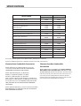
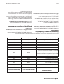
SPECIFICATIONS
MODEL NUMBER
GAS TYPE NATURAL GAS TYPE-PROPANE
INPUT (BTU/H) INPUT (BTU/H)
(M,MS)(12,43) Open Burner 24,000 20,000
MST43 Open Burner 24,000 20,000
M43-(1,2,3) Hot top burner 22,000 22,000
M43 FTR Front Open Burner 18,000 16,000
Rear French top 15,000 16,000
(M, MS)(4,42,44,54) Open Burner 35,000 35,000
MST(42,44,54) Open burner 35,000 35,000
(M,MS)(45,54,5) Spectro Heat Burner 15,000 11,000
MST45 Spctro Heat Burner
Total of 3 burners
40,000
Total of 3 burners
40,000
M(42-6,46,6,12S-6) Even Heat Hot Top Burner. 30,000 30,000
MST(42-6,46,6) Even Heat Hot Top Burner 27,000 27,000
(M,MS)47 Griddle burner 33,000 33,000
MST 47 Griddle Burner 30,000 30,000
M48 Griddle Burner 33,000 33,000
(M,MS,MST) Oven Burner 40,000 35,000
(M,MS,MST)(17,24,34) Char-Broiler 15,000 15,000
(M1R) Single deck oven section 40,000 40,000
(M2R) Double stacked ovens 80,000 80,000
Natural Gas Operating Pressure=6.0” Water Column, measured at manifold tap.
Propane Gas Operating Pressure=10.0” Water Column, measured at manifold tap.
Clearance from Combustible Construction
Models (M,MST)5(S,T) & (M,MST)45(R,RC,S,T) must be
installed with no less than six inch (6”) clearance from
combustible construction at sides and rear.
Models (M,MS,MST)42(R,RC,S,T), (M,MS,MST)
44(R,RC,S,T), (M,MS,MST)54(R,RC,S,T), (M,MS,
MST)4(S,T), (M,MST)46(R,RC,S,T), (M,MST)47
(R,RC,S,T), M47-23(R,RCS,T), M47-45(R,RC,S,T), M48(R,RCS,T),
M48-23(R,RC,S,T), M48-45(R,RC,S,T) (M,MST)(6,7,8)(S,T) must
be installed with no less than fourteen inches (14”) on the
side, and six inch (6”) rear clearance from combustible
construction.
Models (M,MS,MST)43(R,RC,S,T) must be installed with no less
than eleven inch (11”) side and six inch (6”) rear clearance
from combustible construction.
Clearance from Non-Combustible
Construction
Models (M,MS,MST)(17,24,34)B(E) are for INSTALLATION IN
NON-COMBUSTIBLE LOCATIONS ONLY with zero (0”) sides
and rear clearance. Models with sux “RC” must be installed
with zero inches (0”) side and no less than one inch (1”) rear
clearance from non-combustible construction. All other
models may be installed with zero inches (0”) sides and rear
clearance from non-combustible construction.

Part # 1382680 Rev 2 (12/09/10) Page 5
INSTALLATION
Rating Plate
When corresponding with the factory or your local
authorized factory service center regarding service problems
or replacement parts, be sure to refer to the particular unit
by the correct model number (including the prex and sux
letters and numbers) and the warranty serial number. The
rating plate axed to the unit contains this information.
We suggest installation, maintenance and repairs should be
performed by your local authorized service agency listed in
your information manual pamphlet.
In the event you have any questions concerning the
installation, use, care or service of the product, write or call
our Product Service Department.
This product must be installed by professional personnel as
specied. Garland/U.S. Range products are not approved or
authorized for home or residential use, but are intended for
commercial applications only. Garland / U.S. Range will not
provide service, warranty, maintenance or support of any
kind other than in commercial applications.
Gas Installation
Before assembly and connection check gas supply.
A. The type of gas for which the unit is equipped is stamped
on the data plate located behind the lower front panel.
Connect a unit stamped on the data plate located behind
the lower front panel. Connect a unit stamped “NAT”
only to natural gas; connect those stamped “PRO” only to
propane gas.
B. If it is a new installation have the gas authorities check
meter size and piping to assure that the unit is supplied
with sucient amount of gas pressure required to
operate the UNIT.
C. If it is additional or replacement equipment have gas
authorities check pressure to make certain that existing
meter and piping will supply fuel to the unit with not
more than 1/2” water column pressure drop.
NOTE: When checking gas pressure be sure that all other
equipment on the same gas line is on. A pressure regulator is
not supplied as standard equipment with GARLAND Heavy
Duty equipment, however a 1-1.4” pressure regulator is
sold as an option with the original purchase. If you would
like to purchase a regulator after original purchase contact
your equipment dealer. Installation must conform with the
National fuel Gas code ANSI Z223-1-1988 or latest edition,
NFPA No. 54 – Latest Edition and National electrical code
ANSI/NFPA 70-1990 or latest edition and/or local code to
assure safe and ecient operation.
In Canada, the installation must comply with
CAN/CGA-B149.1 NATURAL GAS INSTALLATION CODE, or
CAN/CGA-B149.2 PROPANE GAS INSTALLATION CODE, and
local codes where applicable.
In Canada, electrical connection must comply with
applicable sections of the Canadian Electrical Codes, C22.1
– 1990 (or latest edition), “Safety Standard for Installation,
Part 1” and C22.2 – No O-M 1982 (or latest edition), “General
Requirements, Part 2”.
NOTE: The appliance must be isolated from the gas supply
piping system by closing its individual manual shut-o (not
supplied by manufacturer) during any testing of the gas
supply piping system at test pressures equal to or less than
1/2 PSIG (3.45 KPA).
NOTE: Adequate clearance must be provided for servicing
and proper operation.
NOTE: This appliance is not recommended for residential
installation.
Installation Of Ovens Equipped With Casters
A. The installation shall be made with a connector that
complies with the Standard for Connectors for Moveable
Gas Appliances, ANSI Z21.69/CSA 6.16, Addenda Z21.69B-
2006/CSA 6.16B-2006 (or latest edition), and a quick-
disconnect device that complies with the Standard for
Quick Disconnects for Use with Gas Fuel, ANSI Z21.41/
CSA 6.9, Addenda Z21.41A-2005/CSA 6.16A-2005 (or
latest edition).
B. The front casters of the unit are equipped with brakes
to limit the movement of the range without depending
on the connector and any quick-disconnect device or its
associated piping to limit the appliance movement.

Part # 1382680 Rev 2 (12/09/10)Page 6
INSTALLATION Continued
C. Please be aware, required restraint is attached to a
bracket (which is located on the left rear caster), and if
disconnection of the restraint is necessary, be sure to
reconnect the restraint after the oven has been returned
to its originally installed position.
Legs
Raise front of the unit and block do not lay unit on its back.
Position leg insert into leg retainer opening and tap up until
it seats at collar ange. Repeat at rear of unit making sure all
four legs are adjusted to same height. Legs can be adjusted
to overcome an uneven oor.
Ventilation and Air Supply
Proper ventilation is highly important for good operation.
The ideal method of ventilating a range is the use of
a properly designed canopy which should extend
approximately six inches (6”) beyond all sides of the
appliance and six feet (6’) six inches (6”) from the oor.
A strong exhaust fan will create a vacuum in the room, for an
exhaust system vent to work properly, replacement air must
enter the room in which the vent is located.
All gas burners and pilots need sucient air to operate and
large objects should not be placed in front of this oven which
would obstruct the air ow through the front.
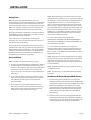
Installation of Oven Flue Riser
The oven ue is packed inside the oven for shipping
purposes. Before installing the back guard, high shelf or
range mount salamander you must install the oven ue riser.
Remove the two #10 sheet metal screws from the rear center
of the main top. Position the oven ue riser over the center
square hold with the at surface to the rear of the range.
Reinstall the two #10 sheet metal screws, securing the oven
ue riser to the rear main top.
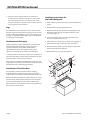
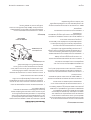
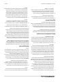
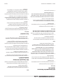
Installation Instructions for
Low Prole Backguard
1. Remove ue cap, (6), by removing six, (6), #10 sheet metal
screws.
2. Remove front panel, (5), by lifting upward.
3. With back panel, (4), still attached to the uprights, (2 & 3),
drop the uprights into the rectangular openings at the
rear of the range. (1).
4. Fasten the uprights, (2 & 3), to the range with four (4),
5/16” x 18 and at washers, (7 & 8).
5. If the range is in a battery line-up, fasten units together at
hole marked “X” with ¼” x 20 bolts, nuts and washers.
6. Reattach the front panel, (5) to the backguard with sheet
metal screws previously removed.
7. Reinstall ue cap, (6), to top of backguard.
~
~
1
"X"
"X"
2
5
8
7
3
6
9
4

Part # 1382680 Rev 2 (12/09/10) Page 7
INSTALLATION Continued
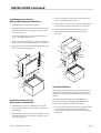
Installation Instructions for
High Prole Backguards and Shelves
1. Remove front panel, (5), by lifting upward.
2. With back panel, (4), still attached to the uprights, (2 &3),
drop the uprights into the rectangular openings at the
rear of the range, (1).
3. Fasten the uprights, (2 & 3), to the range with four, (4),
5/16” x 18 and at washers, (6 & 7).
4. If the range is in a battery line-up, fasten units together at
hole marked “X” with 1/4” x 20 bolts, nuts and washers.
5. Reattach the front panel, (5) to the backguard with sheet
metal screws previously removed.
1
"X"
"X"
2
5
8
4
3
6
7
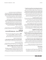
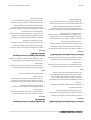
Installation Instructions for
Salamander or Cheesmelter
1. Remove front panel, (5), by removing two, (2), sheet
metal screws from the underside of the salamander or
cheesemelter.
2. With back panel, (4), still attached to the uprights, (2 & 3),
drop the uprights into the rectangular openings at the
rear of the range, (1).
3. Fasten the uprights, (2 & 3), to the range with four, (4),
5/16” x 18 and at washers, (6 & 7).
4. If the range is in a battery line-up, fasten units together at
hole marked “X” with 1/4” x 20 bolts, nuts and washers.
5. Reattach the front panel, (5) to the salamander or
cheesemelter with sheet metal screws previously
removed.
~
1
"X"
"X"
2
8
4
3
6
7
5
Garland
Assembly of Battery
All heavy duty batteried equipment is aligned and tted at
the factory, from left to right and must be installed in this
order. There is a diagram provided with every heavy duty
battery.
All models described, except model M110XMmay be
installed to battery with GARLAND M/MS/MST40 Series
Ranges, sharing common manifold connections.
A. All such units should be placed in their respective battery
position. Detach valve panels to prevent damage,
remove them from the area where the battery is being
assembled.

Part # 1382680 Rev 2 (12/09/10)Page 8
INSTALLATION Continued
B. Level each unit (to the oven rack) by adjusting the six inch
(6”) legs (refer back to Item 1 for limitations), or where
legs are not used, adjust level with shims. Readjust legs, if
required.
C. Connect units together by mating the unions at each
end of the manifold. (Adjoining units must have
matching unions, unless the union parts are of the
same specications, a leak proof connection cannot be
assured.) Hand tighten unions at this point.
D. The units should be fastened at the rear by inserting 5/16”
bolts through the holes provided at the rear of the burner
box sides. Install washer and nut and hand tighten. Be
sure of proper unit alignment in the battery before nal
tightening of these bolts or unions. Improper tightening
will cause “fanning” or “bowing” of batteried units.
The nal tightening of the union should be accomplished
by using a suitable spanner wrench. If such a wrench
is not available, the GARLAND union collar has special
ridges, and a cold chisel can be driven against these
ridges to properly seat and seal the union.
E. The manifold of this unit or the manifold of which is
a part of must be equipped with a certied pressure
regulator suitable for battery application and adjustable
for an outlet pressure at the manifold as specied on the
rating plate.
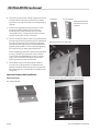
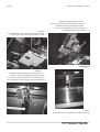
Optional Common Rail Installation
Rail Accessories
Rail Support Bracket
Spacers X2 End rail support
(Right & Left) brackets
mounted at each end
of the rail.
Rail with studs for end rail bracket.
Rail with stud to align with rail center support bracket.

Part # 1382680 Rev 2 (12/09/10) Page 9
INSTALLATION Continued
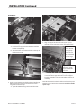
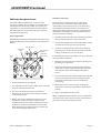
Installation
A
B
1. Install end rail support bracket.
A. Install end rail support bracket between manifold
bracket and top ange.
B. Align back holes on bracket with holes in the top of
the burner box side.
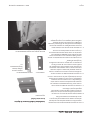
A
2. Install spacers between manifold bracket and top ange
before connecting center rail support bracket across
ranges. Be sure holes line up.
A. Spacer ts between ange and manifold bracket.
A
3. Align rail support bracket with holes (A) on top of 2
adjacent ranges and insert 2 screws and nuts to fasten.
Align studs with
holes in bracket
and range top.
Ensure nuts are
on studs prior to
being assembled
onto the range
Align holes in bracket
with hole in range
top. Assemble nuts
onto studs
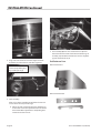
4. End rail support bracket should align as per step 1. Studs
at each end of rail align with holes in end rail support
brackets. Assemble 1 nut onto stud before and after rail
assembly.
Note: End enclosure bracket should be installed at this point
between rail and end bracket if required. See nal assembly
option step 7.

Part # 1382680 Rev 2 (12/09/10)Page 10
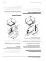
5. Align and insert stud into rail center support bracket.
Assemble nut and washer to stud after alignment.
A
A
Insert counter sink screw
and nut into top of ange of
range. 2 sides per range
6. Final Assembly:
After rail has been assembled insert athead screw and
nut to attach rail to top side of range.
A. Adjust rail level and position with nuts between rail
and bracket and secure adjustment with nuts below
the bracket. When adjustment is complete tighten
countersunk screw and nut.
A
7. Final assembly Option: If an end enclosure is required
the end enclosure bracket should be installed during rail
assembly, step #4. Mount bracket over studs and tighten
against underside of rail (A).
End Enclosure Parts
End Enclosure Rt/Lt
End Enclosure Bracket
INSTALLATION Continued

Part # 1382680 Rev 2 (12/09/10) Page 11
Pressure Regulators
1. Must have a maximum regulation capacity for the total
connected load.
2. The pressure regulator(s) installed must be listed by a
nationally recognized agency.
3. The pressure regulator(s) must have a pressure
adjustment range to allow adjustment to the manifold
pressure on the appliance rating plate.
4. Unless the manifold pressure on all connected appliances
is the same, a separate pressure regulator must be
supplied for each appliance(s) having diering manifold
pressures.
5. Gas supply lines may be connected at right, left or both
ends of a battery or at the TEE connections on spreader
plates. If ve (5) or more units are placed in a battery,
more that one (1) supply line should be used. A readily
accessible, approved type of hand shut-o valve should
be installed on each supply line.
WARNING: Local codes may require that the pressure
regulator be externally vented. This will be supplied by
others.
Testing and Adjustments
All ttings and pipe connections must be tested for
leaks. Use approved gas leak detectors, soap solutions or
equivalent, checking over and around the ttings and pipe
connections. DO NOT USE A FLAME! Accessibility to all gas
lines and ttings require that valve panel(s) lower front
panel(s), oven rack(s) be removed. It may be necessary to
remove or at least raise and securely prop griddles, hot
tops and top grates. All parts removed (including fasteners)
should be stored safely for re-use.
Testing
1. Be sure that all valves and thermostats are in the “OFF”
position.
2. Turn on the main gas supply valve. Light all top section
pilots.
3. Leak test all valves and ttings as described in the
procedure above. Correct any leaks as required and
recheck.
4. Light oven pilot.
5. If the range is provided with an oven shut-o valve
separate from the thermostat, turn this valve on and
set the thermostat at 500 degrees. If the range oven
thermostat has an “OFF” position on the dial the
thermostat is equipped with an internal, integral oven
shut-o valve. Set this thermostat dial to 500 degrees. In
both cases, gas will now ow to the oven burner.
6. Leak test all valves, ttings, etc. As above. Correct any
leaks and retest.
7. Shut o all range valves and set thermostat dials to “O’
or low position.
All units are tested and adjusted at the factory. However,
burners and pilots should be checked at installation and
adjusted if necessary.
INSTALLATION Continued

Part # 1382680 Rev 2 (12/09/10)Page 12
OPERATION
Open Top Burners (M/MS Models)
Lighting
1. Remove top grates and ring grates.
2. Check ash tubes to see they are properly positioned on
burner charge ports.
3. Light pilots.
4. Replace top grates and ring grates.
5. Turn valve completely on by rotating the knob counter-
clockwise 1/4 turn. Burner ame should be 1/2” stable
blue ame and should impinge on the underside of pot
placed on ring grate.
Shut Down
1. Turn all valves to the “O” position by rotating the knob
clockwise 1/4 turn.
2. If the unit is to be shut down for an extended period of
time, close the inline gas valve.
Open Top Burners (MST Models)
Lighting
1. Push in the gas valve and turn it anti-clockwise to the
ignition position.
2. Holding the valve fully in, light pilot burner with a match
or taper.
3. When the pilot is lit, continue to hold the valve fully in for
20 seconds, then release it. If the pilot goes out, wait for (5)
minutes, then repeat from step 1.
4. When pilot is established, push the valve in again and
turn it anti-clockwise to the desired ame setting.
5. To shut the burner o, turn the dial to the “O” position
and the safety device will disengage within (60) seconds.
Hot Top Sections And Spectro-Top Sections
(M Models)
Lighting
1. Raise or remove hot top sections. Every burner has one
pilot located at the front right side of the burner.
2. Light pilots. The pilot burner should be adjusted to
provide for rapid ignition on the burner.
3. Turn burner valve on by rotating the knob counter-
clockwise 1/4 turn. A sharp blue ame should be
approximately 1/4” high.
4. Replace hot top sections.
Shut Down
1. Turn all valves to the “OFF” position by rotating the knob
clockwise 1/4 turn.
2. If the unit is to be shut down for an extended period of
time, close the inline gas valve.
Hot Top Sections And Spectro-Top Sections
(MS/MST Models)
Lighting
1. Push in the valve and turn it anti-clockwise to the ignition
position.
2. Holding the valve fully in, light pilot burner with a match
or taper.
3. When the pilot is lit, continue to hold the valve fully in for
20 seconds, then release it. If the pilot goes out, wait for (5)
minutes, then repeat from step 1.
4. When pilot is established, push the valve in again and
turn it anti-clockwise to the desired ame setting.
5. To shut the burner o, turn the dial to the “O” position
and the safety device will disengage within (60) seconds.
Thermostatically Controlled Griddles
(M Models)
Lighting
1. Raise griddle at front and block.
2. Light Pilots located at the front right side of each burner.
3. Sensing bulbs must be fully inserted into their individual
holders which are located on the underside of the
griddle.
4. Set thermostat to maximum, one at a time. Burner
should have 5/16” stable blue ame. DO NOT ALLOW
THE GRIDDLE TO HEAT LONGER THAN 1 MINUTE! WHEN
READY TO USE THE GRIDDLE, IT MUST BE SEASONED
BEFORE ACTUAL USE, SEE “SEASONING INSTRUCTION” IN
THE MAINTENANCE SECTION.

Part # 1382680 Rev 2 (12/09/10) Page 13
OPERATION Continued
5. Lower griddle carefully into position taking extreme
caution not to leave any part of the capillary tube in the
burner compartment.
Shut Down
1. Turn all valves to the “OFF” position by rotating the knob
clockwise 1/4 turn.
2. If the unit is to shut down for an extended period of time,
close the inline gas valve.
Valve Controlled Griddles (M Models)
Lighting
1. Raise griddle at front and block.
2. Light pilots located at the front right side of each burner.
3. Turn burner valves on to full position. Burners should
have 1/2” to a 5/8” stable blue ame.
DO NOT ALLOW THE GRIDDLE TO HEAT LONGER THAN
1 MINUTE! WHEN READY TO USE THE GRIDDLE, IT MUST
BE SEASONED BEFORE ACTUAL USE, SEE “SEASONING
INSTRUCTION” IN THE MAINTENANCE SECTION.
4. Lower griddle into position.
Shut Down
1. Turn all valves to the “OFF” position by rotating the knob
clockwise 1/4 turn.
2. If the unit is to be shut down for an extended period of
time, close the inline gas valve.
Valve controlled Griddles (MS/MST Models)
1. Push in the valve and turn it anti-clockwise to the ignition
position.
2. Holding the valve fully in, light pilot burner with a match
or taper.
3. When the pilot is lit, continue to hold the valve fully in for
20 seconds, then release it. If the pilot goes out, wait for (5)
minutes, then repeat from step 1.
4. When pilot is established, push the valve in again and turn
it anti-clockwise to the desired ame setting.
5. To shut the burner o, turn the dial to the “O” position
and the safety device will disengage within (60) seconds.
Oven (Standard)
Lighting
1. Push in the main/pilot gas valve and turn it anti-clockwise
to the ignition position.
2. Holding the oven gas valve fully in, depress the red piezo
ignitor button located behind the lower drop down
panel.
3. When the pilot is lit, continue to hold the oven gas valve
fully in for 20 seconds, then release it,. If the pilot goes
out, wait for 5 minutes then repeat from step 1.
4. When pilot is established, push that gas valve in again
and turn it anti-clockwise to the full on position, then set
the thermostat to the desired temperature.
Shut Down
1. Turn the oven valve dial to the “O” position and the safety
device will disengage within 60 seconds.
2. If the range is to be shut down for an extended period of
time, close the in line gas valve.
“RC” Convection Ovens
For 115v usage, a cord and plug is provided but connection
to the electrical service must comply with local codes; or in
the absence of local codes, with the National electrical Code,
ANSI/NFPA No. 70 - (current edition).
WARNING: Electrical Grounding Instructions.
This appliance is equipped with a three pronged (grounding)
plug for your protection against shock hazard and should be
plugged directly into a properly grounded three pronged
receptacle. Do not cut or remove the grounding prong from
this plug.
POWER FAILURE NOTE: In the event of a power failure, no
attempt should be made to operate this oven. This oven is
gas operated but has electrical features, motor and door
switches.
A wiring diagram is attached to the rear of this unit.
Lighting Instructions
1. Push in the main/pilot gas valve and turn it anti-clockwise
to the ignition position.

Part # 1382680 Rev 2 (12/09/10)Page 14
OPERATION Continued
2. Holding the oven gas valve fully in, depress the red piezo
ignitor button located behind the lower drop down
panel.
3. When the pilot is lit, continue to hold the oven gas valve
fully in for 20 seconds, then release it. If the pilot goes out,
wait for 5 minutes then repeat from step 1.
4. When the pilot is established, push the gas valve in again
and turn it anti-clockwise to the full on position, then set
the thermostat to the desired temperature.
Start Up
1. Activate the power switch to “cook” position.
2. Turn oven gas valve to the on.
3. Turn the thermostat to desired setting.
Cool Down
1. Turn thermostat and oven valve o.
2. Open door.
3. Activate power to the cool down position.
Shut Down
1. Turn thermostat o.
2. Return power switch to “OFF” position.
3. Turn oven valve o.
The motor on your range convection oven is maintenance
free since it is constructed with self lubricating sealed ball
bearings. It is designed to provide durable service when
treated with ordinary care. We have a few suggestions to
follow on the care of your motor.
A. When the motor is operating, it cools itself internally by
air entering the rear of the motor case, provided proper
clearance has been allowed.
B. Since the blower wheel is in the oven cavity it is at the
same temperature as the oven. If the motor is stopped
while the oven is hot, the heat from the blower wheel is
conducted down the shaft and into the armature of the
motor. This action could shorten motor life.
C. We recommend, at the end of the bake or roasting
period, when the oven will be idle for any period of time
or before shutting down completely, that the doors
be left open, and by use of the cool-down position on
the fan switch, the fan continues to run for at least 20
minutes.
Note: The convection oven motor should never be turned
“OFF” during cooking or when the oven is “HOT”
Char-Broiler (M,MS Models)
Lighting
1. Raise or remove the cooking grates. Every group of two
(2) burners has one pilot located centrally between them.
2. Depress the piezo ignitor button to light pilots. The pilot
burner should be adjusted to provide for rapid ignition
on the burner.
3. Turn burner valve on by rotating the know anti-clockwise.
A sharp blue ame should be approximately 1/4” high.
Shut Down
1. Turn all valves to the “OFF” position “ by rotating the knob
clockwise 1/4 turn.
2. If the unit is to be shut down for an extended period of
time, close the inline gas valve.
Char-Broiler (MST Models)
Lighting
1. Raise or remove the cooking grates. Every group of two
(2) burners has one pilot located centrally between them.
2. Push in the gas valve and turn it anti-clockwise to the
ignition position.
3. Holding the gas valve fully in, depress the red piezo
ignitor button located behind the lower door panel.
4. When the pilot is lit, continue to hold the gas valve fully in
for 20 seconds, then release it. If the pilot goes out, wait for
(5) minutes then repeat from step 1.
5. When pilot is established, push the gas valve in again and
turn it anti-clockwise to the full on position, then set the
thermostat to the desired temperature.

Part # 1382680 Rev 2 (12/09/10) Page 15
Shut Down
1. Turn all valves to the “OFF” position by rotating the knob
clockwise 1/4 turn.
2. If the unit is to be shut down for an extended period of
time, close the inline gas valve.
NOTE: MODELS WITH SUFFIX “E” ARE EQUIPPED WITH
AN ELECTRIC SPARK IGNITION MODULE FOR PILOT
BURNER IGNITION. PUSHING THE SPARK BUTTON WILL
SIMULTANEOUSLY IGNITE ALL PILOTS.
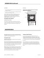
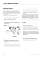
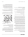
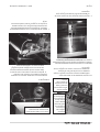
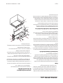
Assembly of Char-Broiler
Steel Rock Support Rods
Each broiler is supplied with 5/8” diameter steel rods to
support the briquettes. These rods are to be installed in the
grooves in the support bracket which are atop the main
burners.
Briquettes
REFER TO THE DIAGRAM BELOW FOR THE PROPER
BRIQUETTE ARRANGEMENT.
Arrangement
of briquettes
as illustrated
Top view (less main top)
Steel bars
7 Rows
Front
MS34B (17 Rows)
MS24B (11 Rows)
MS17B ( 7 Rows)
OPERATION Continued
MAINTENANCE
We suggest maintenance and repairs to be performed by
GARLAND authorized service agent. You will nd a listing of
agencies in your information manual.
Painted Finishes
Establish a regular cleaning schedule. Any spills should be
wiped o immediately.
The oven should be permitted to cool down before cleaning
exterior surfaces. Wipe exposed cleanable surface when cool
with a mild detergent and hot water. Stubborn residue spots
may be removed with a light weight non metallic scouring
pad. Dry thoroughly with a clean cloth.
NOTE: Many parts of the commercial range are raw steel, (i.e.
hot tops, griddles, springs, door hooks, etc.) and can react
to moisture, forming rust. This occurrence is normal and not
considered a factory defect. Clean with a stainless steel or
ber pad. A coating of salt free oil may be applied.
Stainless Steel Finishes
For routine cleaning just wash with a hot water and
detergent solution. Wash just a small area at a time or the
water will evaporate leaving the chemicals behind causing
streaking. Rinse the washed area with a clean sponge dipped
in a sanitizing solution and wipe dry with a soft cloth before
it can dry.
Use a paste (of water and a mild scouring powder) if you
have to, but never rub against the grain. All stainless steel
has been polished in one direction. Rub with the polished
lines to preserve the original nish. Then thoroughly rinse as
before.

Part # 1382680 Rev 2 (12/09/10)Page 16
MAINTENANCE Continued
To prevent nger prints there are several stainless steel
polishes on the market that leave an oil or waxy lm. Do not
use on surfaces that will be in contact with food. Stainless
steel may discolor if overheated. These stains can usually be
removed by vigorous rubbing with a scouring powder paste.
Use only stainless steel, wooded or plastic tools if necessary
to scrape o heavy deposits of grease and oil. Do not use
ordinary steel scrapers of knives as particles of the iron may
become imbedded and rust. STEEL WOOL SHOULD NEVER
BE USED. Either a typical bleach solution or hot water can be
used to sanitize stainless steel without harm.
Oven Interior (Porcelain Enamel)
NOTE: Disconnect line cord (if applicable) from power
supply before cleaning or servicing.
1. Before cleaning oven interior, remove all oven racks
and guides (if “RC” base). Oven racks and guides can be
cleaned with a mild soap and warm water or run through
dish washer.
2. The porcelain interior can be cleaned with oven cleaners
such as “Easy-O”, or “Dow Oven cleaner”. Apply only
when oven is cold.
Oven Interior – Optional continuous Clean
NOTE: Disconnect line cord (if applicable) from power
supply before cleaning or servicing.
1. “Break-In Period” – When the oven is new, operate the
oven for at least two hours at high heat, with the oven
empty, before normal cooking operating. Continue
preheating the oven for two hours prior to use during
the rst two weeks. During this break-in period, it is
important that the oven surfaces be kept clean of
excessive soiling due to spillage.
2. How to put “continuous cleaning” action to work: Each
day, after baking and roasting operations have ceased,
empty the oven, turn the temperature control up to
high heat (500 degrees). This high heat will accelerate
the cleaning action and reduce the time required to
eectively clean the oven. Usually the cleaning operation
will take about 45 to 60 minutes.
3. Heavy Staining – When the oven appears soiled, due to
heavy staining, we suggest preheating the empty oven
each day for 1 or 2 hours (depending on the condition of
the oven) for eective results. Also ordinary household
ammonia has proven to be eective in removing baked-
on “soil” build-up, and has the benecial eect of keeping
the microscopic “pores” of the coating open and free to
perform its cleaning action. An occasional light swabbing
with household ammonia while the oven is at room
temperature will prove extremely benecial.
Abrasives should not be used – in order to maintain
continuous cleaning action, it is very important to avoid
the use of abrasive materials such as steel wool scouring
pads, abrasives or sharp implements which can cause
permanent damage to the surface coating. In addition,
oven cleaners such as “Easy-O” or “Dow Oven Cleaner”
will clog the “PORES” of the special coating and will retard
the cleaning action.
4. Period “Tune-Up” – although the oven appears clean, we
recommend operating the oven at high heat for 2 hours
approximately once each moth. This will insure against
build-up of solids in hard to see places and in the pores of
the coating.
Automatic Pilot Valve
The automatic pilot valve is a protective device which allows
gas to ow to the burner only when the pilot burner is
burning.
A too loose or too tight connection of the thermocouple nut
to the automatic pilot valve can prevent the thermocouple
from activating the valve. It should be drawn up nger tight
and then TIGHTENED ONLY 1/4 TURN WITH A WRENCH.
Griddle Seasoning
A. Remove all factory applied protective material by
washing with hot water, mild detergent or soap solution.
B. Apply a thin coat of cooking oil to the griddle surface,
about one ounce per square foot of griddle surface.
Spread over the entire griddle surface with a cloth to
create a thin lm. Wipe o any excess oil with a cloth.
C. Light all burners, set at lowest possible setting. Some
discoloring will occur when heat is applied to steel.
D. Heat the griddle slowly for 15 to 20 minutes. Then wipe
away oil. Repeat the procedure 2 to 3 times until the
griddle has a slick, mirror like nish. Do this until you have
reached the desired cooking temperature.

Part # 1382680 Rev 2 (12/09/10) Page 17
MAINTENANCE Continued
IMPORTANT: Do not attain high (on valve control) or 450
degrees (on thermostat control) during “SEASONING” period.
The griddle will not require reseasoning if it is used properly.
If the griddle is over heated and produce begins to stick
to the surface it may be necessary to repeat the seasoning
process again. If the griddle is cleaned with soap and water it
will be necessary to reseason the griddle surface again.
Griddle Cleaning
DO NOT use water on griddle tops while still hot or DO
NOT COOL BY USING ICE! THIS WILL CAUSE GRIDDLE PLATE
TO WARP AND POSSIBLE CRACK. THIS IS NOT A FACTORY
DEFECT.
To produce evenly cooked, perfectly browned griddle
products, keep griddle free from carbonized grease.
Carbonized grease on the surface hinders the transfer of
heat from the griddle surface to food product. This results
in uneven browning and loss of cooking eciency, and
worst of all, carbonized grease tends to cling to the griddle
foods, giving them a highly unsatisfactory and unappetizing
appearance. To keep the griddle clean and operating at peak
performance, follow these simple instructions:
A. AFTER EACH USE clean griddle thoroughly with a grill
scraper or spatula. Wipe o any excess debris left from
cooking process.
B. ONCE A DAY clean griddle surface with a grill brick and
grill pad. Remove grease container and clean thoroughly,
in same manner as any ordinary cooking utensil.
C. ONCE A WEEK clean griddle surface thoroughly. If
necessary, use a grill stone or grill pad over the griddle
surface. Rub with grain of the metal while still warm A
detergent may be used on the plate surface to help clean
it, but care must be taken to be sure it is thoroughly
removed. After removal of detergent, the surface of the
plate should be covered with a thin lm of oil to prevent
rusting.
To remove discoloration, use a non-abrasive cleaner.
Before re-using the griddle must be reseasoned. Keep
griddle drain tube to grease container clear at all times on
those models without side grease container.
CAUTION: This griddle plate is steel, but the surface is
relatively soft and can be scored or dented by careless use
of spatula. Be careful not to dent, scratch, or gouge the plate
surface. This will cause food to stick in those areas. Also, note
since this is a steel griddle if a light coating of oil is not always
present rust will develop on unexposed areas.
Open Top Burners
Periodically burners should be removed and cleaned with
soap and hot water. You may soak the burner in a bucket of
hot soapy water and brush o any burnt on grease or debris.
Allow the cast iron burner to dry thoroughly before installing
into the range. If the burner ports are blocked or plugged
with grease, it will be necessary to clear the ports with a wire
or blunt instrument. Cast iron top grates and ring grates
– clean thoroughly with hot water and a mild detergent. You
may also clean with a wire brush to remove baked-on food
particles.
Top Grates
Seasoning Cast Iron Top Grates
1. Remove the cast iron top grates from the range.
2. Wash the cast iron top grates thoroughly with a mild soap
and warm water.
3. Dry the cast-iron top grates thoroughly with a clean cloth.
4. Immediately after drying, season the top grates lightly
with a non-toxic oil, (Liquid vegetable oil or Pam spray oil).
WARNING: DO NOT SEASON THE TOP GRATES WHILE ON THE
RANGE TOP! Seasoning grates on the range top over an open
ame could cause a ash re.
5. After seasoning, replace the top grates onto the range.
Turn all the range top sections “ON LOW”. Allow the top
sections to burn in this manner for at least 20 minutes
before using pots or pans on the top grates.
SEASONING OF THE TOP GRATES WILL BE REQUIRED
WHENEVER THEY HAVE BEEN CLEANED. FAILURE TO SEASON
GRATES WILL CAUSE RUSTING.
CAST IRON TOP and RING GRATE(s) can be cleaned with mild
soap and warm water for baked on material, a wire brush can
be used. Dry thoroughly, Lightly coat with vegetable oil to
help prevent rust from forming. At the rear of the cast iron
top grate there are spill shields. These should be removed
and cleaned. Replace after cleaning to prevent grease and
spillovers dripping down the back of range.

Part # 1382680 Rev 2 (12/09/10)Page 18
Cast Iron Hot tops and Spectro-Heat Tops
DO NOT use water on tops while still hot or DO NOT COOL BY
USING ICE!
While the surface is still slightly warm, wipe down with a
clean burlap cloth. Burnt on spillage should be scraped o. If
necessary, remove the plate and wash in a sink with soap and
hot water. Dry thoroughly. In damp climates, wipe down with
a light coating of oil to prevent rusting. Avoid excessive use
of water as this could damage the surface and the controls
below.
NOTE: Cast Iron Hot tops & Spectro-Heat Tops surface will
“tone” (blue/brown discoloration) from heat. This toning will
not diminish function or operating and is not a defect.
MAINTENANCE Continued
ADJUSTMENTS
Pilot Adjustment
All pilot adjustment valves are mounted on the range top
manifold.
If required the open burner pilot should be adjusted so that
the tip of the pilot ame reached the middle of the ash tube
opening. This ame may show a slight yellow tip.
The pilot burner for the griddle or hot top burner should
provide for rapid ignition of the burner but should not
impinge on any part of the burner. When properly adjusted it
should neither lift o the burner nor should it show a yellow
tip.
Burner Gas/Air Adjustments
Variations in eld conditions, rough handling of the
equipment in transit may indicate the need for adjustment
of primary air to the burners. Check operation and adjust
as below to provide a sharp blue ame at full rate (open
valve fully so that the thermostat is calling for maximum gas
ow). On the burner (star, “H” griddle, knuckle, broiler, oven
burners) locate the air shutter. Loosen the lock-nut so that
the air shutter turns freely. Reinstall burner. Turn on gas low
and ignite burner. Rotate air shutter to obtain the following:
1. Open (Star) Burner: 1/2” stable, sharp inner blue cones.
2. Hot tops, griddles: 5/16” stable, sharp inner blue cones.
3 Knuckle burners: 4” to 6” stable, blue ame, slight yellow
tips.
4. Broiler burners: 3 1/2” to 4” stable, blue ame, slight
yellow tips.
If the burner ames are sharp but lift o the burner ports,
reduce the amount of primary air by closing the air shutter.
NOTE: The rates shown in the chart in the specication
section are maximum rates and must not be exceeded

Part # 1382680 Rev 2 (12/09/10) Page 19
ADJUSTMENTS Continued
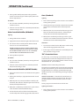
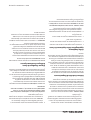
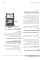
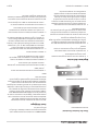
FDO Heavy Duty Oven Control
The model FDO oven thermostat is a precision-made
instrument, carefully set at the factory to accurately control
oven temperatures from 150° to 500°F, (66° to 260°C). All
adjustments are accessible from the front of the appliance
after moving the dial. To remove the dial, grasp the outer
edges and pull straight out.
By-Pass Adjustment
The Robertshaw FDO snap/throttle thermostat requires that
the by-pass ame be properly adjusted. To adjust proceed as
follows:
4
5
0
5
0
0
5
5
0
1
5
0
3
0
0
2
5
0
3
0
0
3
5
0
4
0
0
Calibration
Lock Screws
By-pass Flame
Adjuster
Indicator Mark
Calibration
Plate
Dial
Stop
MODEL
FDO
1. Ensure pilot ame is lit and adjusted.
2. Turn oven temperature control to 200°F, (93°C), and allow
the oven to heat for three minutes.
3. Turn, the oven temperature control to the lowest
position, then turn slowly counter-clockwise until the
audible “click” is heard.
4. Making sure the oven temperature control dial is not
disturbed, turn the by-pass ame adjusting screw
clockwise to decrease, or counter-clockwise to increase
the ame on the burner to the lowest possible stable
ame. When properly adjusted, the by-pass ames will
cover the entire length of the burner.
Calibration Instructions
Field calibration is seldom necessary and should not
be resorted to unless experience with cooking results
undoubtedly indicate that the control is not maintaining
the temperature for which the dial is set. To check oven
temperatures when calibrating, use only a reliable mercury
thermometer, or preferably an oven pyrometer. To check
calibration, proceed as follows:
1. Place the thermocouple of the test instrument or reliable
mercury thermometer in the center of the oven.
2. Turn the oven temperature control knob to 400°F, (204°C),
and allow the oven to cycle at least three times.
3. Continue to monitor the oven temperature, recording
the readings at 5 minute intervals until three successive
readings are within 5°F, (2°C), of each other.
If the temperature does not read within 15°F, (8°C), of the dial
setting, recalibrate as follows.
1. Remove the oven temperature control dial, making sure
the setting is not disturbed.
2. Hold the calibration plate, (located directly behind the
control dial), and loosen the two calibration lock screws
until the plate can be rotated independently of the
control.
3. Turn the calibration plate until the temperature indicated
on the plate corresponds with the reading on the test
instrument. Hold the plate in place and tighten the
screws rmly.
4. Repeat step 3 in the previous section, checking the
temperature to ensure the adjustment has been made
properly.
5. Replace the temperature control dial.
NOTE: If adjustment of the calibration plate is prevented by
the position of the lock screws, the screws can be moved to
other holes that have been tapped for them.

Part # 1382680 Rev 2 (12/09/10)Page 20
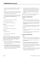
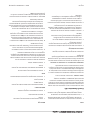
BJWA Griddle Thermostat
When the griddle surface reaches the temperature for which
the dial is set the control cuts down the ow of gas to the
amount required to keep the griddle at that temperature.
The control must be adjusted to pass enough gas to keep the
entire burner ignited. To properly adjust the by-pass setting,
proceed as follows:
1. Light the burner by turning the dial fully “ON.”
2. After 5 minutes, turn the dial clockwise to a point slightly
past, (to the right of), the rst mark on the dial.
3. Remove the dial by pulling it straight o.
4. With a screwdriver, turn the by-pass adjustment screw
counter-clockwise to decrease the ame, or clockwise to
increase the ame, until there is a minimum ame along
the entire burner.
CALIBRATION
SCREW
BY-PASS
ADJUSTMENT
SCREW
ROBERTSHAW BJWA
THERMOSTAT
Calibration
1. Use a Robertshaw test instrument with a disc-type
thermocouple, or a reliable “surface” type thermometer.
(NOTE: A drop of oil on the face of the disc will provide for
better contact.)
2. Turn ALL griddle control dials to 400°F, (240°C). allow the
temperature to stabilize by waiting for the thermostat(s)
to cycle three times before taking a temperature reading.
3. Check the temperature reading when the control cuts
down to by-pass, by placing the sensor rmly on the
griddle surface directly above the sensing bulb of the
control. Test instrument should read from 350° to 410°F,
(196° to 213°C). If the dial setting does not agree with
the test instrument reading within the above limits,
recalibrate.
NOTE: NO ATTEMPT SHOULD BE MADE TO RECALIBRATE
THE GRIDDLE CONTROL WITHIN THE WARRANTY PERIOD IF
THE TEMPERATURE IS WITHIN ±20°F OF THE DIAL SETTING.
RECALIBRATION SHOULD BE PERFORMED IF THE CONTROL IS
FOUND TO BE INACCURATE BY MORE THAN ±20°F, AND LESS
THAN ±50°F. IF THE CONTROL IS FOUND TO BE INACCURATE
BY MORE THAN ±50°F DURING THE WARRANTY PERIOD, THE
CONTROL WILL BE REPLACED UNDER WARRANTY.
To recalibrate:
1. Remove the dial and push out the center metal insert.
2. Replace the dial without the insert.
3. Holding the dial rmly in place, insert a screwdriver
through the center of the dial and seat it in the slot in
the calibration screw. DO NOT TURN THIS SCREW! Exert
pressure on the screwdriver to push the calibration stem
inward.
4. While holding the calibration stem pushed inward with
the screwdriver, turn the control DIAL to the temperature
indicated on the test instrument. Release pressure on the
calibration stem.
5. Remove the dial from the control, replace the dial insert,
and reinstall the dial on the control.
6. Set the dial to 450° F, (232° C). Check temperature
as before. If the temperature is not now within the
acceptable ±20°F, (4°C), range, the sensing element is
inoperative and the control should be replaced.
ADJUSTMENTS Continued
La page est en cours de chargement...
La page est en cours de chargement...
La page est en cours de chargement...
La page est en cours de chargement...
La page est en cours de chargement...
La page est en cours de chargement...
La page est en cours de chargement...
La page est en cours de chargement...
La page est en cours de chargement...
La page est en cours de chargement...
La page est en cours de chargement...
La page est en cours de chargement...
La page est en cours de chargement...
La page est en cours de chargement...
La page est en cours de chargement...
La page est en cours de chargement...
La page est en cours de chargement...
La page est en cours de chargement...
La page est en cours de chargement...
La page est en cours de chargement...
La page est en cours de chargement...
La page est en cours de chargement...
La page est en cours de chargement...
La page est en cours de chargement...
La page est en cours de chargement...
La page est en cours de chargement...
La page est en cours de chargement...
La page est en cours de chargement...
-
 1
1
-
 2
2
-
 3
3
-
 4
4
-
 5
5
-
 6
6
-
 7
7
-
 8
8
-
 9
9
-
 10
10
-
 11
11
-
 12
12
-
 13
13
-
 14
14
-
 15
15
-
 16
16
-
 17
17
-
 18
18
-
 19
19
-
 20
20
-
 21
21
-
 22
22
-
 23
23
-
 24
24
-
 25
25
-
 26
26
-
 27
27
-
 28
28
-
 29
29
-
 30
30
-
 31
31
-
 32
32
-
 33
33
-
 34
34
-
 35
35
-
 36
36
-
 37
37
-
 38
38
-
 39
39
-
 40
40
-
 41
41
-
 42
42
-
 43
43
-
 44
44
-
 45
45
-
 46
46
-
 47
47
-
 48
48


dans d''autres langues
- English: Garland M12 Operating instructions
Documents connexes
-
Garland E20 Series Owner Instruction Manual
-
Garland Regal Series Manuel utilisateur
-
-
-
-
-
-
-
Garland SRC Manuel utilisateur
-