
www.lg.com
OWNER’S MANUAL
PLASMA MONITOR
Please read this manual carefully before operating
your set and retain it for future reference.
P/NO: MFL62881322 (1008-REV00)
Printed in Korea
ENGLISH
La page est en cours de chargement...
La page est en cours de chargement...
La page est en cours de chargement...
La page est en cours de chargement...
La page est en cours de chargement...
La page est en cours de chargement...
La page est en cours de chargement...

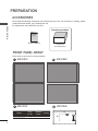
9
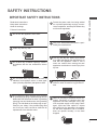
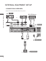
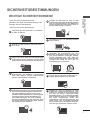
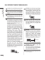
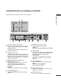
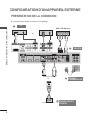
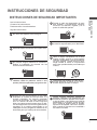
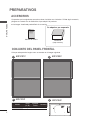
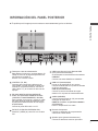
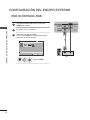
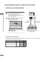
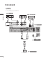
EXTERNAL EQUIPMENT SETUP
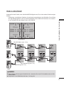
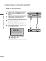
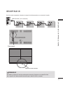
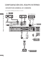
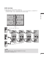
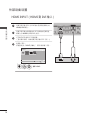
WATCHING RGB OUTPUTS
Use this function when displaying ANALOG RGB inputs of a PC to the other product.
•TousedifferentproductsconnectedtoeachotherConnectoneendofthesignalinputcable(15-
pin D-Sub Signal Cable) to the RGB OUT connector of product 1 and connect the other end to the
RGB IN connector of other products.
DVI OUT DVI IN
(SERVICE ONLY)
USB
HDMI
RGB OUT
RGB IN
SPEAKER
(8)
AC-IN
DVI OUT DVI IN
(SERVICE ONLY)
USB
HDMI
RGB OUT
RGB IN
SPEAKER
(8)
TX
RX
CONTROL
DVI OUT DVI IN
(SERVICE ONLY)
USB
HDMI
RGB OUT
RGB IN
SPEAKER
(8)
DVI OUT DVI IN
(SERVICE ONLY)
USB
HDMI
RGB OUT
RGB IN
SPEAKER
(8)
TX
RX
CONTROL
AC-IN
DVI OUT DVI IN
RGB OUT
RGB IN
DVI OUT DVI IN
RGB OUT
RGB IN
DVI OUT DVI IN
RGB OUT
RGB IN
DVI OUT DVI IN
RGB OUT
RGB IN
TX
RX
CONTROL
AC-IN
AC-IN
TX
RX
CONTROL
DVI OUT DVI IN
(SERVICE ONLY)
USB
HDMI
RGB OUT
RGB IN
SPEAKER
(8)
AC-IN
DVI OUT DVI IN
(SERVICE ONLY)
USB
HDMI
RGB OUT
RGB IN
SPEAKER
(8)
TX
RX
CONTROL
DVI OUT DVI IN
(SERVICE ONLY)
USB
HDMI
RGB OUT
RGB IN
SPEAKER
(8)
DVI OUT DVI IN
(SERVICE ONLY)
USB
HDMI
RGB OUT
RGB IN
SPEAKER
(8)
TX
RX
CONTROL
AC-IN
DVI OUT DVI IN
RGB OUT
RGB IN
DVI OUT DVI IN
RGB OUT
RGB IN
DVI OUT DVI IN
RGB OUT
RGB IN
DVI OUT DVI IN
RGB OUT
RGB IN
TX
RX
CONTROL
AC-IN
AC-IN
TX
RX
CONTROL
RS-232C
DVI
RGB
BACK PANEL
RS-232C Cable (Maximum 15 m)
DVI connection (Maximum 5 m)
RGB connection (Maximum 5 m)
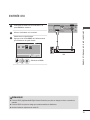
!
?
NOTE
►If you need longer connection, please use DVI boosters or DVI fiber-optic cable.
►Length of Component, HDMI is the maximum 5 m.

10
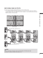
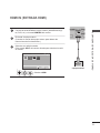
EXTERNAL EQUIPMENT SETUP
EXTERNAL EQUIPMENT SETUP
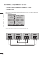
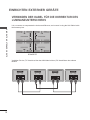
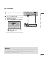
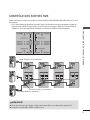
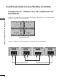
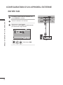
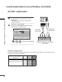
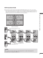
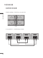
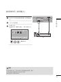
CONNECTING INTENSITY COMPENSATION
CONNECTOR
It is a connector to compensate the luminance difference, and connect it using the LAN Cable inside
the Accessory box.
DVI OUT DVI IN
(SERVICE ONLY)
USB
HDMI
RGB OUT
RGB IN
SPEAKER
(8)
AC-IN
DVI OUT DVI IN
(SERVICE ONLY)
USB
HDMI
RGB OUT
RGB IN
SPEAKER
(8)
TX
RX
CONTROL
DVI OUT DVI IN
(SERVICE ONLY)
USB
HDMI
RGB OUT
RGB IN
SPEAKER
(8)
DVI OUT DVI IN
(SERVICE ONLY)
USB
HDMI
RGB OUT
RGB IN
SPEAKER
(8)
TX
RX
CONTROL
AC-IN
DVI OUT DVI IN
RGB OUT
RGB IN
DVI OUT DVI IN
RGB OUT
RGB IN
DVI OUT DVI IN
RGB OUT
RGB IN
DVI OUT DVI IN
RGB OUT
RGB IN
TX
RX
CONTROL
AC-IN
AC-IN
TX
RX
CONTROL
BACK PANEL
Connect LAN Cable to TX, and connect to RX connector of other sets.
TX
RX
CONTROL
TX
RX
CONTROL
TX
RX
CONTROL
TX
RX
CONTROL
DVI OUT DVI IN
(SERVICE ONLY)
USB
HDMI
RGB OUT
RGB IN
SPEAKER
(8)
AC-IN
DVI OUT DVI IN
(SERVICE ONLY)
USB
HDMI
RGB OUT
RGB IN
SPEAKER
(8)
TX
RX
CONTROL
DVI OUT DVI IN
(SERVICE ONLY)
USB
HDMI
RGB OUT
RGB IN
SPEAKER
(8)
DVI OUT DVI IN
(SERVICE ONLY)
USB
HDMI
RGB OUT
RGB IN
SPEAKER
(8)
TX
RX
CONTROL
AC-IN
TX
RX
CONTROL
AC-IN
AC-IN
TX
RX
CONTROL

11
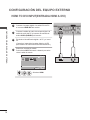
EXTERNAL EQUIPMENT SETUP
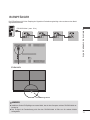
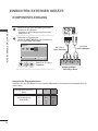
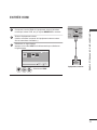
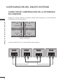
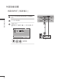
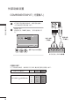
IR RECEIVER
It has the role of enabling to receive the signal of the remote control by connecting to the set.
DVI OUT DVI IN
(SERVICE ONLY)
USB
HDMI
RGB OUT
RGB IN
SPEAKER
(8)
TX
RX
CONTROL
AC-IN
Front
DVI OUT DVI IN
(SERVICE ONLY)
USB
HDMI
RGB OUT
RGB IN
SPEAKER
(8)
TX
RX
CONTROL
AC-IN
!
?
NOTE
► Install the IR receiver in the first set connected to the computer and the RS-232C cable.
► The IR signal of the remote control is sent through the RS-232C cable in cascade.
Remote Control Sensor
PC
RS-232C Cable (Maximum 15 m)

12
EXTERNAL EQUIPMENT SETUP
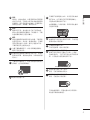
EXTERNAL EQUIPMENT SETUP
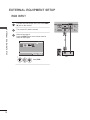
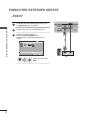
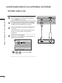
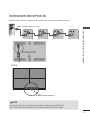
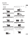
1
Connect the RGB output of the PC to the RGB
IN jack on the monitor.
2
Turn on the PC and the monitor.
3
Select an input signal.
Press the INPUT button on the remote control to
select the input signal.
RGB INPUT
1
INPUT
OK
Select RGB.
HDMI
RGB
OK
Move
Input List
Input Label
Exit
ComponentDVI-D
DVI OUT DVI IN
RGB OUT
RGB IN
SPEAKER
(8)
(SERVICE ONLY)
USB
HDMI/ DVI
PC
1

13
EXTERNAL EQUIPMENT SETUP
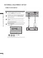
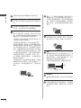
HDMI INPUT
1
Connect the HDMI output of the external equipment (digital set-
top box, DVD, etc.) to HDMI/DVI jack on the monitor.
2
Turn on the external equipment.
(Refer to the external equipment's manual for operating
instructions.)
3
Select an input signal.
Press the INPUT button on the remote control to select the input sig-
nal.
1
INPUT
OK
Select HDMI.
HDMI
RGB
OK
Move
Input List
Input Label
Exit
ComponentDVI-D
DVI OUT DVI IN
SPEAKER
(8)
RGB OUT
RGB IN
(SERVICE ONLY)
USB
HDMI/ DVI
1
external equipment
La page est en cours de chargement...

15
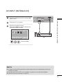
EXTERNAL EQUIPMENT SETUP
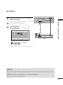
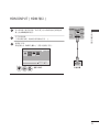
DVI INPUT
DVI OUT
SPEAKER
(8)
(SERVICE ONLY)
USB
HDMI/ DVI
DVI IN
RGB OUT
RGB IN
PC
HDMI
RGB
OK
Move
Input List
Input Label
Exit
1
INPUT
OK
Select DVI-D.
ComponentDVI-D
NOTE
► It does not support HDCP(High-bandwidth Digital Content Protection) function when it is Cascade connect-
ed.
► HDCP function may not be supported for some models of the distributor.
► This function works in the only PC mode.
1
Connect the DVI output of the PC to the DVI
IN jack on the monitor.
2
Turn on the PC and the monitor.
3
Select an input signal.
Press the INPUT button on the remote control to
select the input signal.
1

16
EXTERNAL EQUIPMENT SETUP
EXTERNAL EQUIPMENT SETUP
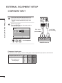
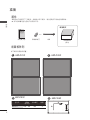
COMPONENT INPUT
BNC Cable
(not included)
Audio Cable
(not included)
DVD/STB Receiver
HDMI
RGB
OK
Move
Input List
Input Label
Exit
1
INPUT
OK
Select Component.
ComponentDVI-D
1
Connect the video/audio cable as shown in the
below figure and then, connect the power cord
•Connecttheinputterminalwithapropercolor
match.
2
Select an input signal.
Press the INPUT button on the remote control to
select the input signal.
Component Input ports
To get better picture quality, connect a DVD player to the component input ports as shown below.
Component ports on the TV Y PB PR
Video output ports
on DVD player
Y P
B PR
Y B-Y R-Y
Y Cb Cr
Y Pb Pr
La page est en cours de chargement...
La page est en cours de chargement...

19
USER MENUS
USER MENU
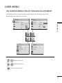
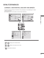
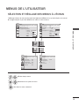
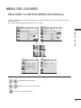
ON SCREEN MENUS SELECTION AND ADJUSTMENT
Your Monitor's OSD (On Screen Display) may differ slightly from that shown in this manual.
OPTION
PICTURE AUDIO
TIME
OK
Move
●Aspect Ratio : 16:9
● Energy Saving : Off
●Picture Mode : Standard
•Contrast 100
•Brightness 50
•Sharpness 50
•Color 60
•Tint 0
PICTURE
OK
Move
●Auto Volume : Off
●Clear Voice II : Off 3
●Balance 0
●Sound Mode : Standard
•InfiniteSound:Off
•Treble 50
•Bass 50
•Reset
AUDIO
L R
1
MENU
VOL
-
VOL
+
Display each menu.
2
OK
VOL
-
VOL
+
Select a menu item.
3
OK
Move to the pop up menu.
■Imageshown may differ from your Monitor.
OK
Move
●Clock
●Off Time : Off
●On Time : Off
●Sleep Timer : Off
●Power On Delay : Off
● Auto Off : Off
TIME
OK
Move
●Language
●ISM Method : Normal
●Factory Reset
●Set ID : 1
●Tile Mode
OPTION
R G

20
APPENDIX
APPENDIX
APPENDIX
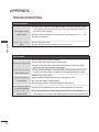
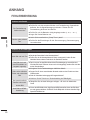
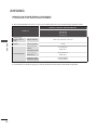
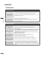
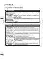
TROUBLESHOOTING
Abnormal Operation
The remote control
doesn’t work
■ Check to see if there is any object between the Monitor and the remote
control causing an obstruction. Ensure you are pointing the remote con-
trol directly at the Monitor.
■ Ensure that the batteries are installed with correct polarity (+ to +, - to -).
■ Install new batteries.
Monitor turns off sud-
denly
■ Is the sleep timer set?
■ Check the power control settings. Power interrupted.
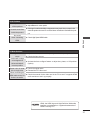
Video Problems
No picture & No sound
■ Check whether the product is turned on.
■ Is the power cord inserted into wall power outlet?
■ Test the wall power outlet, plug another product’s power cord into the outlet
where the product’s power cord was plugged in.
Picture appears slowly
after switching on
■ This is normal, the image is muted during the product startup process. Please
contact your service center, if the picture has not appeared after five minutes.
No or poor color or
poor picture
■ Adjust Color in menu option.
■ Keep a sufficient distance between the product and the VCR.
■ Are the video cables installed properly?
■ Activate any function to restore the brightness of the picture.
Horizontal/vertical bars
or picture shaking
■ Check for local interference such as an electrical appliance or power tool.
No picture when con-
necting HDMI
■ If the HDMI cables don’t support High Speed HDMI, it can cause flickers or no
screen display. In this case use the latest cables that support High Speed HDMI.
La page est en cours de chargement...
La page est en cours de chargement...

23
APPENDIX
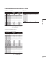
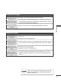
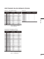
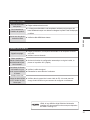
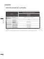
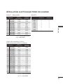
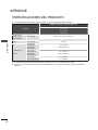
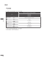
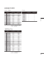
SUPPORTED DISPLAY RESOLUTION
PC Mode – Preset Mode
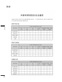
DTV Mode
Component HDMI(DTV)
480i
576i
480p
576p
720p
1080i
1080p
o
o
o
o
o
o
o
x
x
o
o
o
o
o
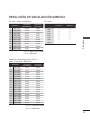
Resolution
Horizontal
Frequency
(kHz)
Vertical
Frequency (Hz)
1 640 x 350 31.468 70.09
2 720 x 400 31.469 70.08
3 640 x 480 31.469 59.94
4 800 x 600 37.879 60.31
5 1024 x 768 48.363 60.00
6 1280 x 768 47.776 59.870
7 1360 x 768 47.712 60.015
8 1280 x 1024 63.981 60.020
9 1600 x 1200 75.00 60.00
10 1920 x 1080 67.50 60.00
•
1 to 10 : HDMI / DVI-D Mode
•
1 to 9 : RGB Mode
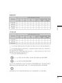
Component Video Input (Y, P
B, Pr)
Component & HDMI(DTV) Mode
Resolution
Horizontal
Frequency
(kHz)
Vertical
Frequency (Hz)
1 720 x 480 15.75 60.00
2 720 x 480 15.73 59.94
3 720 x 576 15.625 50.00
4 720 x 480 31.47 59.94
5 720 x 480 31.50 60.00
6 720 x 576 31.25 50.00
7 1280 x 720 44.96 59.94
8 1280 x 720 45.00 60.00
9 1280 x 720 37.50 50.00
10 1920 x 1080 33.72 59.94
11 1920 x 1080 33.75 60.00
12 1920 x 1080 28.125 50.00
13 1920 x 1080 67.432 59.94
14 1920 x 1080 67.50 60.00
15 1920 x 1080 56.250 50.00
16 1920 x 1080 27.00 24.00
17 1920 x 1080 33.75 30.00
•
1 to 15 : Component mode
•
4 to 17 : HDMI mode

Record the model number and serial number of the
monitor.
Refer to the label on the back cover and quote this
information to your dealer when requiring any service.
MODEL
SERIAL
La page est en cours de chargement...
La page est en cours de chargement...
La page est en cours de chargement...
La page est en cours de chargement...
La page est en cours de chargement...
La page est en cours de chargement...
La page est en cours de chargement...
La page est en cours de chargement...

9
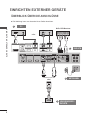
EINRICHTEN EXTERNER GERÄTE
RGB-AUSGÄNGE
Verwenden Sie diese Funktion, wenn Sie ANALOGE RGB-Signale eines PCs auf dem anderen Produkt anzeigen
möchten.
•VerwendungverschiedenerProdukte,dieaneinanderangeschlossensindSchließenSieeinEnde
des Signaleingangskabels (15-Pin-D-Sub-Signalkabel) an den RGB OUT.Anschluss von Produkt 1
an und schließen Sie das andere Ende an den RGB IN.
DVI OUT DVI IN
(SERVICE ONLY)
USB
HDMI
RGB OUT
RGB IN
SPEAKER
(8)
TX
RX
CONTROL
AC-IN
DVI OUT DVI IN
(SERVICE ONLY)
USB
HDMI
RGB OUT
RGB IN
SPEAKER
(8)
TX
RX
CONTROL
DVI OUT DVI IN
(SERVICE ONLY)
USB
HDMI
RGB OUT
RGB IN
SPEAKER
(8)
DVI OUT DVI IN
(SERVICE ONLY)
USB
HDMI
RGB OUT
RGB IN
SPEAKER
(8)
TX
RX
CONTROL
AC-IN
DVI OUT DVI IN
RGB OUT
RGB IN
DVI OUT DVI IN
RGB OUT
RGB IN
DVI OUT DVI IN
RGB OUT
RGB IN
DVI OUT DVI IN
RGB OUT
RGB IN
TX
RX
CONTROL
AC-IN
AC-IN
RS-232C
DVI
RGB
RÜCKSEITE
RS-232C-Kabel (max. 15 m)
DVI-Verbindung (max. 5 m)
RGB-Verbindung (max. 5 m)
!
?
HINWEIS
►Wenn längere Verbindungen erforderlich sind, verwenden Sie einen DVI-Verstärker oder ein DVI-
Glasfaserkabel.
►Komponente- und HDMI-Kabel darf max. 5 m lang sein.
DVI OUT DVI IN
(SERVICE ONLY)
USB
HDMI
RGB OUT
RGB IN
SPEAKER
(8)
AC-IN
DVI OUT DVI IN
(SERVICE ONLY)
USB
HDMI
RGB OUT
RGB IN
SPEAKER
(8)
TX
RX
CONTROL
DVI OUT DVI IN
(SERVICE ONLY)
USB
HDMI
RGB OUT
RGB IN
SPEAKER
(8)
DVI OUT DVI IN
(SERVICE ONLY)
USB
HDMI
RGB OUT
RGB IN
SPEAKER
(8)
TX
RX
CONTROL
AC-IN
DVI OUT DVI IN
RGB OUT
RGB IN
DVI OUT DVI IN
RGB OUT
RGB IN
DVI OUT DVI IN
RGB OUT
RGB IN
DVI OUT DVI IN
RGB OUT
RGB IN
TX
RX
CONTROL
AC-IN
AC-IN
TX
RX
CONTROL

10
EINRICHTEN EXTERNER GERÄTE
EINRICHTEN EXTERNER GERÄTE
VERBINDEN DER KABEL FÜR DIE KORREKTUR DES
LUMINANZUNTERSCHIEDS
It is a connector to compensate the luminance difference, and connect it using the LAN Cable inside
the Accessory box.
DVI OUT DVI IN
(SERVICE ONLY)
USB
HDMI
RGB OUT
RGB IN
SPEAKER
(8)
AC-IN
DVI OUT DVI IN
(SERVICE ONLY)
USB
HDMI
RGB OUT
RGB IN
SPEAKER
(8)
TX
RX
CONTROL
DVI OUT DVI IN
(SERVICE ONLY)
USB
HDMI
RGB OUT
RGB IN
SPEAKER
(8)
DVI OUT DVI IN
(SERVICE ONLY)
USB
HDMI
RGB OUT
RGB IN
SPEAKER
(8)
TX
RX
CONTROL
AC-IN
DVI OUT DVI IN
RGB OUT
RGB IN
DVI OUT DVI IN
RGB OUT
RGB IN
DVI OUT DVI IN
RGB OUT
RGB IN
DVI OUT DVI IN
RGB OUT
RGB IN
TX
RX
CONTROL
AC-IN
AC-IN
TX
RX
CONTROL
RÜCKSEITE
Verbinden Sie den „TX“-Anschluss über das LAN-Kabel mit den „RX“-Anschlüssen der anderen
Module.
TX
RX
CONTROL
TX
RX
CONTROL
TX
RX
CONTROL
TX
RX
CONTROL
DVI OUT DVI IN
(SERVICE ONLY)
USB
HDMI
RGB OUT
RGB IN
SPEAKER
(8)
AC-IN
DVI OUT DVI IN
(SERVICE ONLY)
USB
HDMI
RGB OUT
RGB IN
SPEAKER
(8)
TX
RX
CONTROL
DVI OUT DVI IN
(SERVICE ONLY)
USB
HDMI
RGB OUT
RGB IN
SPEAKER
(8)
DVI OUT DVI IN
(SERVICE ONLY)
USB
HDMI
RGB OUT
RGB IN
SPEAKER
(8)
TX
RX
CONTROL
AC-IN
TX
RX
CONTROL
AC-IN
AC-IN
TX
RX
CONTROL

11
EINRICHTEN EXTERNER GERÄTE
IR-EMPFÄNGER
Der IR-Empfänger wird für den Empfang des Signals der Fernbedienung benötigt und muss dazu an das Modul
angeschlossen werden.
Vorderseite
DVI OUT DVI IN
(SERVICE ONLY)
USB
HDMI
RGB OUT
RGB IN
SPEAKER
(8)
TX
RX
CONTROL
AC-IN
!
?
HINWEIS
► Installieren Sie den IR-Empfänger am ersten Modul, das mit dem Computer und dem RS-232C-Kabel ver-
bunden ist.
► Das IR-Signal der Fernbedienung wird über das RS-232C-Kabel in Reihe an die anderen Module
weitergeleitet.
Fernbedienungssensor
PC
RS-232C-Kabel (max. 15 m)
DVI OUT DVI IN
(SERVICE ONLY)
USB
HDMI
RGB OUT
RGB IN
SPEAKER
(8)
TX
RX
CONTROL
AC-IN
La page est en cours de chargement...
La page est en cours de chargement...
La page est en cours de chargement...

15
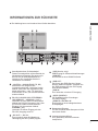
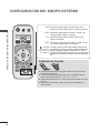
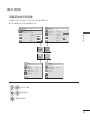
EINRICHTEN EXTERNER GERÄTE
1
Schließen Sie den DVI-Ausgang des PC an
die DVI IN-Buchse des Monitors an.
2
Turn on the PC and the monitor.
3
Wählen Sie ein Eingangssignal.
Drücken Sie INPUT (Quelle) auf der Fernbedienung,
um ein Eingangssignal auszuwählen.
DVI-EINGANG
DVI OUT
SPEAKER
(8)
(SERVICE ONLY)
USB
HDMI/ DVI
DVI IN
RGB OUT
RGB IN
PC
HDMI
RGB
OK
Bew.
Eingangsliste
Eingangsbezeichnung
Ausgang
1
INPUT
OK
Wählen sie die option
DVI-D.
KomponenteDVI-D
HINWEIS
► Bei Schaltung in Reihe wird die HDCP (High-Bandwidth Digital Content Protection) Funktion nicht unterstüt-
zt.
► Bei einigen Modellen des Distributors wird die HDCP-Funktion möglicherweise nicht unterstützt.
► Diese Funktion ist nur im PC-Modus verfügbar.
1
La page est en cours de chargement...

17
EINRICHTEN EXTERNER GERÄTE
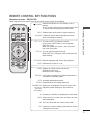
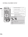
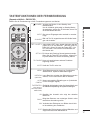
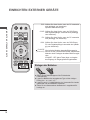
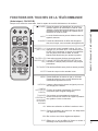
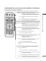
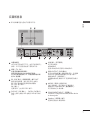
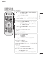
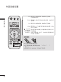
TASTENFUNKTIONEN DER FERNBEDIENUNG
(Separat erhältlich : PAC60C1B)
Richten Sie die Fernbedienung auf den Fernbedienungssensor am Monitor.
INPUT
AV MODE
BACK
OK
ISM
EXIT
RGB
COMP DVI
HDMI
ON OFF
ID MODE
VOL
-
VOL
+
MENU
NATURAL
AUTO
CONFIG
SET 1
SET 3
SET 2
SET 4
SET ALL
TILE MODE
MUTE
(POWER)
INPUT
AV MODE
Versetzt den Monitor in den Standby- bzw.
Betriebsmodus.
Um die 4 Module gleichzeitig im Standby-Modus
einzuschalten, warten Sie 10 Sekunden, bevor Sie
die Einschalttaste drücken.
Der externe Eingangsmodus wechselt in normaler
Folge.
Bild und Ton für angeschlossene AV-Geräte festle-
gen und einstellen.
SET 1 bis SET 4
SET ALL
TILE MODE
MUTE
Jedes Modul (SET) kann einzeln betrieben werden.
(Wenn Sie z. B. die Taste SET 1 drücken, läuft nur
60PJ101C.) Wenn Sie eine der Tasten SET 1 bis
SET 4 drücken, wirkt sich die Einschalttaste auf
alle Module aus.
Es können alle Panels auf einmal gesteuert werden.
Wenn Sie die Taste SET ALL drücken, können Sie
für jedes Modul eine andere Einstellung wählen.
Muss mit verschiedenen anderen Produkten
angezeigt werden.
Stellt den Ton Ein oder Aus.
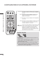
MENU
NATURAL
(Natürlich)
AUTO
CONFIG
TASTENFELD
(Nach oben(Vol +)/
Nach unten(Vol–)/Nach
links/Nach rechts)
OK
BACK
ISM
EXIT
Zeigt Bildschirmmenüs einzeln an. Schließt das
aktuelle Menü. Speichert Menüänderungen.
Leere Bereiche zwischen den Bildschirmen werden
entfernt, um ein natürlicheres Bild zu erhalten.
Nimmt automatische Einstellungen vor (funktioniert
nur bei analogem Signal).
Ermöglicht die Navigation in den On-Screen-Menüs und
die individuelle Anpassung der Systemeinstellungen.
Bestätigt Ihre Auswahl oder zeigt den aktuellen
Modus an.
Bringt den Benutzer zum vorherigen Schritt in einer
interaktiven Anwendung zurück.
Verhindert das Einbrennen von Bildern durch leich-
te Verschiebung des Farbblocks.
Beendet alle Einblendungen auf dem Bildschirm und
zeigt wieder das volle Monitorbild an.
La page est en cours de chargement...
La page est en cours de chargement...

20
ANHANG
ANHANG
ANHANG
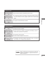
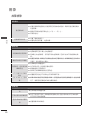
FEHLERBEHEBUNG
Probleme beim Betrieb
Die Fernbedienung
funktioniert nicht.
■ Prüfen Sie, ob sich zwischen Monitor und Fernbedienung Gegenstände
befinden, die die Signalübertragung behindern. Richten Sie die
Fernbedienung direkt auf den Monitor.
■ Prüfen Sie, ob die Batterien richtig eingelegt wurden (+ zu +, – zu –).
■ Legen Sie frische Batterien ein.
Monitor geht plötzlich
aus
■ Ist die Schlummerfunktion („Sleep Timer“) aktiv?
■ Prüfen Sie die Einstellungen für die Stromversorgung. Stromversorgung
ist unterbrochen.
Probleme bei der Bildausgabe
Kein Bild und kein Ton
■ Prüfen Sie, ob das Produkt eingeschaltet ist.
■ Steckt das Stromkabel in der Netzsteckdose?
■ Prüfen Sie, ob die Netzsteckdose mit Strom versorgt wird, indem Sie das
Netzkabel eines anderen Produkts in die Steckdose stecken.
Das Bild wird nach
dem Einschalten nur
langsam angezeigt
■ Das ist normal, da das Bild während des Einschaltvorgangs unterdrückt wird.
Wird das Bild nach 5 Minuten immer noch nicht angezeigt, wenden Sie sich bitte
an den Kundendienst.
Keine oder schlechte
Farbe oder schlechtes
Bild
■ Korrigieren Sie die Farbeinstellungen mithilfe des Menüs.
■ Sorgen Sie für einen ausreichenden Abstand zwischen dem Produkt und dem
Videorecorder.
■ Sind die Videokabel ordnungsgemäß angeschlossen?
■ Aktivieren Sie die Funktion zur Wiederherstellung der Bildhelligkeit.
Horizontale/vertikale
Streifen oder wack-
elndes Bild
■ Überprüfen Sie, ob lokale Störungen vorliegen, z. B. durch ein elektrisches
Gerät.
Kein Bild bei HDMI-
Verbindung
■ Wenn das HDMI-Kabel kein High-Speed-HDMI unterstützt, kann das Bild flack-
ern oder ganz ausbleiben. Schließen Sie die Bildquelle mit einem aktuellen High-
Speed-HDMI-Kabel an.
La page est en cours de chargement...
La page est en cours de chargement...
La page est en cours de chargement...

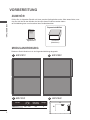
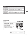
Bitte lesen Sie vor der Bedienung des Gerätes die
Vorsichtshinweise.
Modell- und Seriennummer befinden sich auf der
Rückseite sowie an der Seite des Gerätes. Bitte notieren
Sie diese Nummern zum späteren Gebrauch.
MODELL
SERIENNUMMER
La page est en cours de chargement...

2
AVERTISSEMENT/
ATTENTION
AVERTISSEMENT/ATTENTION
ATTENTION
cet appareil est un produit de catégorie A.
Dans un environnement domestique, cet appar-
eil peut provoquer des interférences radio ; si tel
est le cas, vous devez prendre les mesures
appropriées.
Le symbole de l'éclair en forme de
flèche dans un triangle équilatéral
signale à l'utilisateur la présence
dans la coque de l'appareil d'une
tension dangereuse et non isolée pouvant
être d'amplitude suffisante pour constituer un
risque d'électrocution.
Le symbole du point d'exclamation
dans un triangle équilatéral signale à
l'utilisateur la présence d'importantes instructions
d'utilisation et d'entretien dans la documentation
accompagnant l'appareil.
AFIN DE RÉDUIRE LE RISQUE
D'ÉLECTROCUTION, NE RETIREZ PAS
LE CAPOT ARRIÈRE. AUCUNE PIÈCE
N'EST RÉPARABLE PAR L'UTILISATEUR
LUI-MÊME. CONFIEZ L'ENTRETIEN DE
CET APPAREIL À DU PERSONNEL
QUALIFIÉ.
AVERTISSEMENT/ATTENTION
AFIN DE RÉDUIRE LE RISQUE D'INCENDIE
ET D'ÉLECTROCUTION, N'EXPOSEZ PAS
L'APPAREIL À LA PLUIE OU À L'HUMIDITÉ.
ATTENTION
Ne tentez pas de modifier ce produit de quelque
manière que ce soit sans autorisation écrite de LG
Electronics. Toute modification non autorisée pour-
ra annuler le droit d'utilisation du produit.
La page est en cours de chargement...
La page est en cours de chargement...
La page est en cours de chargement...
La page est en cours de chargement...
La page est en cours de chargement...
La page est en cours de chargement...
La page est en cours de chargement...
La page est en cours de chargement...
La page est en cours de chargement...
La page est en cours de chargement...
La page est en cours de chargement...
La page est en cours de chargement...
La page est en cours de chargement...
La page est en cours de chargement...
La page est en cours de chargement...
La page est en cours de chargement...
La page est en cours de chargement...
La page est en cours de chargement...
La page est en cours de chargement...
La page est en cours de chargement...
La page est en cours de chargement...
La page est en cours de chargement...
La page est en cours de chargement...
La page est en cours de chargement...
La page est en cours de chargement...
La page est en cours de chargement...
La page est en cours de chargement...
La page est en cours de chargement...
La page est en cours de chargement...
La page est en cours de chargement...
La page est en cours de chargement...
La page est en cours de chargement...
La page est en cours de chargement...
La page est en cours de chargement...
La page est en cours de chargement...
La page est en cours de chargement...
La page est en cours de chargement...
La page est en cours de chargement...
La page est en cours de chargement...
La page est en cours de chargement...
La page est en cours de chargement...
La page est en cours de chargement...
La page est en cours de chargement...
La page est en cours de chargement...
La page est en cours de chargement...
La page est en cours de chargement...
La page est en cours de chargement...
La page est en cours de chargement...
La page est en cours de chargement...
La page est en cours de chargement...
La page est en cours de chargement...
La page est en cours de chargement...
La page est en cours de chargement...
La page est en cours de chargement...
La page est en cours de chargement...
La page est en cours de chargement...
La page est en cours de chargement...
La page est en cours de chargement...
La page est en cours de chargement...
La page est en cours de chargement...
La page est en cours de chargement...
La page est en cours de chargement...
La page est en cours de chargement...
La page est en cours de chargement...
La page est en cours de chargement...
La page est en cours de chargement...
La page est en cours de chargement...
La page est en cours de chargement...
La page est en cours de chargement...
La page est en cours de chargement...
La page est en cours de chargement...
La page est en cours de chargement...
La page est en cours de chargement...
La page est en cours de chargement...
-
 1
1
-
 2
2
-
 3
3
-
 4
4
-
 5
5
-
 6
6
-
 7
7
-
 8
8
-
 9
9
-
 10
10
-
 11
11
-
 12
12
-
 13
13
-
 14
14
-
 15
15
-
 16
16
-
 17
17
-
 18
18
-
 19
19
-
 20
20
-
 21
21
-
 22
22
-
 23
23
-
 24
24
-
 25
25
-
 26
26
-
 27
27
-
 28
28
-
 29
29
-
 30
30
-
 31
31
-
 32
32
-
 33
33
-
 34
34
-
 35
35
-
 36
36
-
 37
37
-
 38
38
-
 39
39
-
 40
40
-
 41
41
-
 42
42
-
 43
43
-
 44
44
-
 45
45
-
 46
46
-
 47
47
-
 48
48
-
 49
49
-
 50
50
-
 51
51
-
 52
52
-
 53
53
-
 54
54
-
 55
55
-
 56
56
-
 57
57
-
 58
58
-
 59
59
-
 60
60
-
 61
61
-
 62
62
-
 63
63
-
 64
64
-
 65
65
-
 66
66
-
 67
67
-
 68
68
-
 69
69
-
 70
70
-
 71
71
-
 72
72
-
 73
73
-
 74
74
-
 75
75
-
 76
76
-
 77
77
-
 78
78
-
 79
79
-
 80
80
-
 81
81
-
 82
82
-
 83
83
-
 84
84
-
 85
85
-
 86
86
-
 87
87
-
 88
88
-
 89
89
-
 90
90
-
 91
91
-
 92
92
-
 93
93
-
 94
94
-
 95
95
-
 96
96
-
 97
97
-
 98
98
-
 99
99
-
 100
100
-
 101
101
-
 102
102
-
 103
103
-
 104
104
-
 105
105
-
 106
106
-
 107
107
-
 108
108
-
 109
109
-
 110
110
-
 111
111
-
 112
112
-
 113
113
-
 114
114
-
 115
115
-
 116
116
-
 117
117
-
 118
118
-
 119
119
-
 120
120
-
 121
121
-
 122
122
-
 123
123
-
 124
124


LG 60PJ101C Le manuel du propriétaire
- Catégorie
- Téléviseurs
- Taper
- Le manuel du propriétaire
dans d''autres langues
- English: LG 60PJ101C Owner's manual
- español: LG 60PJ101C El manual del propietario
- Deutsch: LG 60PJ101C Bedienungsanleitung